Developing Firmware for Infineon XMC Devices with Visual Studio
This tutorial shows how to develop firmware for the Infineon XMC devices with Visual Studio and VisualGDB. Before you begin, install VisualGDB.
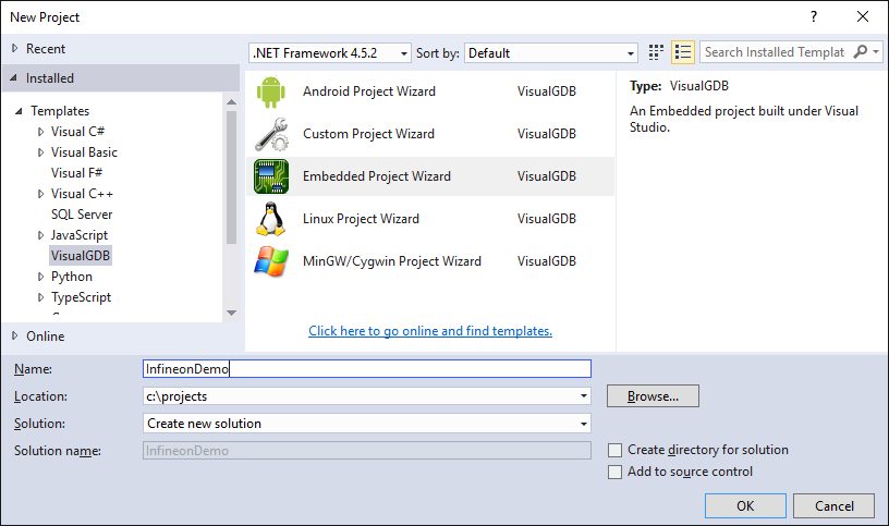
- Start Visual Studio and open the VisualGDB Embedded Project Wizard:
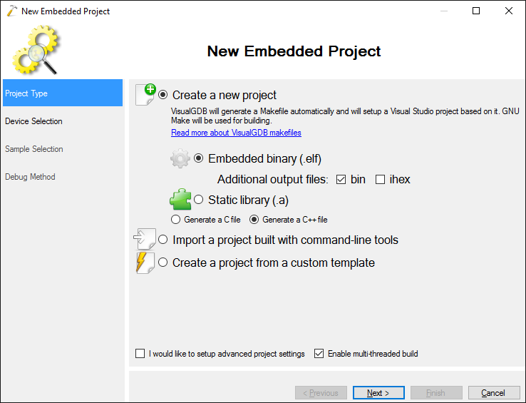
- On the first page select “Create a new project -> Embedded Binary”:
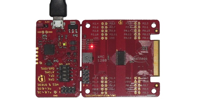
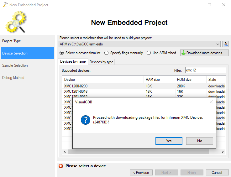
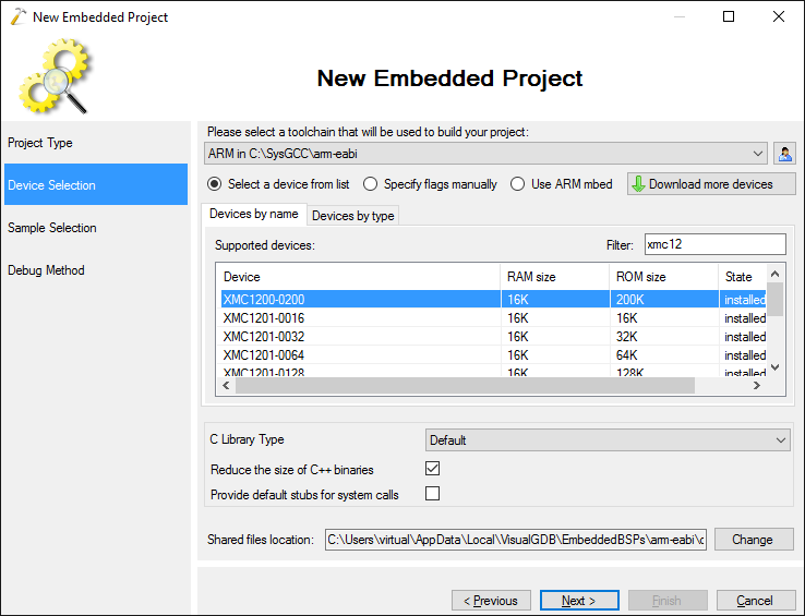
- On the Device Selection page select the ARM toolchain (if it’s not installed, VisualGDB will install it automatically). Then choose your Infineon device from the list. In this example we will use the XMC1200 Boot Kit, so we select the XMC1200-0200 device. if this is the first time you are creating a project for Infineon devices, VisualGDB will automatically download and install the necessary library files:
- Once the files are downloaded and the device is shown in the list, press “Next” to go to the sample selection page:
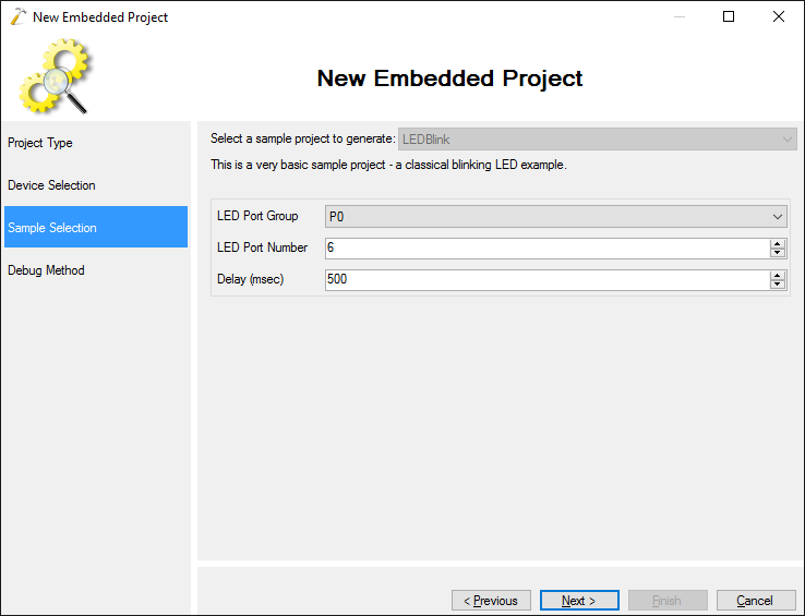
- On the Sample Selection page select the port and pin where your LED is connected. On the XMC1200 Boot Kit there are 5 LEDs connected to ports P0_0, P0_2, P0_5, P0_6 and P0_7. We will usethe P0_6 port in this example:
- The Infineon development boards come with on-board Segger J-Link, so we will select “Segger J-Link” as the debug method. VisualGDB will automatically configure the J-Link software based on your device type:
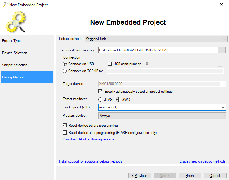 If you don’t have the J-Link software installed, you can download it from the Segger website.
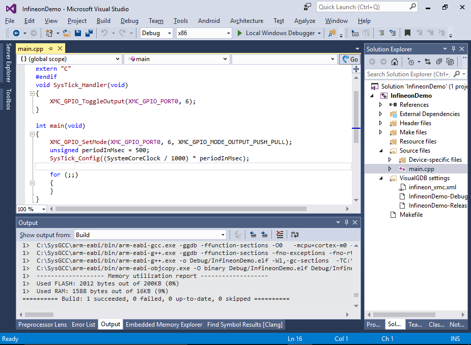
 - Press “Finish” to generate your project. Once it is generated, you can build it via Build->Build Solution. Note how VisualGDB displays the memory utilization at the end of the build log:
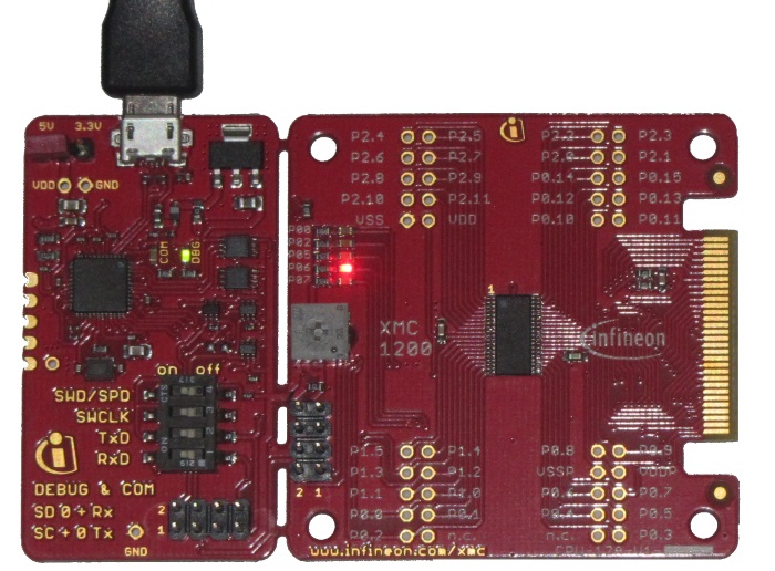
- Press F5 to start debugging note how the red LED on the board marked with P06 will start blinking:
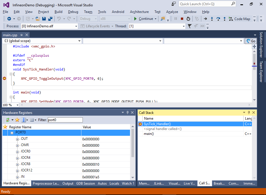
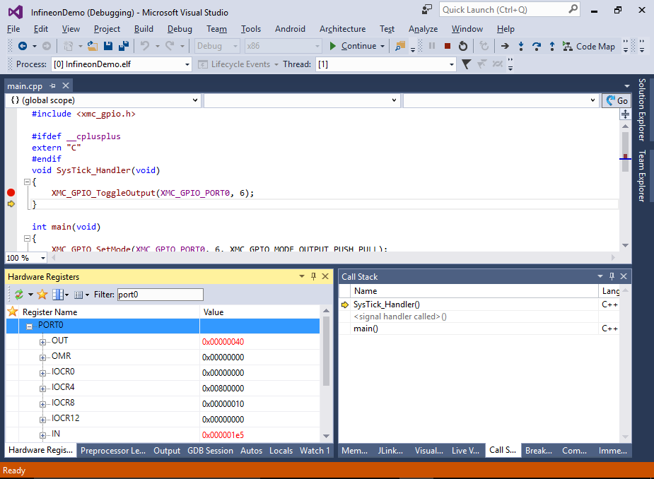
- Set a breakpoint in the SysTick_Handler() function in the main file. Once it triggers, you can use the Hardware Registers window to quickly find the registers like PORT0_OUT and examine the state of the hardware:
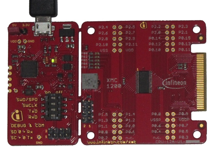
- Step over the XMC_GPIO_ToggleOutput() function. Note how the LED state changes:
- The value of the OUT register will change accordingly:
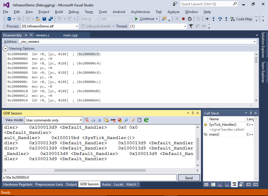
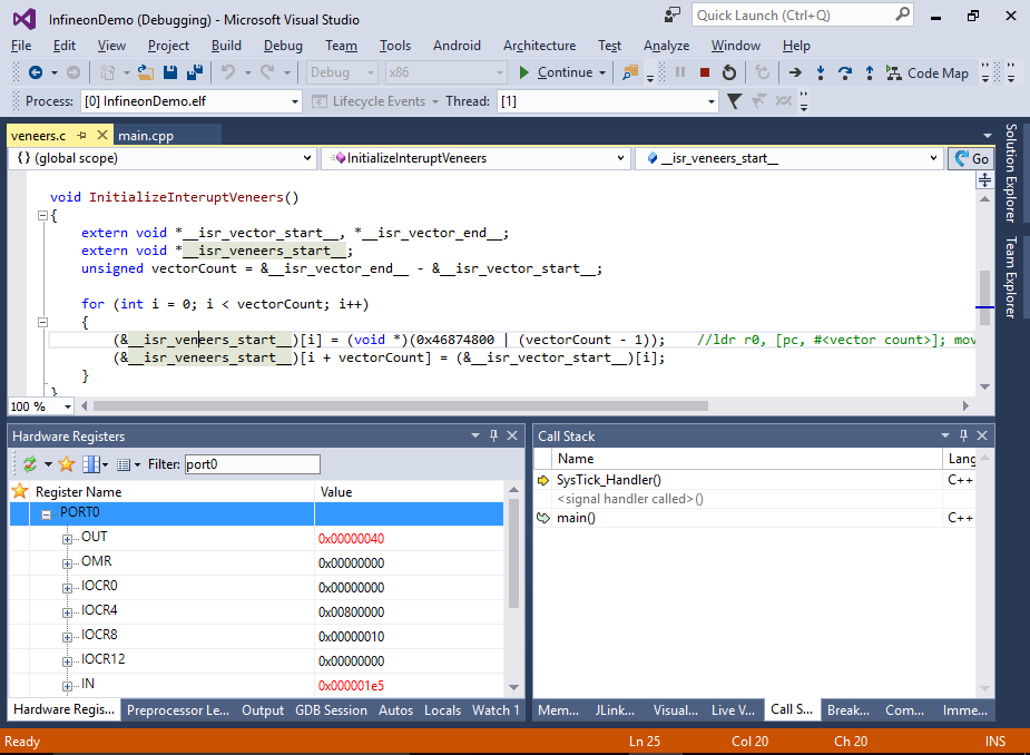
- Once important concept worth mentioning is the way XMC1xxx devices handle interrupts. The Cortex-M0 core expects the interrupt vector table to be located at address 0x00000000, however the XMC1xxx devices don’t have neither RAM nor FLASH mapped there. Instead, the 0x00000000 address contains a constant handler table that expects the first handler to be at address 0x20000000 (start of RAM), the next one at 0x20000004 and so on. The startup code from Infineon examples includes special code fragments called interrupt veneers that are placed at the beginning of RAM and jump to the actual interrupt handlers. VisualGDB startup code uses a similar technique: at startup time it copies the interrupt vector table from FLASH into RAM and generates interrupt veneers that jump to the handlers referenced in the copied table:
- You can explore the veneers by opening the Disassembly view and going to address 0x20000000. You will see that each veneer loads the target address from a subsequent entry in the table. The table contents can be conveniently viewed as a set of addresses via the GDB’s “x” command:
x/30a <start address>
The command will display the next 30 entries at given address and annotate them with the symbol names. Note that most interrupt handlers default to the Default_handler as they are not defined anywhere in the code: