Creating USB devices with mbed and VisualGDB
This tutorial shows how to use the mbed framework to create firmware for USB devices. We will create a basic USB communications device and show how to debug its firmware.
Before you begin, install VisualGDB 5.1 or later and update your embedded tools via Tools->Embedded Tools Manager:
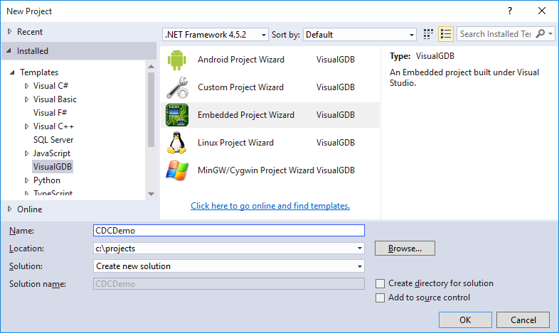
- Open Visual Studio and launch the VisualGDB Embedded Project wizard:
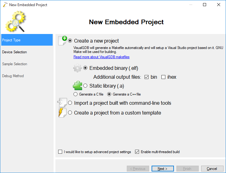
- Proceed with the default settings on the first page:
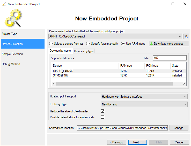
- On the next page select the device you are targeting. In this tutorial we will target the STM32F4Discovery board (DISCO_F407VG), however every device supported by mbed should work the same. Ensure you select “Newlib-nano” as your C library:
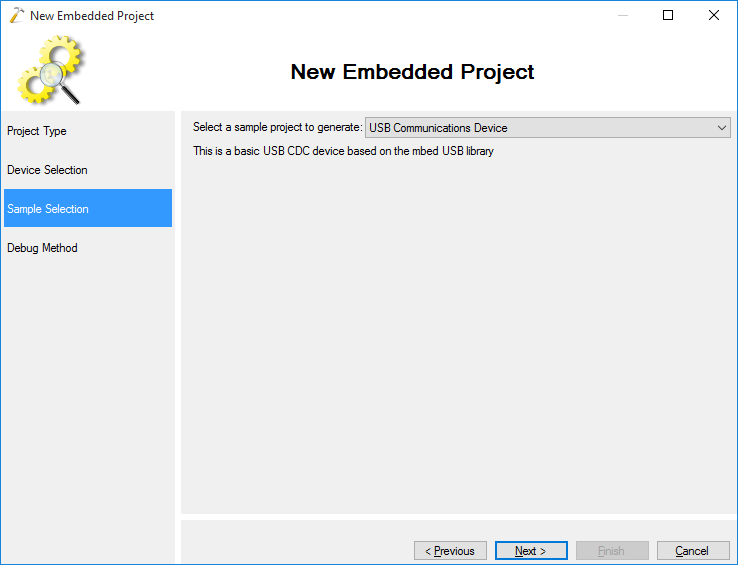
- On the next page select the “USB Communications device” sample:
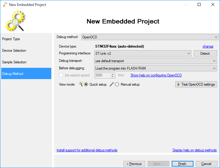
- On the last page of the wizard select the OpenOCD debug method unless you are using Segger J-Link that comes with its own software (select Segger J-Link instead of OpenOCD to use it):
- Press Finish to generate the project. If you try to build it now, VisualGDB will display an error instructing you to fix the USBDevice.cpp file. USBDevice.cpp is a part of the mbed framework and it uses the #ifdef DEBUG directive to enable verbose logging of USB events. This considerably slows down everything and can make your device unrecognizable by the PC.
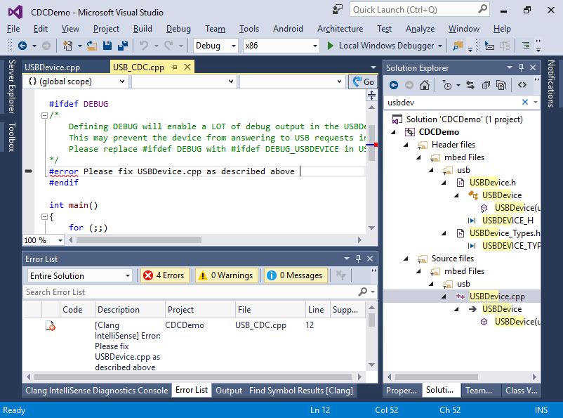
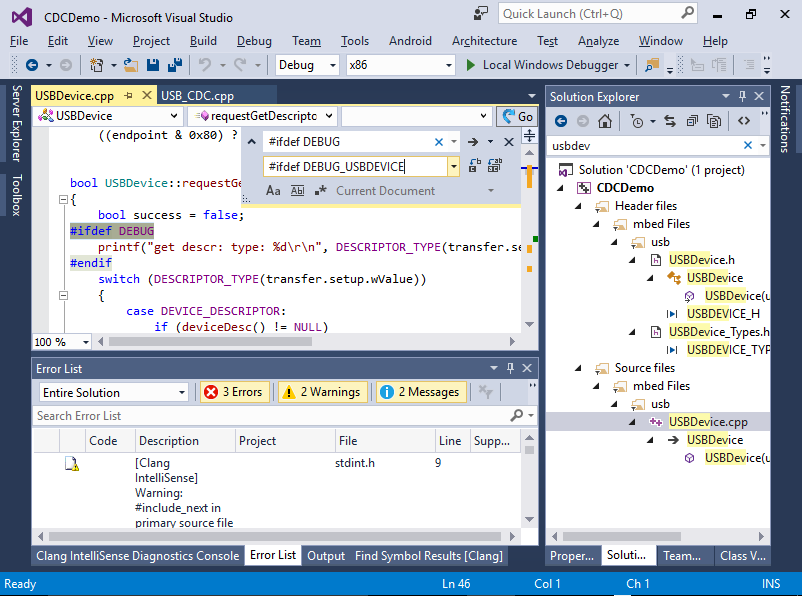
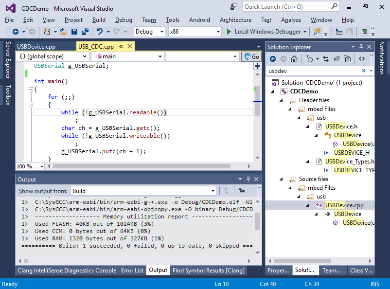
- To fix this, simply open the USBDevice.cpp file and replace #ifdef DEBUG with #ifdef DEBUG_USBDEVICE so the DEBUG macro won’t enable USB-specific tracing anymore. Then delete the #error directive in your main source file:
- Now the project should build without errors:
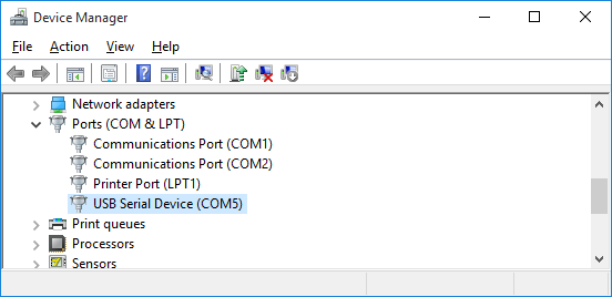
- Press F5 to begin debugging. Connect the second USB connector on your board (not the one used for JTAG debugging) and check the Device Manager for a new USB Serial Device:
 If you are not using Windows 10 or later, you may need to install the mbed USB CDC driver.
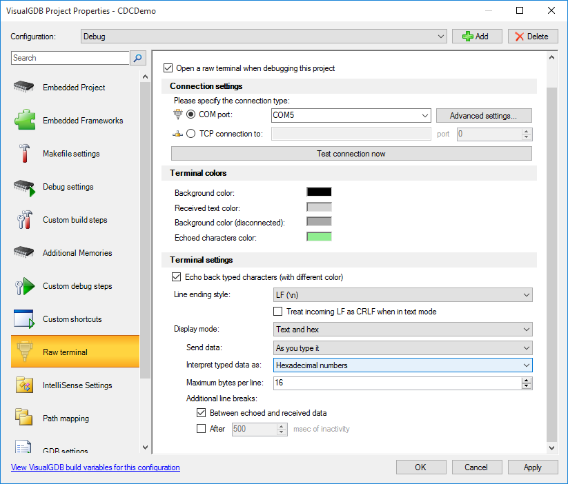
 - If you are using VisualGDB Custom edition or higher, open VisualGDB project properties and enable raw terminal on the virtual COM port in hexadecimal mode. Otherwise use any third-party terminal program of your choice to connect to it:
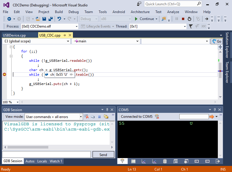
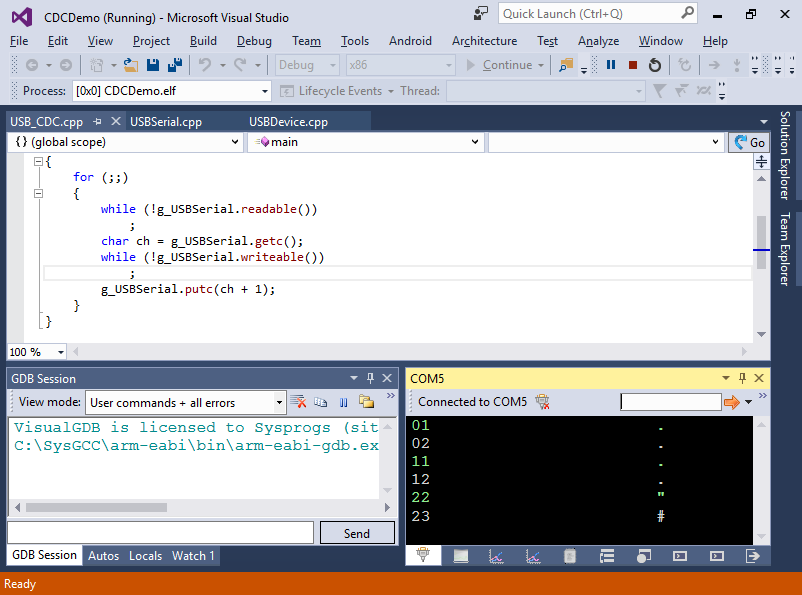
- Restart debugging and set a breakpoint after the call to g_USBSerial.getc(). Type some character code in the terminal (e.g. ’55’) and observe how your program receives it:
- However if you resume your program, you won’t see the character sent back by the firmware. If you step into the character sending code, you will see that the USBSerial::_putc() method returns prematurely because the terminal_connected variable is not set. Set it to true in the debugger and continue:
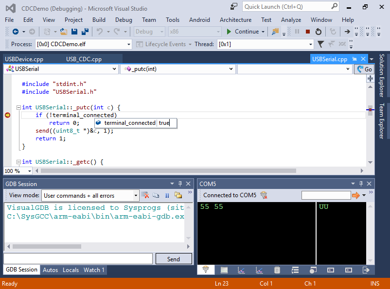
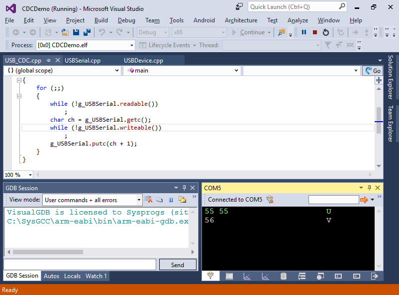
- Observe how the character code got increased by one and echoed back:
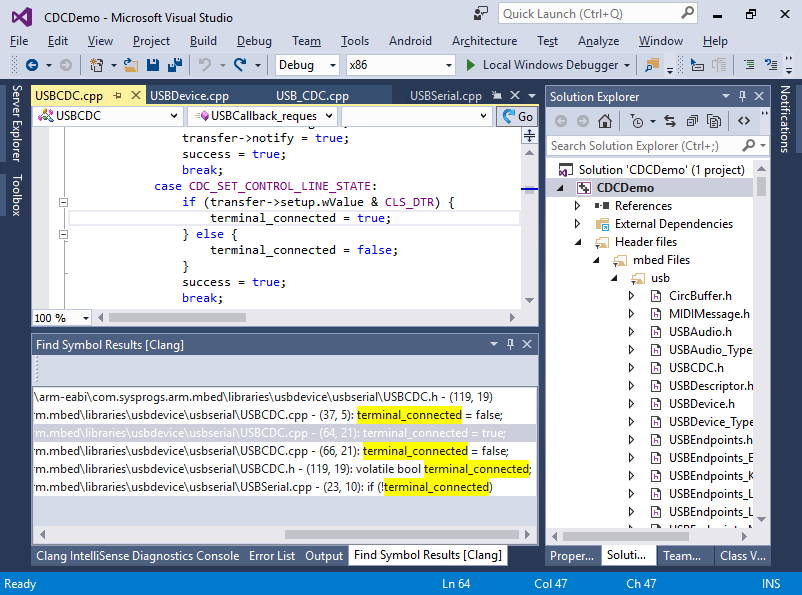
- Click on the terminal_connected field and press Shift-F12 to highlight all references. You will see that it is only set to true when the terminal program sets the virtual DTR signal. As we did not configure the terminal to use use hardware handshake, the signal was not modified and terminal_connected was false:
- Comment out the terminal_connected check and hit F5 to build your program and launch it again:
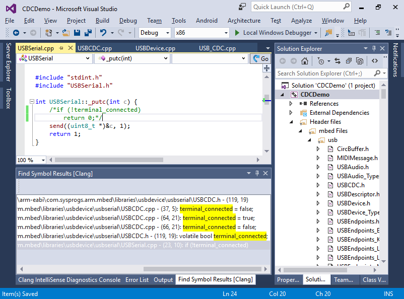
- Recheck that the characters are echoed back correctly:
- Note that the USBSerial.cpp file modified in the previous step is located in the shared directory and will be reused in all your mbed-based projects. If you want your project to use a separate copy of the mbed framework that won’t affect any other project, you can covert your project to a stand-alone one via VisualGDB Project Properties:
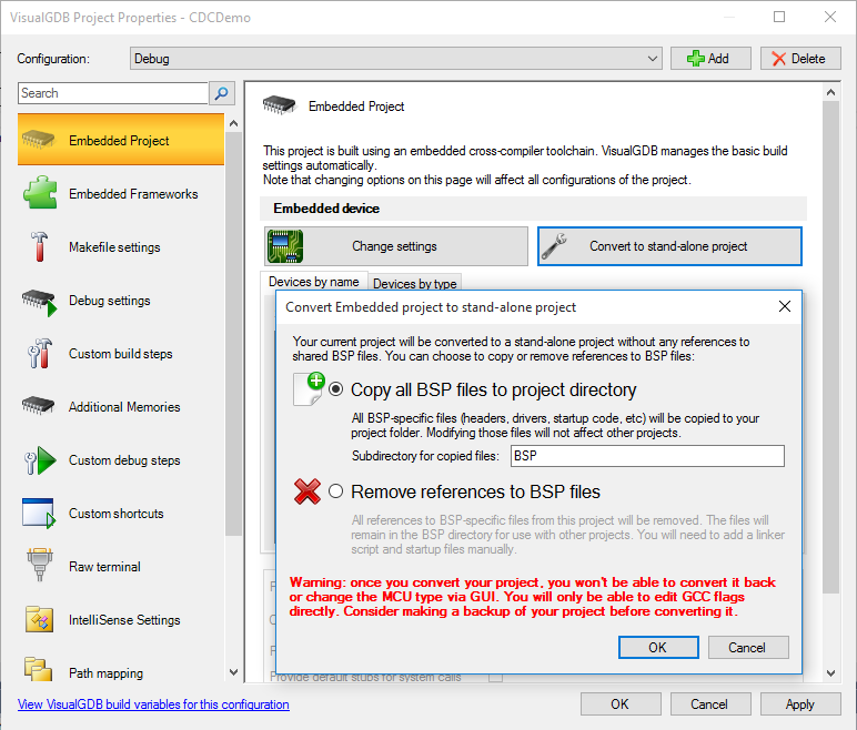
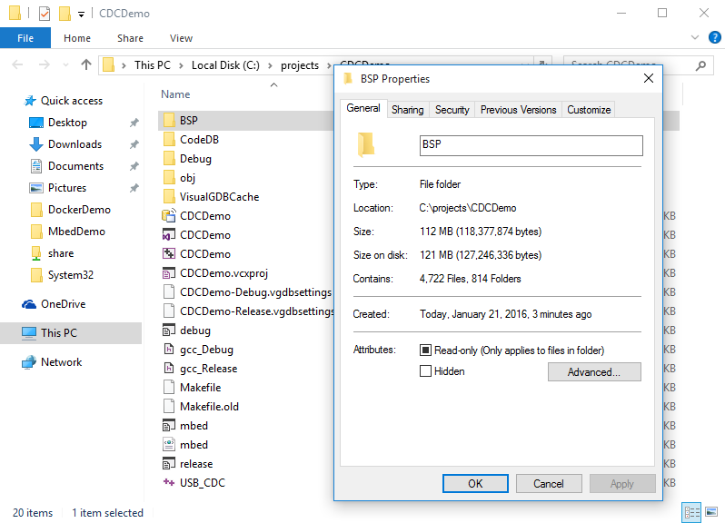
- Note that the mbed framework is huge and hence the size of your project folder will be significantly larger: