Connecting 2 STM32 boards via SPI
This tutorial shows how to connect two STM32 boards using the SPI interface and exchange data between them.
We will connect 2 STM32F4Discovery boards and use the STM32Cube HAL API to configure one board as an SPI master (generating the clock) and the other as an SPI slave (relying on the clock generated by the master). We will then use a logic analyzer to look into the SPI signals and show how to avoid a common synchronization error.
Before you begin, follow our basic STM32 SPI tutorial to get ensure that the SPI on your board works and your logic analyzer can capture and display the SPI signals.
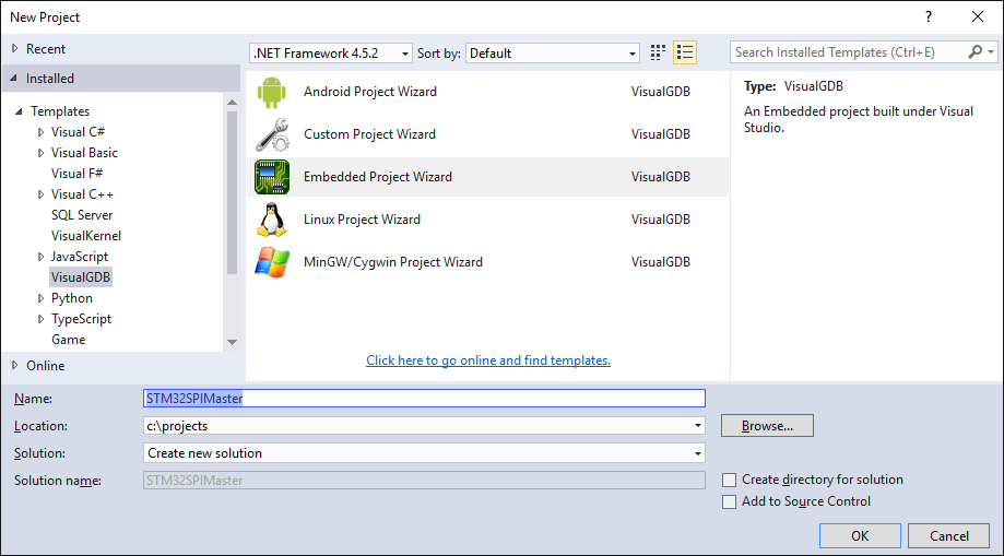
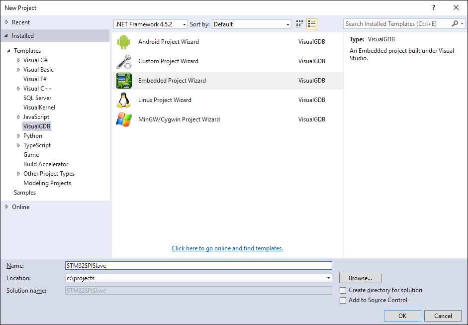
- First we will create the project for the SPI master board. Start Visual Studio and open the VisualGDB Embedded Project Wizard:
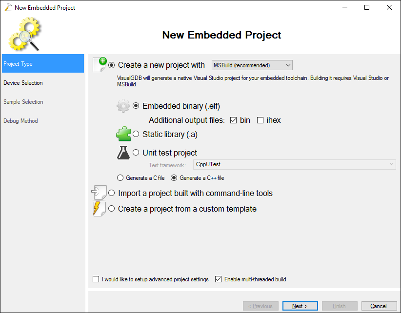
- Proceed with the default project type:
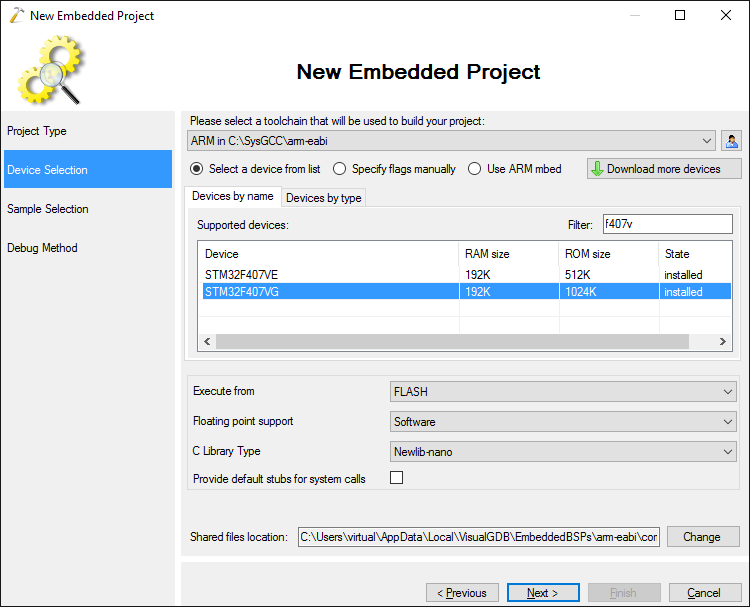
- Select the ARM toolchain and choose your device. For the STM32F4Discovery board shown in this tutorial select STM32F407VG:
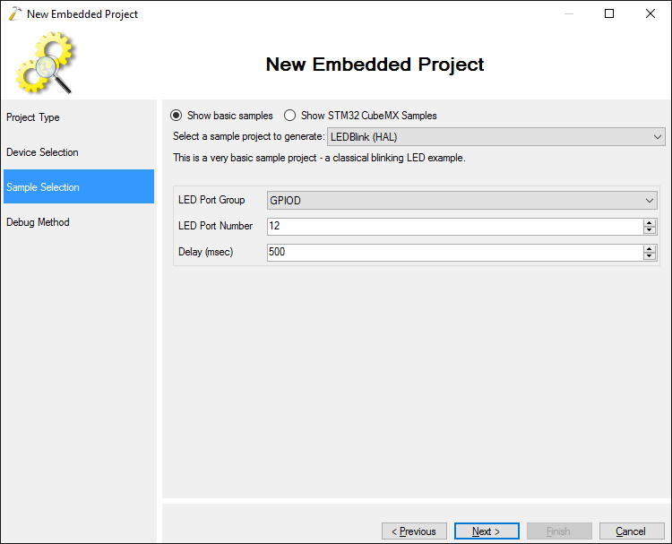
- Proceed with the default “LEDBlink (HAL)” example:
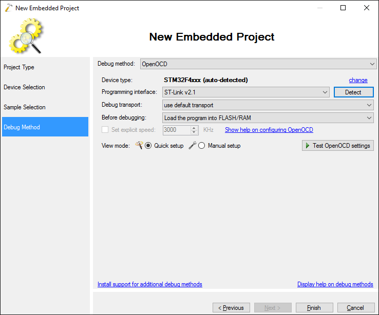
- Select debug settings that match your configuration. For most STM32 devices we recommend using ST-Link via OpenOCD:
- Start another instance of Visual Studio and create another “LEDBlink” project for the board used as the SPI slave:
 Note that in order to debug both boards at the same time, you need to have 2 separate Visual Studio instances.
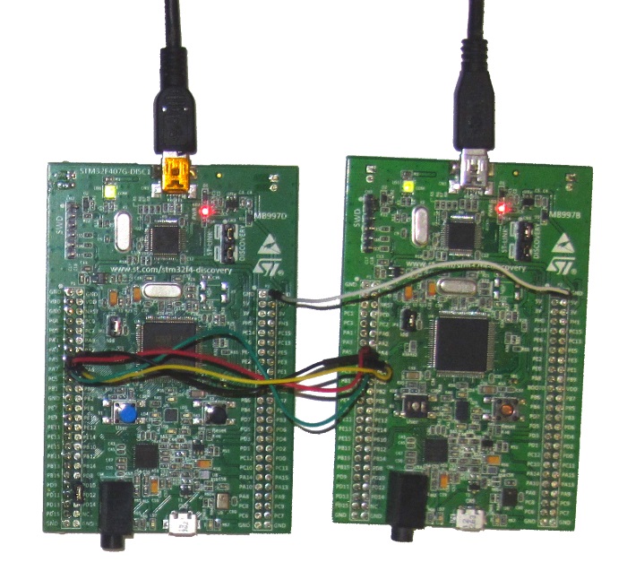
 - Locate the pins corresponding to the SPI signals in your device datasheet (see the basic SPI tutorial for details) and connect them together (MOSI, MISO, SCK and NSS on the master board should be connected to MISO, MOSI, SCK and NSS on the second board). Also connect the ground on the 2 boards:
- Replace the main source file contents in the “Mastet” project with the following:
#include <stm32f4xx_hal.h>

#ifdef __cplusplus
extern "C"
#endif
void SysTick_Handler(void)
{
    HAL_IncTick();
    HAL_SYSTICK_IRQHandler();
}

int main(void)
{
    HAL_Init();

    __GPIOA_CLK_ENABLE();
    __SPI1_CLK_ENABLE();

    static SPI_HandleTypeDef spi = { .Instance = SPI1 };
    spi.Init.BaudRatePrescaler = SPI_BAUDRATEPRESCALER_64;
    spi.Init.Direction = SPI_DIRECTION_2LINES;
    spi.Init.CLKPhase = SPI_PHASE_2EDGE;
    spi.Init.CLKPolarity = SPI_POLARITY_LOW;
    spi.Init.CRCCalculation = SPI_CRCCALCULATION_DISABLED;
    spi.Init.DataSize = SPI_DATASIZE_8BIT;
    spi.Init.FirstBit = SPI_FIRSTBIT_LSB;
    spi.Init.NSS = SPI_NSS_HARD_OUTPUT;
    spi.Init.TIMode = SPI_TIMODE_DISABLED;
    spi.Init.Mode = SPI_MODE_MASTER;
    if (HAL_SPI_Init(&spi) != HAL_OK)
    {
        asm("bkpt 255");
    }

    GPIO_InitTypeDef  GPIO_InitStruct;

    GPIO_InitStruct.Pin       = GPIO_PIN_5 | GPIO_PIN_7;
    GPIO_InitStruct.Mode      = GPIO_MODE_AF_PP;
    GPIO_InitStruct.Pull      = GPIO_PULLUP;
    GPIO_InitStruct.Speed     = GPIO_SPEED_HIGH;
    GPIO_InitStruct.Alternate = GPIO_AF5_SPI1;

    HAL_GPIO_Init(GPIOA, &GPIO_InitStruct);

    GPIO_InitStruct.Pin  = GPIO_PIN_6;
    GPIO_InitStruct.Mode = GPIO_MODE_AF_OD;
    HAL_GPIO_Init(GPIOA, &GPIO_InitStruct);

    GPIO_InitStruct.Pin  = GPIO_PIN_4;
    GPIO_InitStruct.Mode = GPIO_MODE_OUTPUT_PP;
    HAL_GPIO_Init(GPIOA, &GPIO_InitStruct);

    for (int i = 0;; i++)
    {
        int result = 0;
        HAL_GPIO_WritePin(GPIOA, GPIO_PIN_4, GPIO_PIN_RESET);
        HAL_SPI_TransmitReceive(&spi, (uint8_t *)&i, (uint8_t*)&result, sizeof(i), HAL_MAX_DELAY);
        HAL_GPIO_WritePin(GPIOA, GPIO_PIN_4, GPIO_PIN_SET);
        if (result != (i - 1))
        {
            asm("nop");
        }

        HAL_Delay(10);
    }
}
This code configures the SPI in the master mode and then repeatedly sends and receives 32-bit words. Then it compares the received word with the word sent in the previous cycle (the slave board is expected to echo back the received words).
- Replace the main source file contents for the “Slave” project with this:
#include <stm32f4xx_hal.h>

#ifdef __cplusplus
extern "C"
#endif
void SysTick_Handler(void)
{
    HAL_IncTick();
    HAL_SYSTICK_IRQHandler();
}

int main(void)
{
    HAL_Init();

    __GPIOA_CLK_ENABLE();
    __SPI1_CLK_ENABLE();

    static SPI_HandleTypeDef spi = { .Instance = SPI1 };
    spi.Init.BaudRatePrescaler = SPI_BAUDRATEPRESCALER_64;
    spi.Init.Direction = SPI_DIRECTION_2LINES;
    spi.Init.CLKPhase = SPI_PHASE_2EDGE;
    spi.Init.CLKPolarity = SPI_POLARITY_LOW;
    spi.Init.CRCCalculation = SPI_CRCCALCULATION_DISABLED;
    spi.Init.DataSize = SPI_DATASIZE_8BIT;
    spi.Init.FirstBit = SPI_FIRSTBIT_LSB;
    spi.Init.NSS = SPI_NSS_HARD_INPUT;
    spi.Init.TIMode = SPI_TIMODE_DISABLED;
    spi.Init.Mode = SPI_MODE_SLAVE;
    if (HAL_SPI_Init(&spi) != HAL_OK)
    {
        asm("bkpt 255");
    }

    GPIO_InitTypeDef  GPIO_InitStruct;

    GPIO_InitStruct.Pin       = GPIO_PIN_6;
    GPIO_InitStruct.Mode      = GPIO_MODE_AF_PP;
    GPIO_InitStruct.Pull      = GPIO_PULLUP;
    GPIO_InitStruct.Speed     = GPIO_SPEED_HIGH;
    GPIO_InitStruct.Alternate = GPIO_AF5_SPI1;

    HAL_GPIO_Init(GPIOA, &GPIO_InitStruct);

    GPIO_InitStruct.Pin  = GPIO_PIN_5 | GPIO_PIN_7;
    GPIO_InitStruct.Mode = GPIO_MODE_AF_OD;
    HAL_GPIO_Init(GPIOA, &GPIO_InitStruct);

    GPIO_InitStruct.Pin  = GPIO_PIN_4;
    GPIO_InitStruct.Mode = GPIO_MODE_AF_OD;
    HAL_GPIO_Init(GPIOA, &GPIO_InitStruct);

    int input, output = 0;
    for (;;)
    {
        HAL_SPI_TransmitReceive(&spi, (uint8_t *)&output, (uint8_t*)&input, sizeof(input), HAL_MAX_DELAY);
        output = input;
    }
}
This code configures the SPI in the slave mode and simply echoes back the received 32-bit words.
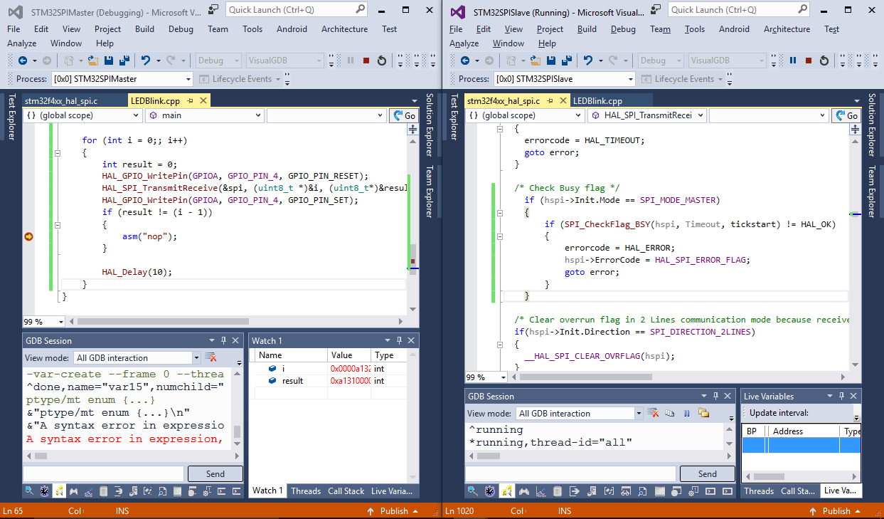
- Set a breakpoint on the “nop” line in the “Master” project and then build and start debugging it. As the slave project is not running yet, the breakpoint should immediately trigger:
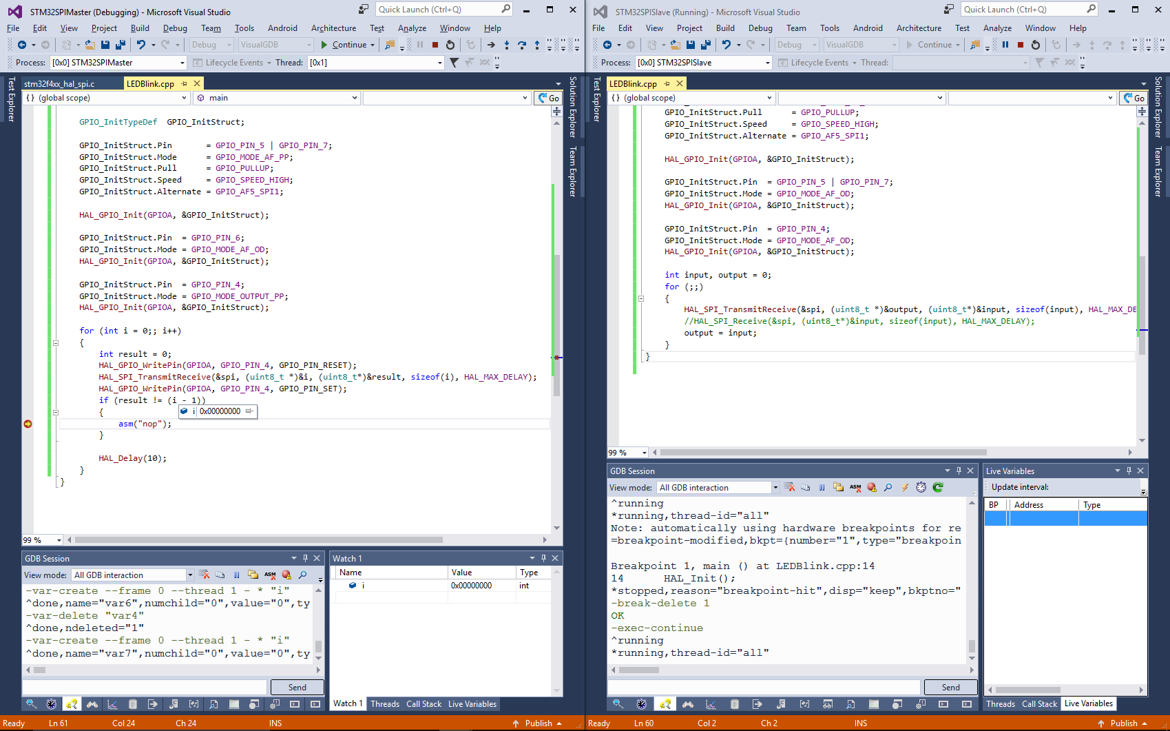
- Now build and start debugging the “Slave” project:
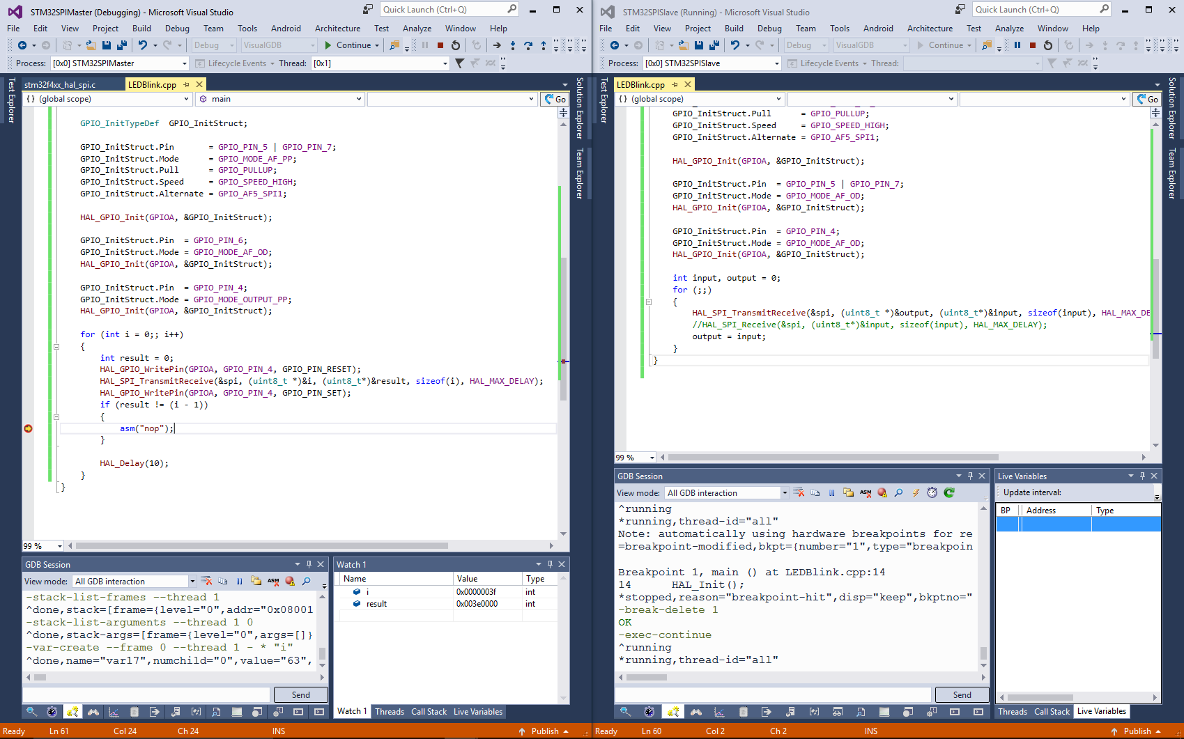 Finally remove the breakpoint in the “Master” project and resume it as well. Both boards should now run in a loop.
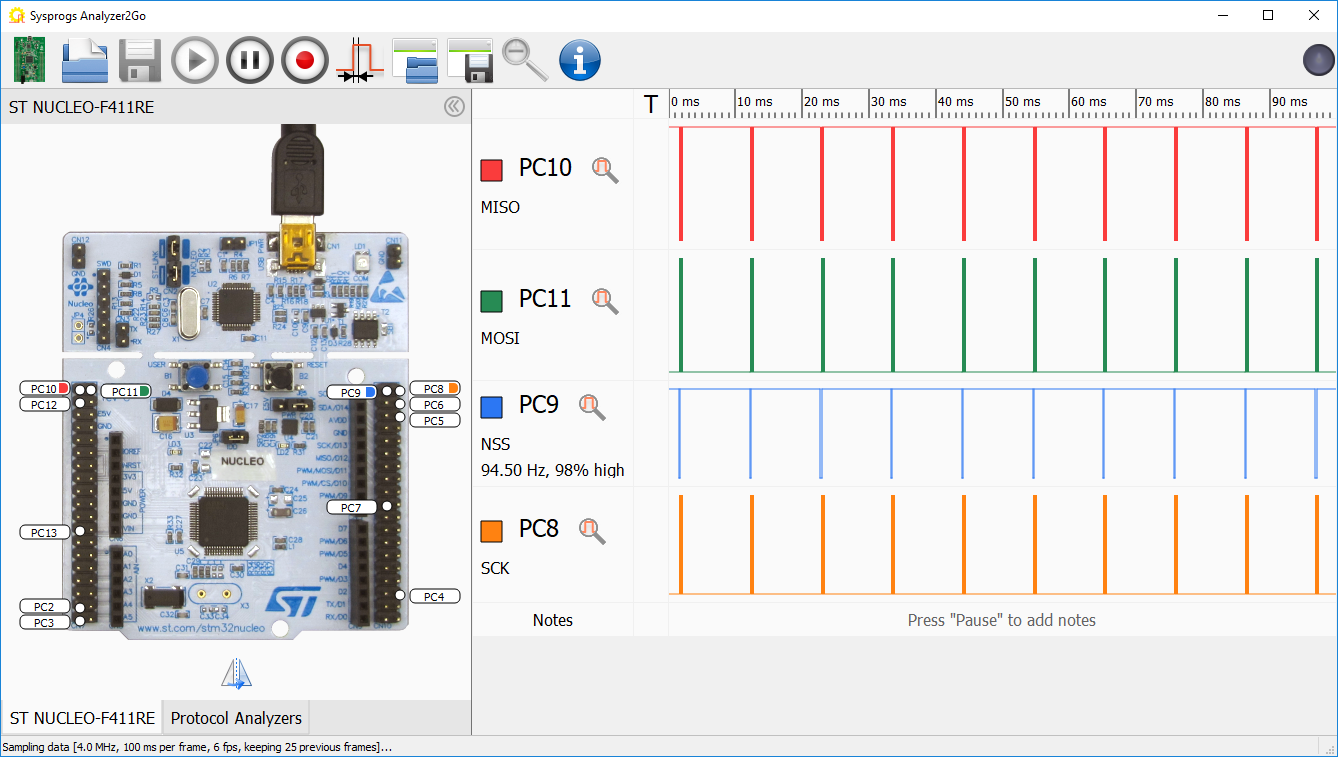
 - Now we will use a logic analyzer to look into the SPI signals. In this tutorial we will use Analyzer2Go that can turn many popular STM32 boards into full-featured logic analyzers. Connect your logic analyzer board to the SPI signals as it is shown in the basic SPI tutorial, enable data capture on them in Analyzer2Go and set labels like MISO, MOSI and SCK for your convenience:
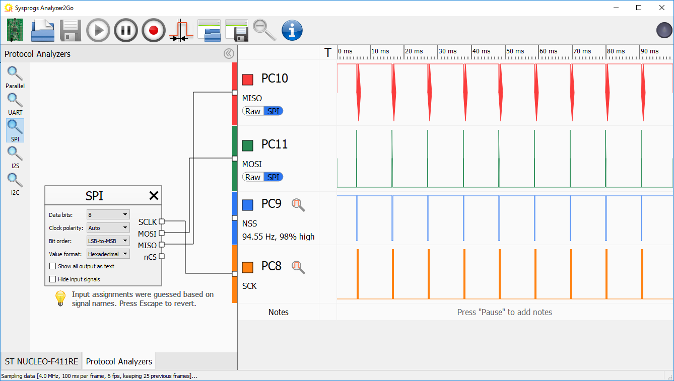
- Go to the Protocol Analyzers tab and add the SPI protocol analyzer to automatically decode the SPI signals:
- Set a breakpoint on the “nop” line in the Master project again. After several seconds to a few minutes it will get triggered:

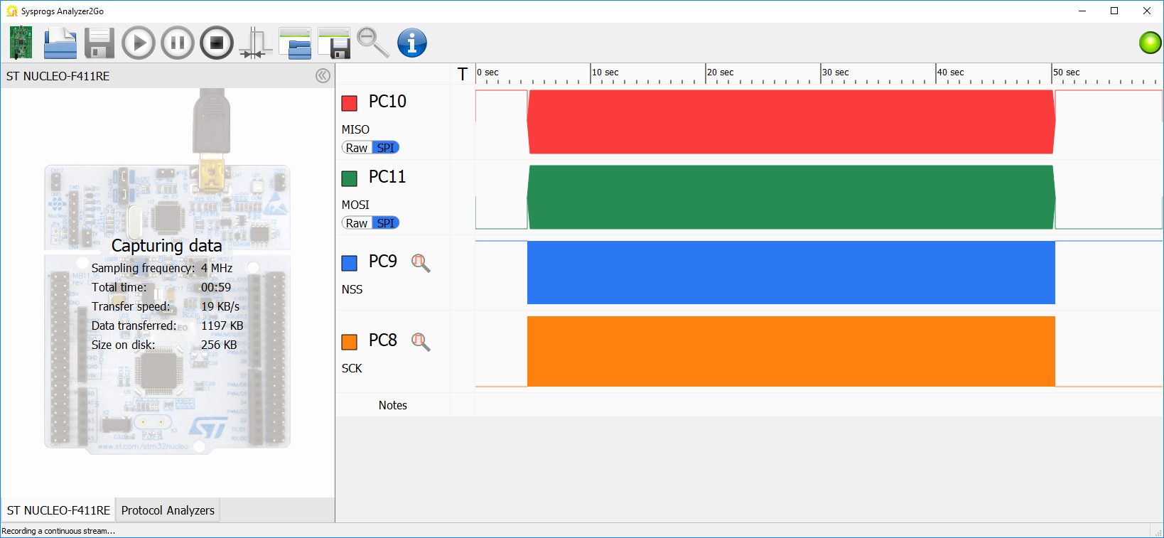
- We will now record the SPI communication prior to the problem and analyze it. Switch back to Analyzer2Go and press “Record”, then resume the “Master” project and wait until the breakpoint triggers again:
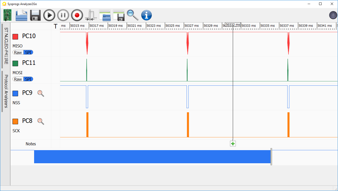
- Zoom into the end of the recorded data until you see individual packets:
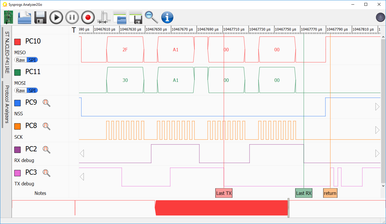
- Double-click on packet before the last one to automatically zoom in:
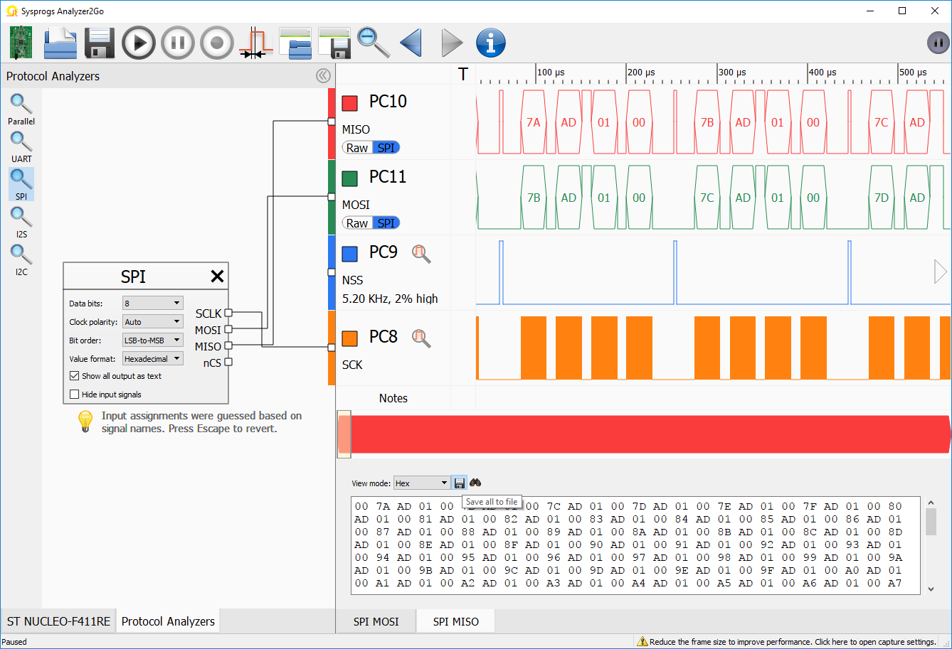
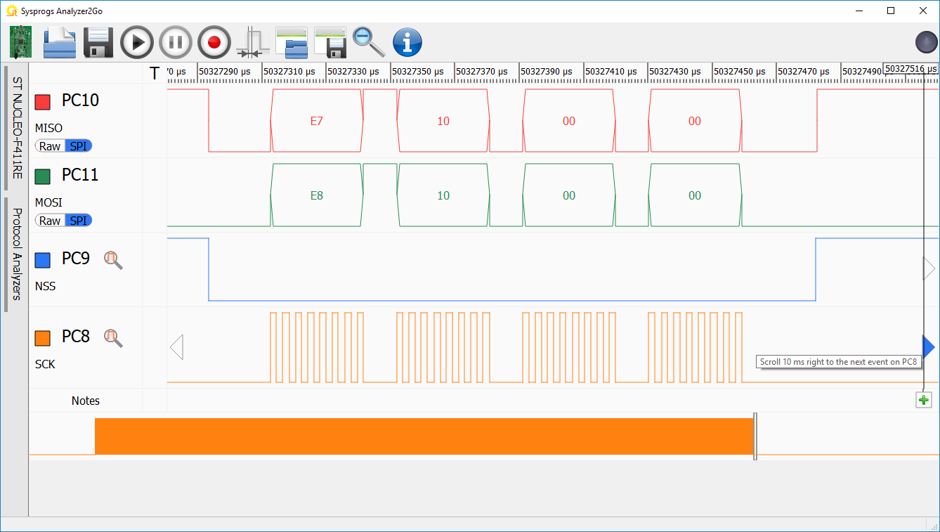 Note how SPI always sends data in both directions. While the MOSI (Master Output/Slave Input) line is used to send a packet from master to slave, the MISO (Master Input/Slave Output) line is already echoing back the data from the previous packet. Click on the right arrow in the “SCK” signal to automatically jump to the next packet.
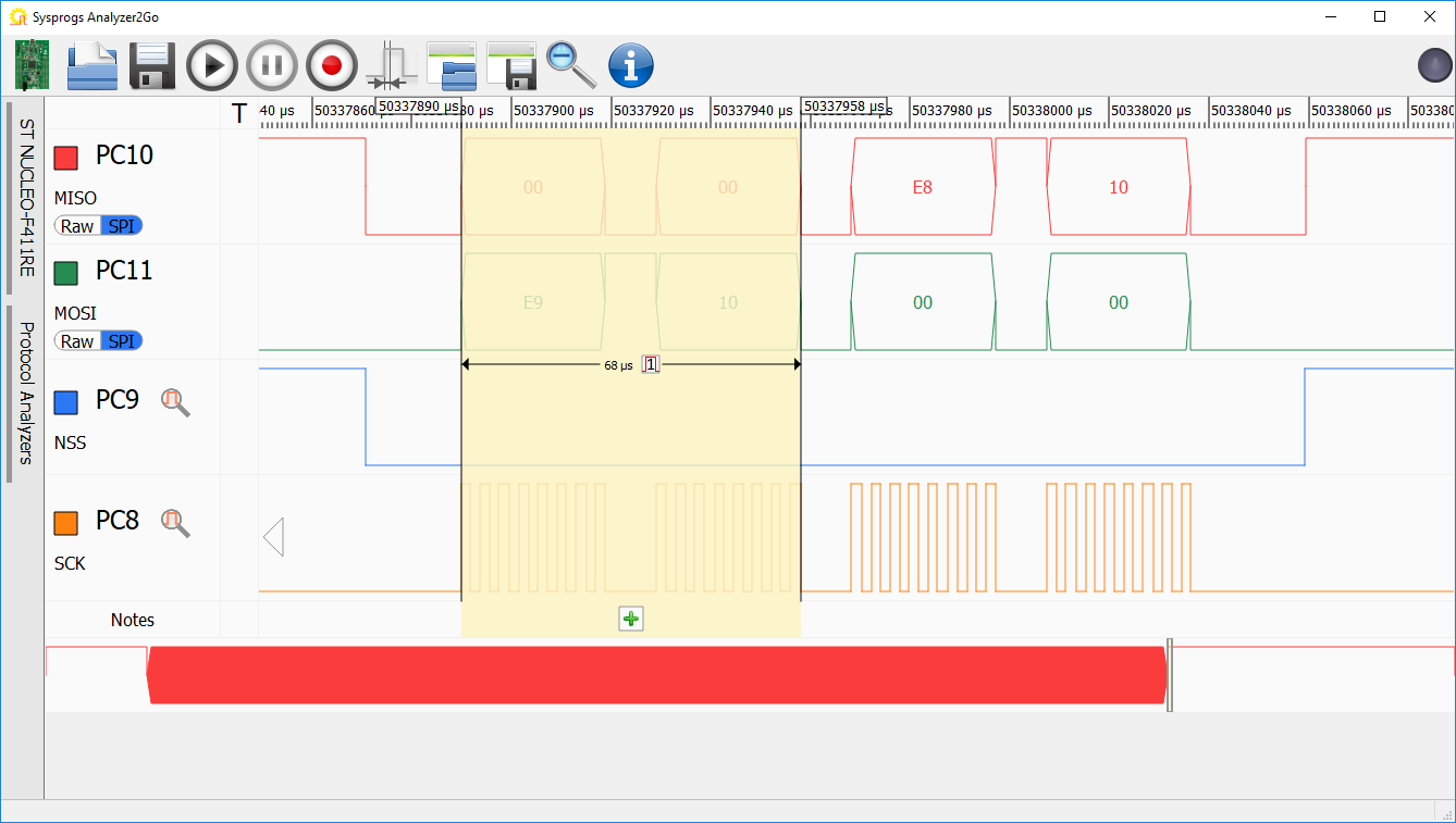
 - The data transferred back in the last packet will look wrong – it will look like 2 extra zero bytes were inserted before the normal reply:
- We will diagnose this by using 2 more pins to track the internal state of the HAL_SPI_TransmitReceive() function. First add the following code before the main loop in the “Slave” project:
    GPIO_InitStruct.Pin  = GPIO_PIN_0 | GPIO_PIN_1;
    GPIO_InitStruct.Mode = GPIO_MODE_OUTPUT_PP;
    HAL_GPIO_Init(GPIOA, &GPIO_InitStruct);
Then add this after the “output = input” line:
        for (int c = 0; c < 4; c++)
            HAL_GPIO_TogglePin(GPIOA, GPIO_PIN_0);
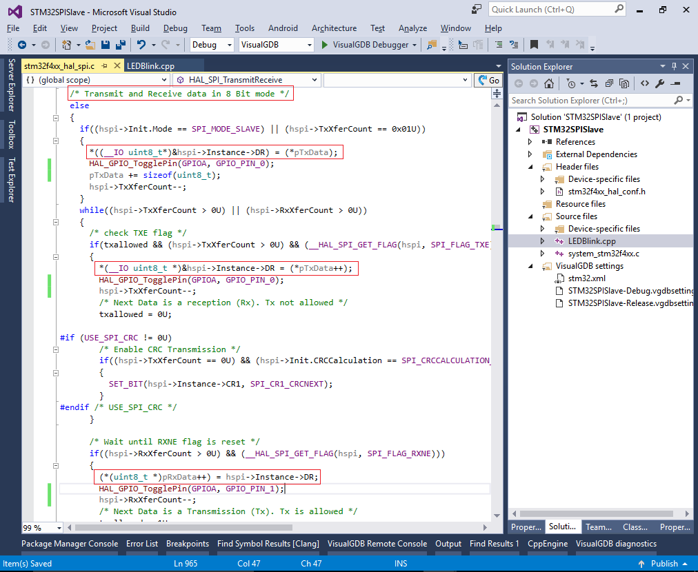
- Finally locate all references to the Instance->DR registers in the 8-bit mode branch of HAL_SPI_TransmitReceive() and add lines toggling PA0 after each write to the DR register (that corresponds to sending a byte) and toggling the PA1 after each read of the DR register (that corresponds to reading received data):
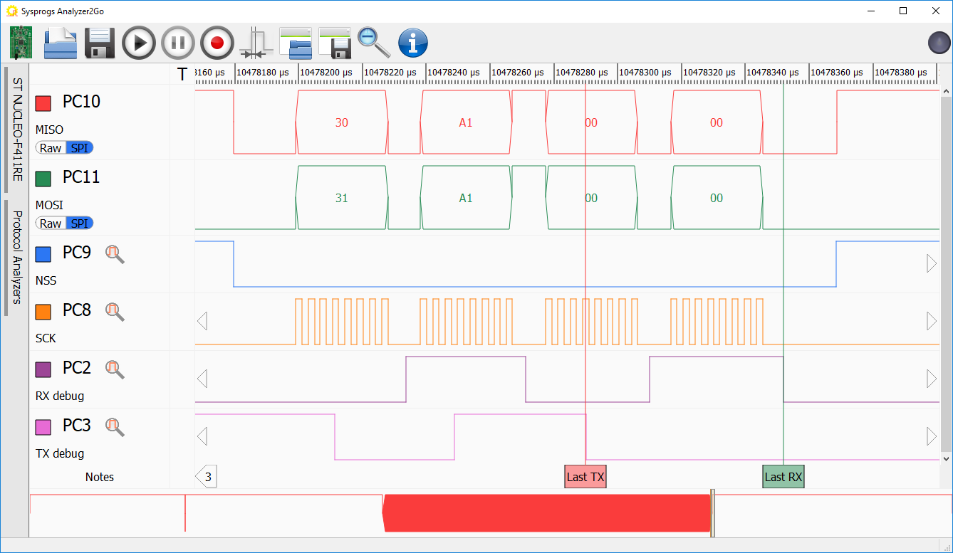
- Connect the PA0 and PA1 pins to the logic analyzer and do another long recording until the problem is reproduced. Note how after each byte sent by the master, the slave gets an RX event (PA1 is toggled) and soon after the last RX event the HAL_SPI_TransmitReceive() function returns (4 fast toggles of PA0):
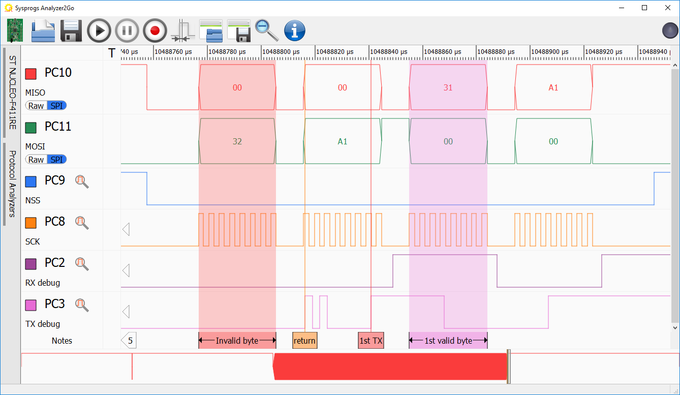
- The packet before the last one looks different: although 4 RX events take place, it looks like the HAL_SPI_TransmitReceive() function never returns:
- This causes the observed behavior in the last packet: the function is stuck until the master sends the first byte (as the slave did not initiate another transfer, the previous value of 00 is repeated), then it returns (missing another byte from the master) and when it’s finally called again, it is 2 bytes too late:
- You can quickly pinpoint the part of the HAL_SPI_TransmitReceive() that gets stuck by toggling the PA0 or PA1 pins in different parts of it and counting the impulses in the logic analyzer. In this example the part responsible for the hang was the SPI_CheckFlag_BSY() call waiting for the BUSY flag to turn off. Normally this check is needed to avoid deactivating the NSS signal before the actual transfer is completed, but it is meaningless in the slave mode. Hence you can fix the problem by patching the HAL_SPI_TransmitReceive() function as follows:
    if (hspi->Init.Mode == SPI_MODE_MASTER)
    {
        if (SPI_CheckFlag_BSY(hspi, Timeout, tickstart) != HAL_OK)
        {
            errorcode = HAL_ERROR;
            hspi->ErrorCode = HAL_SPI_ERROR_FLAG;
            goto error;
        }
    }
 Restart the Slave project and resume the Master project. Confirm that the “nop” breakpoint does not trigger anymore.
 - You can remove the HAL_Delay() call to transfer the data at a higher rate: I
 If you want to programmatically check the consistency of the captured SPI data, use the “Show output as text” checkbox and “Save all to file” button in Analyzer2Go to export the SPI data to a file.
 - The SPI communication code shown in this tutorial has one major drawback: if the slave device starts while the master device is already running, it will not be able to detect the start of the packet properly and may receive incorrectly aligned errors (e.g. instead of [01 00 00 00] [02 00 00 00] it could receive [00 00 00 02] [00 00 00 ..]). We can fix this by creating a modified version of HAL_SPI_TransmitReceive() that will immediately stop receiving a packet if it detects that the PA4 (NSS) pin is high:
bool SPI_TransmitReceiveWithSync(SPI_HandleTypeDef *hspi, uint8_t *pTxData, uint8_t *pRxData, uint16_t Size, uint32_t Timeout)
{
    hspi->ErrorCode   = HAL_SPI_ERROR_NONE;
    hspi->pRxBuffPtr  = (uint8_t *)pRxData;
    hspi->RxXferCount = Size;
    hspi->RxXferSize  = Size;
    hspi->pTxBuffPtr  = (uint8_t *)pTxData;
    hspi->TxXferCount = Size;
    hspi->TxXferSize  = Size;

      /*Init field not used in handle to zero */
    hspi->RxISR       = NULL;
    hspi->TxISR       = NULL;

      /* Check if the SPI is already enabled */
    if ((hspi->Instance->CR1 &SPI_CR1_SPE) != SPI_CR1_SPE)
    {
      /* Enable SPI peripheral */
        __HAL_SPI_ENABLE(hspi);
    }

    int txallowed = 1;
    if ((hspi->Init.Mode == SPI_MODE_SLAVE) || (hspi->TxXferCount == 0x01U))
    {
        *((__IO uint8_t*)&hspi->Instance->DR) = (*pTxData);
        pTxData += sizeof(uint8_t);
        hspi->TxXferCount--;
    }
    while ((hspi->TxXferCount > 0U) || (hspi->RxXferCount > 0U))
    {
      /* check TXE flag */
        if (txallowed && (hspi->TxXferCount > 0U) && (__HAL_SPI_GET_FLAG(hspi, SPI_FLAG_TXE)))
        {
            *(__IO uint8_t *)&hspi->Instance->DR = (*pTxData++);
            hspi->TxXferCount--;
            /* Next Data is a reception (Rx). Tx not allowed */
            txallowed = 0U;
        }

              /* Wait until RXNE flag is reset */
        if ((hspi->RxXferCount > 0U) && (__HAL_SPI_GET_FLAG(hspi, SPI_FLAG_RXNE)))
        {
            (*(uint8_t *)pRxData++) = hspi->Instance->DR;
            hspi->RxXferCount--;
            /* Next Data is a Transmission (Tx). Tx is allowed */
            txallowed = 1U;
        }

        if (HAL_GPIO_ReadPin(GPIOA, GPIO_PIN_4))
            return false;
    }
    return true;
}