Developing Renesas RL78 Projects with Visual Studio
This tutorial shows how to use VisualGDB to develop and debug C/C++ projects targeting the RL78 devices with Visual Studio. We will create a basic project for the RL78/I1A DC LED board (EZ-0012) that will turn on the on-board LEDs using the code generated by the Applilet tool from Renesas and will show how to build and debug the project with Visual Studio.
Before you begin, download and install the following tools:
- Visual Studio
- VisualGDB 5.4 Preview 4 or later
- Renesas E2 Studio
- RL78 GCC Toolchain (installed via the E2 Studio installer)
- Applilet EZ for HCD
Once all the necessary tools are installed, ensure you can create and debug a basic project using the Renesas E2 Studio. Once you confirm that the E2-Studio-based debug works, take a note of the GDB stub command line shown in the debug console: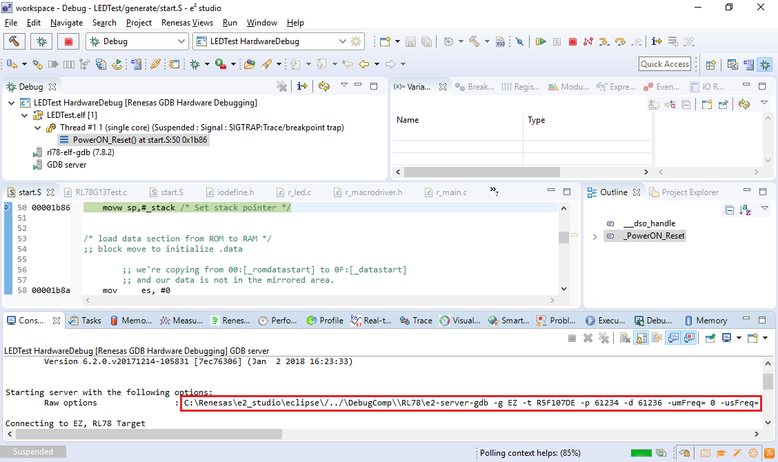
The command line may vary depending on the exact debug tool you are using. We will show later in this tutorial how to ensure that VisualGDB will use the same command line when debugging your RL78-based project.
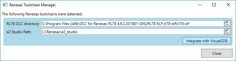
- Download and run the RenesasToolchainManager.exe tool. Ensure is shows the correct paths to the RL78 toolchain and the E2 Studio and click “Integrate with VisualGDB”:
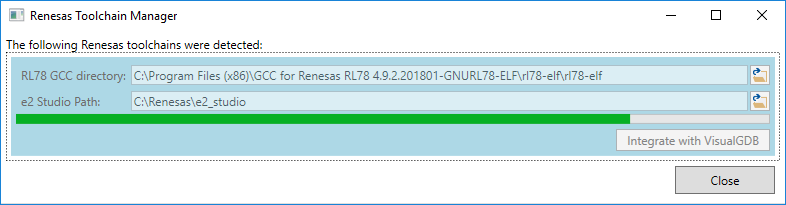
- The tool will scan the E2 Studio directory for supported device definitions and will automatically convert them to a VisualGDB-compatible format. It will also convert peripheral register definitions and will register the E2 Studio gdb server as a supported debug method. This might take 1-5 minutes depending on your system performance:
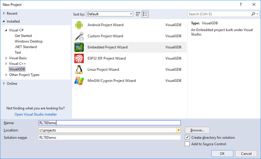
- Start the VisualGDB Embedded Project Wizard:
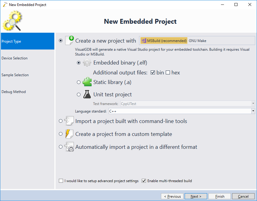
- On the first page of the wizard select “Create a new project” -> “MSBuild”:
- On the next page select the Renesas RL78 toolchain and choose your device from the list. If the toolchain is not shown, ensure you restart Visual Studio after running the Renesas Toolchain Manager.
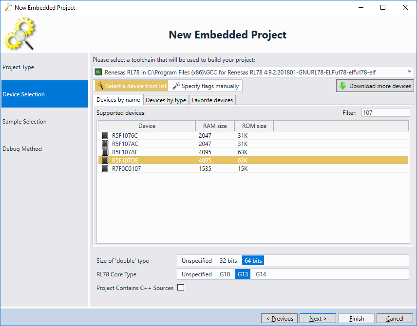 If you are planning to use C++ source files, check the corresponding checkbox in the device settings.
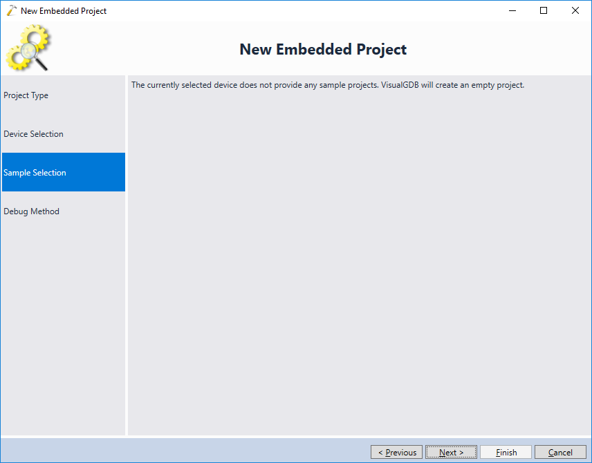
 - The imported Renesas toolchain will not contain any project samples. Click “Next” on the Sample Selection page to proceed with creating an empty project:
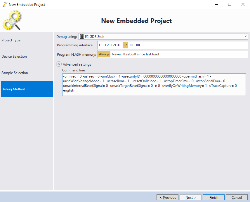
- On the last page of the wizard select your debug interface. The RL78/I1A DC LED board contains an EZ debug module (ensure you activate it using the on-board switches), so we will select it in this tutorial:
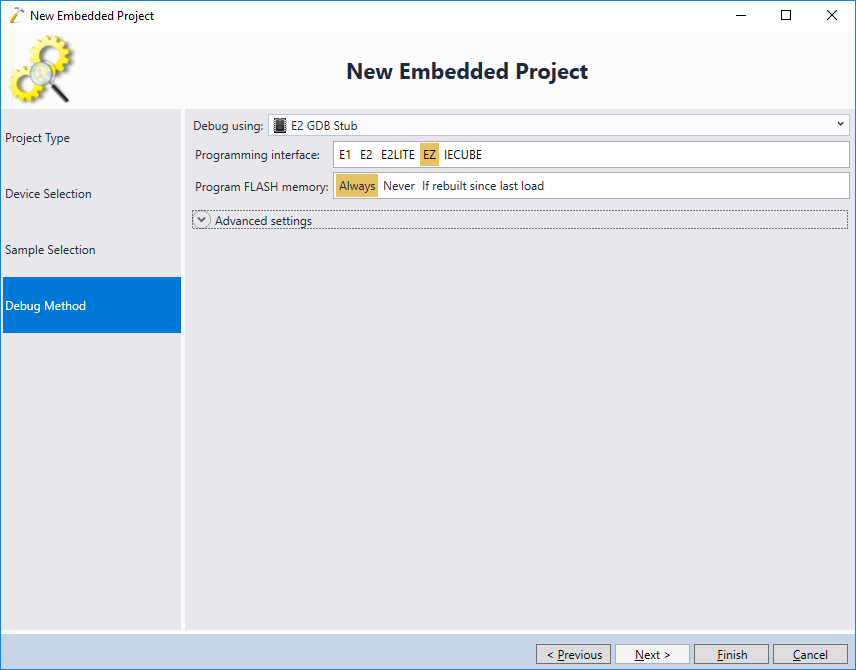
- If you are using any other board, expand the “Advanced Settings” field and copy the gdb stub command line obtained from the E2 Studio into VisualGDB, removing the -g, -t, -p and –d flags and the corresponding arguments:
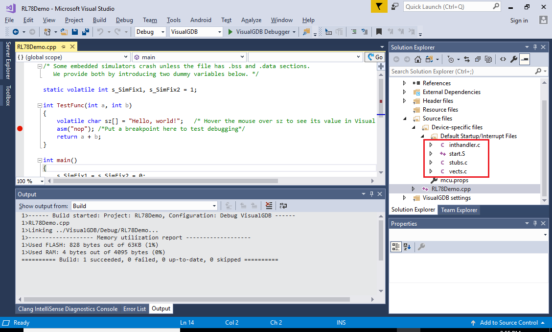
- Press “Finish” to create the project. VisualGDB will generate a basic project including a linker script, default interrupt handlers and I/O register definitions for the selected device:
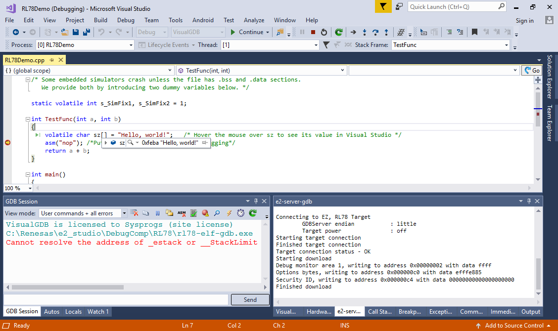
- Set a breakpoint on the “nop” line and press F5 to start debugging. VisualGDB will launch the E2 Studio gdb stub, program the FLASH memory and start the program. Once the breakpoint is hit, you will be able to debug the program as usual:
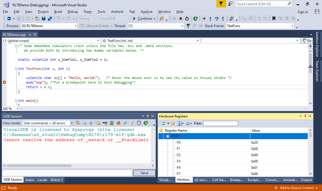
- The toolchain importing process automatically converted the peripheral register definitions to the VisualGDB format, so you will be able to view them via Debug->Windows->Hardware Registers:
- Now we will show how to import a basic project generated by the Applilet EZ for HCD tool. Launch the tool and create a basic project for your board, then click “Generate Code”:
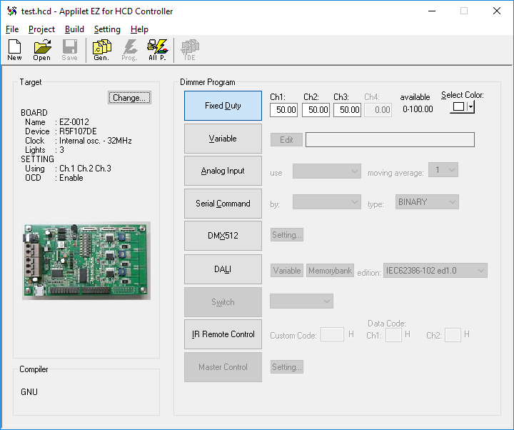 The generated code will normally be available in the <Documents>\Applilet EZ HCD\Projects folder, even if the tool crashes.
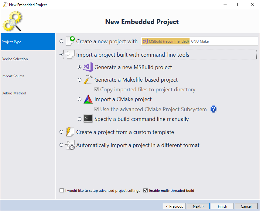
 - Open the VisualGDB Embedded Project Wizard again and select “Import a project built with command-line tools” on the first page:
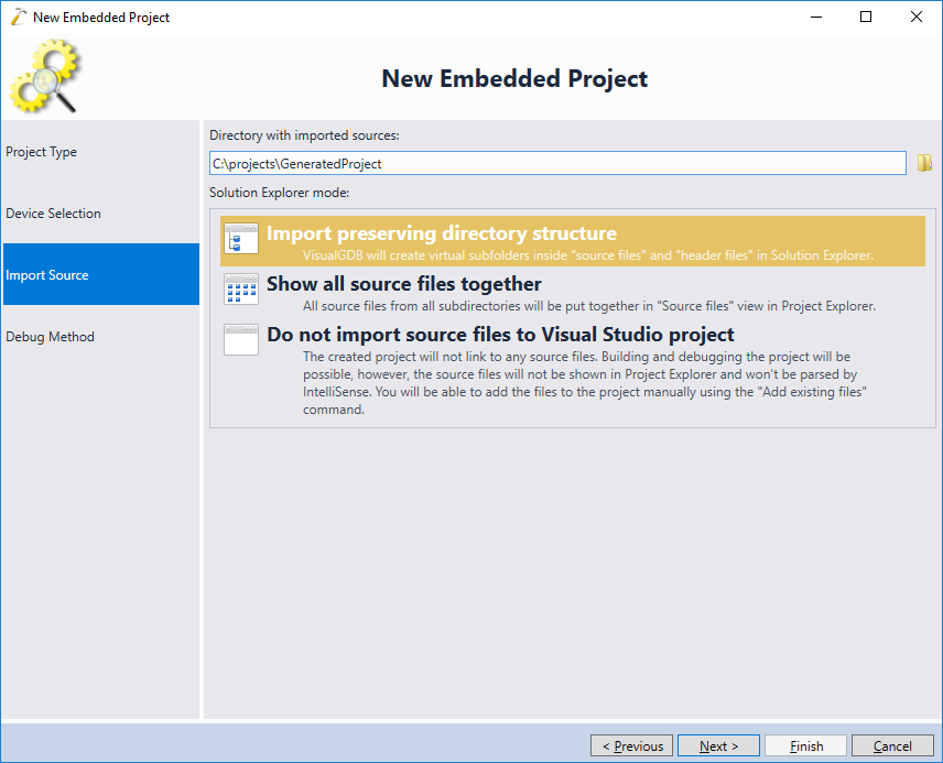
- On the next page select the same toolchain/device and proceed to the Import Source page. Then point the wizard to the location of the generated project:
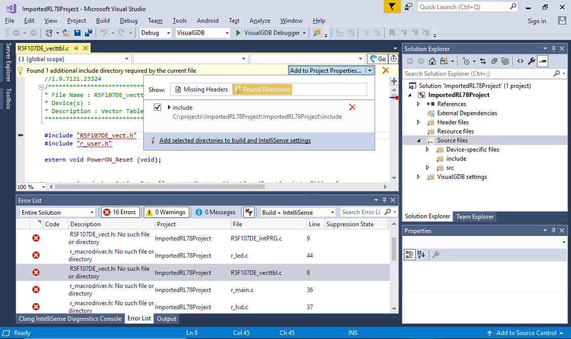
- Proceed with the same debug settings as before and click “Finish” to generate the project. If you try building it initially, VisualGDB will fail due to missing header files:
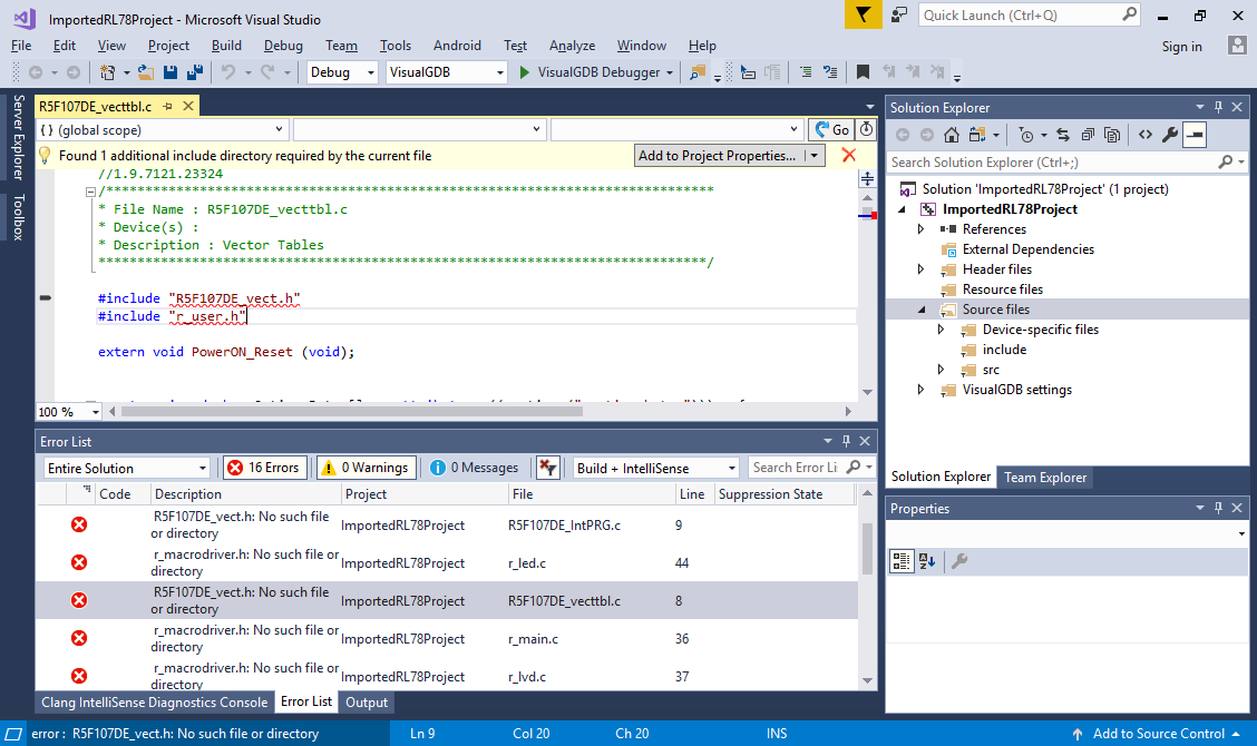
- Once you open any of the source files with the error message, VisualGDB will automatically locate them and suggest adjusting the settings. Click “Add selected directories to build and IntelliSense Settings”:
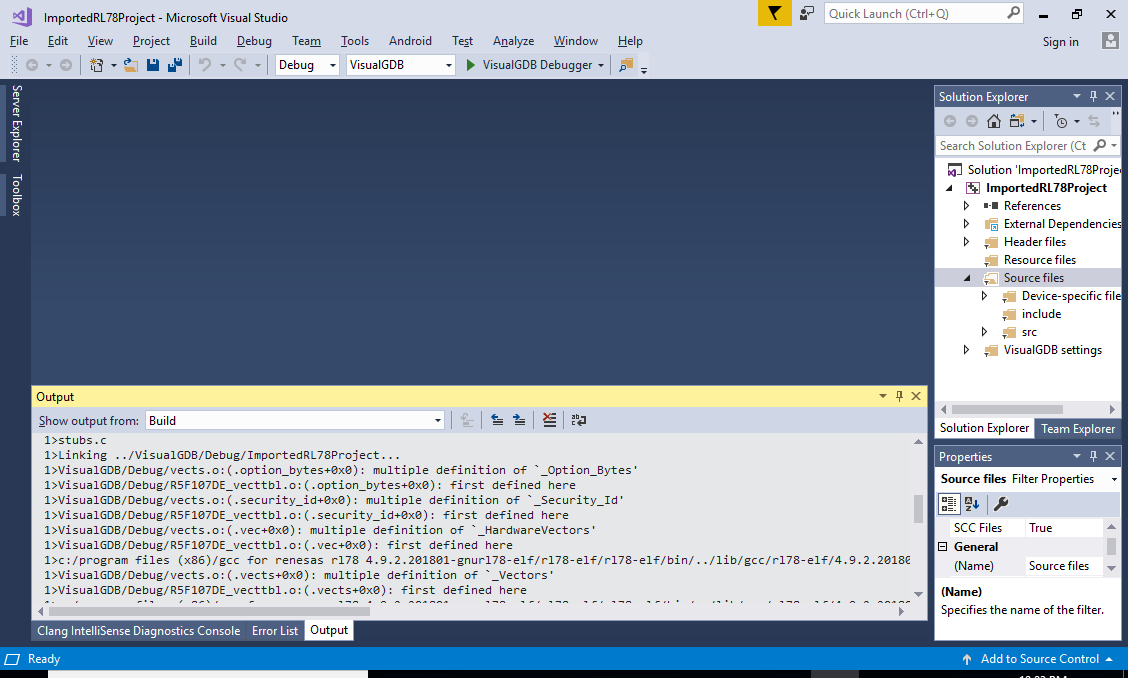
- If you build the project now, it will fail due to multiple definitions of several symbols:
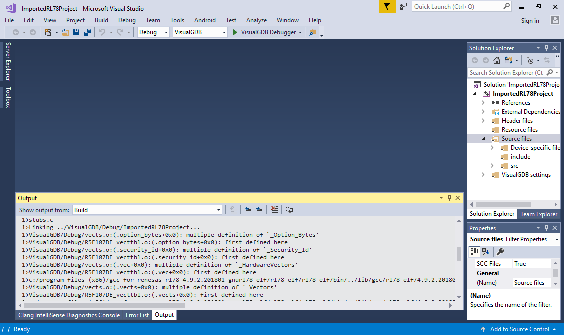
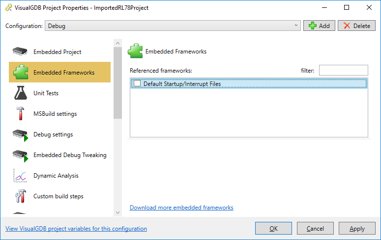
- This happens because the Applilet tool generates independent copies of the files imported from E2 Studio. Remove the reference to the default startup files via the Embedded Frameworks page of VisualGDB Project Properties:
- Before you can successfully build the project, you will need to resolve one last error – missing reset handler:
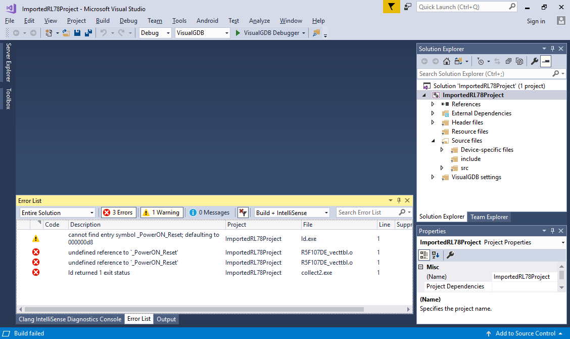
- It happens as VisualGDB doesn’t automatically import assembly files when using default settings. Locate the reset_program.asm file in the generated project folder, change its extension to .S so that gcc can handle it properly (note the uppercase ‘S’) and add it to the project:
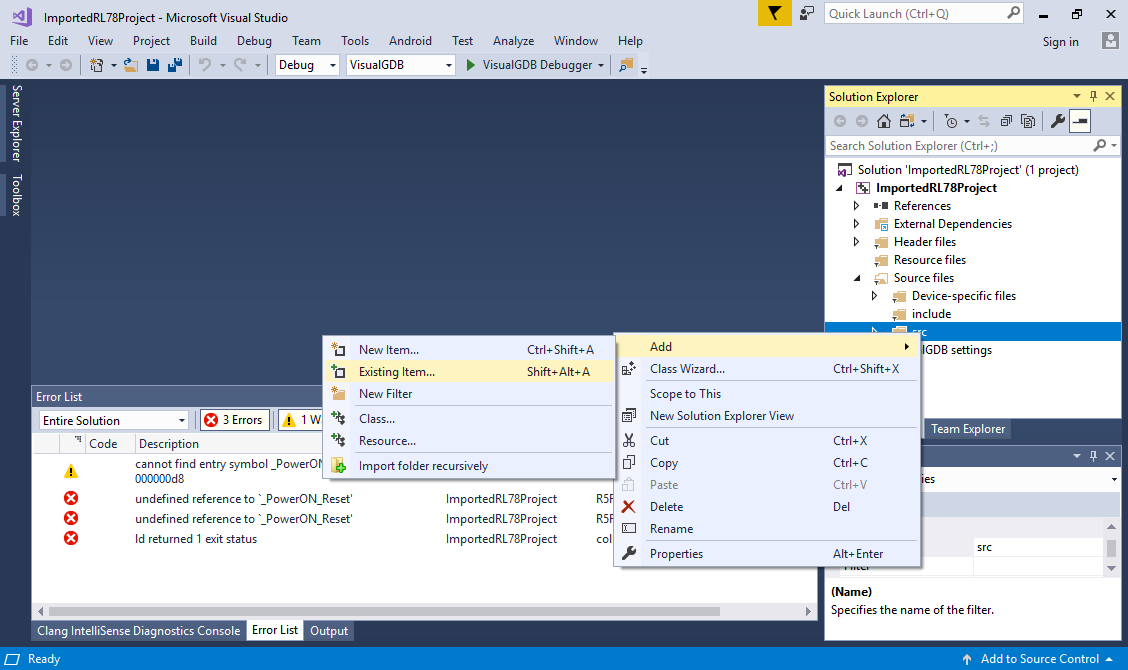
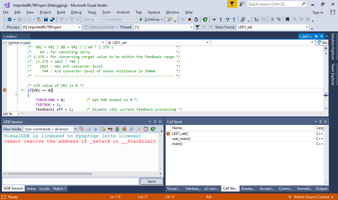
- Now the project will build successfully and running it will turn on the on-board LEDs. You can step through the code responsible for setting various hardware registers by setting a breakpoint in the LED1_set() function and then using the regular “step over” command: