Using the UART interface of the msp430 devices
This tutorial demonstrates how to make a basic project utilizing the UART interface of an msp430 chip and to debug it using the raw terminal included in VisualGDB. We will create a basic project that reads the room temperature using the msp430’s built-in temperature sensor and sends it over UART.
Before we begin, ensure that VisualGDB 4.2 or later is installed. Note that to use the raw terminal you will need the Custom edition or higher.
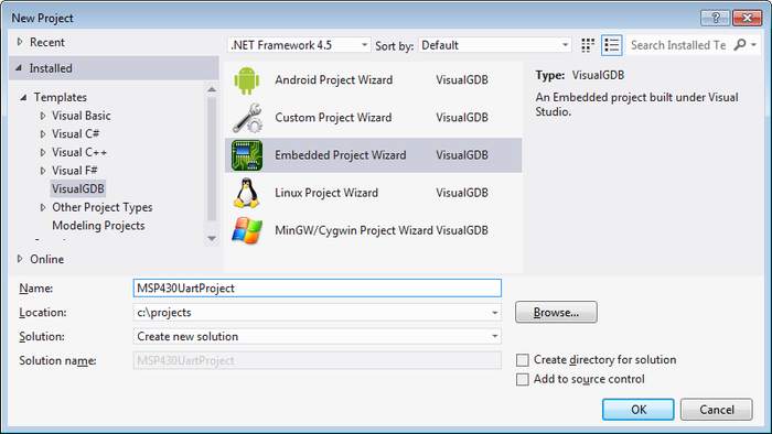
- Start Visual Studio. Go to File->New->Project and select “VisualGDB Embedded Project Wizard”:
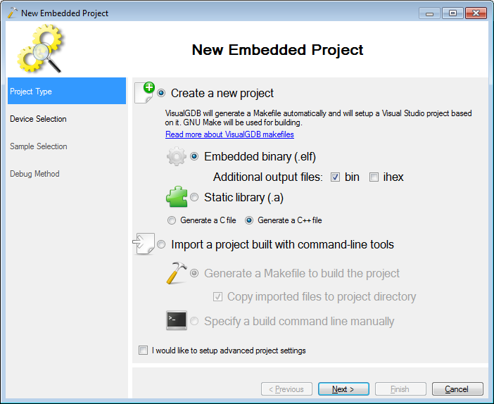
- Proceed with the default settings on the first page:
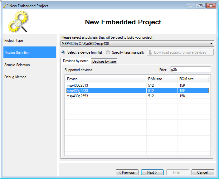
- On the next page select the msp430 toolchain. If the toolchain is not installed yet, VisualGDB will download and install it automatically. Select your device from the list. If you are using the msp430 launchpad board, use the msp430g2553 device:
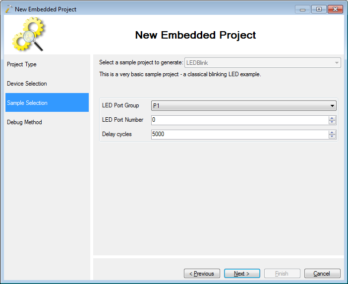
- As we will be replacing the default example with our UART code, there is no need to change the default example settings:
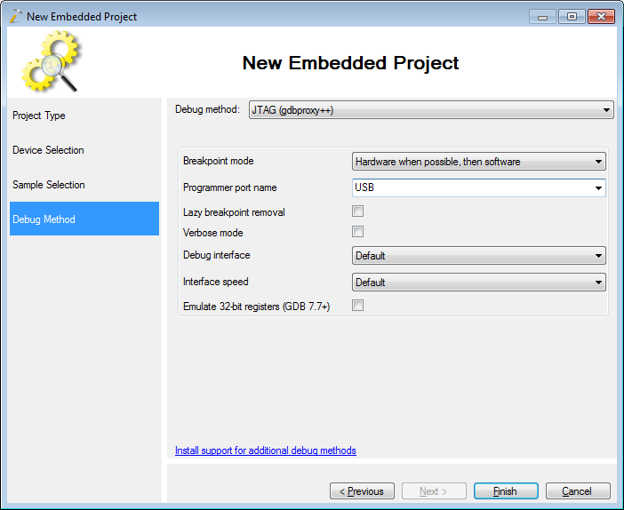
- Select “JTAG (gdbproxy++)” as the debug method and press “Finish” to create your project:
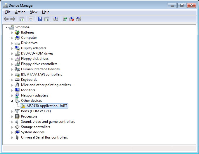
- Connect your msp430 board to the computer. The msp430 Launchpad board comes with an integrated USB-to-UART adapter that supports baud rates up to 9600. Open Device Manager to find out the COM port number of the msp430 board. Note that if you have not used the adapter before, the drivers won’t be installed:
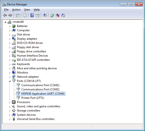
- The drivers for the UART are located in <msp430 toolchain directory>\drivers. After you install them the UART device will have a port number assigned to it:
- Add the following code to the main file of the project you created:
class UART { public: staticvoid Configure(unsigned divider, unsignedchar firstModulation, unsignedchar secondModulation) { UCA0CTL1 = UCSSEL_2; UCA0BR0 = divider & 0xFF; UCA0BR1 = divider >> 8; UCA0MCTL = ((firstModulation & 0xF) << 4) | ((secondModulation & 0x7) << 1); UCA0CTL1 &= ~UCSWRST; } staticbool HasData() { return IFG2 & UCA0RXIFG; } staticunsignedchar Read() { while (!(IFG2 & UCA0RXIFG)); return UCA0RXBUF; } staticvoid Write(unsignedchar byte) { while (!(IFG2 & UCA0TXIFG)); UCA0TXBUF = byte; } }; - To test the UART we will make a basic program that will set the main clock to 1 MHz, and set the UART divider to 104 resulting in a 9600 baud rate. It will then read UART input byte-by-byte, add 1 to each byte and echo it back:
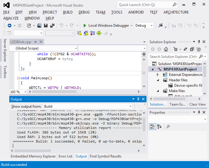
WDTCTL = WDTPW | WDTHOLD; DCOCTL = 0; BCSCTL1 = CALBC1_1MHZ; DCOCTL = CALDCO_1MHZ; P1SEL |= BIT1 | BIT2; P1SEL2 |= BIT1 | BIT2; UART::Configure(104, 1, 0); for (;;) { unsignedchar byte = UART::Read(); UART::Write(byte + 1); } - Build your project by pressing Ctrl-Shift-B:
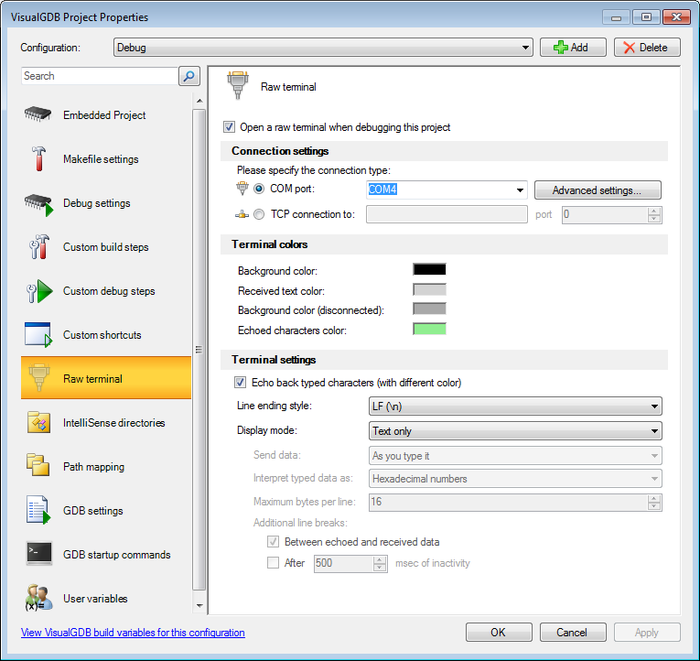
- Right-click on the your project node in Solution Explorer, select “VisualGDB Project Properties”, go to the Raw Terminal page and enable the terminal on the msp430 COM port:
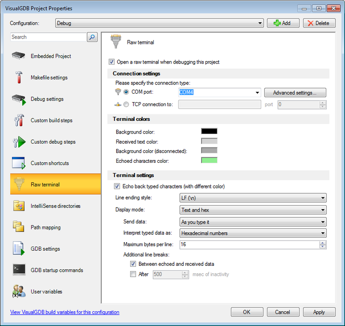 Ensure you select the “text and hex” view and enable the character echoing
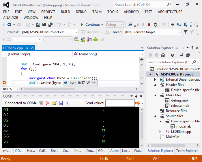
 - Start debugging by pressing F5. Try entering some hexadecimal numbers in the terminal and see how the msp430 board increases them and sends them back. You can set a breakpoint in your code to step through it as well:
- Now we will add the code that will use the msp430g2553’s ADC to read the value from the built-in temperature sensor. First of all we will add a basic ADC wrapper class:
class ADC { public: staticvoid Setup() { ADC10AE0 = 0; ADC10CTL0 &= ~ENC; ADC10CTL0 = SREF_1 | REFON | ADC10ON; } static unsignedint DoSingleMeasurement(int channelNumber) { ADC10CTL0 &= ~ENC; ADC10CTL1 = ((channelNumber & 0xF) << 12) | ADC10DIV_7; ADC10CTL0 |= ENC | ADC10SC; while (!(ADC10CTL0 & ADC10IFG)) { ; } return ADC10MEM; } }; - Replace the old for() loop with the new one reading ADC values, computing averages and sending them via UART:
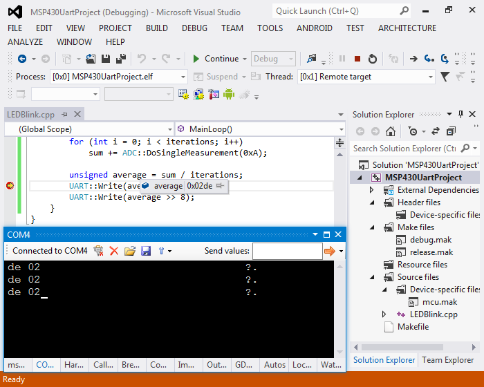
ADC::Setup(); for (;;) { constint iterations = 16384; unsigned long sum = 0; for (int i = 0; i < iterations; i++) sum += ADC::DoSingleMeasurement(0xA); unsigned average = sum / iterations; UART::Write(average); UART::Write(average >> 8); } - Start debugging and look at the terminal. You will see how your msp430 device is reporting the ADC readouts one-by-one. You can configure the terminal to automatically insert line breaks after some period (e.g. 100 ms) to simplify telling apart different values:
 The code can be converted to centigrade temperature using the following formula:
tempC = (value * 1.5 / 1024 - 0.986) / 0.00355
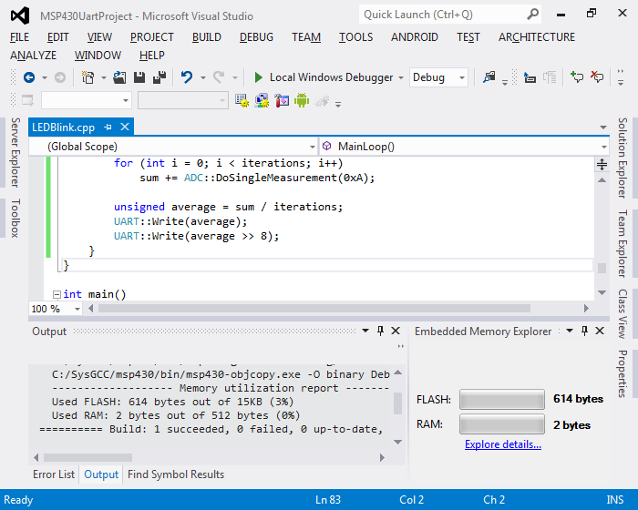
- The value of 0x2de shown in this example corresponds to 25.1 degrees. A very basic msp430 thermometer is done! You can use the Embedded Memory Explorer window to see that the size of our firmware is only 614 bytes and can be further reduced to 328 bytes if you build the optimized release configuration:
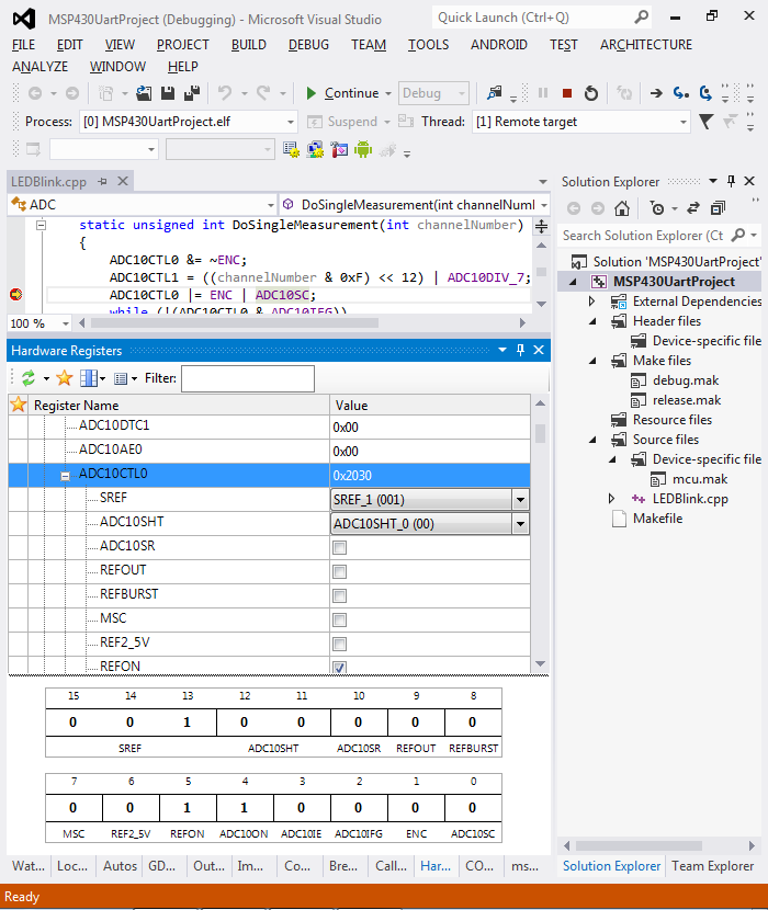
- You can experiment with different ADC modes without recompiling your program. Simply use the Hardware Registers window to view/modify the values of the ADC registers:
- We will now add some extra user-friendliness to our thermometer project. First of all, we will use the temperature sensor calibration values to get a more accurate reading. Second of all, we will compute the centigrade value on the device and print it as text:
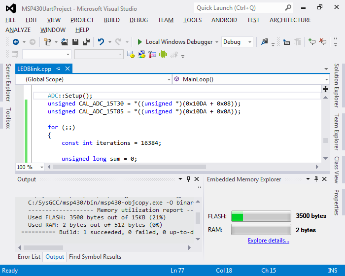
unsigned CAL_ADC_15T30 = *((unsigned *)(0x10DA + 0x08)); unsigned CAL_ADC_15T85 = *((unsigned *)(0x10DA + 0x0A)); for (;;) { constint iterations = 16384; unsignedlong sum = 0; for (int i = 0; i < iterations; i++) sum += ADC::DoSingleMeasurement(0xA); unsigned average = sum / iterations; int tempCx10 = ((long)average - CAL_ADC_15T30) * (85 - 30) * 10 / (CAL_ADC_15T85 - CAL_ADC_15T30) + 300; printf("%d.%d C\r\n", tempCx10 / 10, tempCx10 % 10, (unsigned)(sum / iterations)); } - In order for the printf() to work we need to include the <stdio.h> header file and define the putchar() function that is responsible for sending the output of printf() to the user:
#include<stdio.h> extern"C"int putchar(int ch) { UART::Write(ch); } - Build your project. You will see how the amount of used FLASH memory jumped up to 3500 bytes:
- Click on the “Explore details” link. You will see how 60% of the FLASH footprint comes from the vuprintf.c source file and that the code written in this example (in LEDBlink.cpp) only contributes 14%:
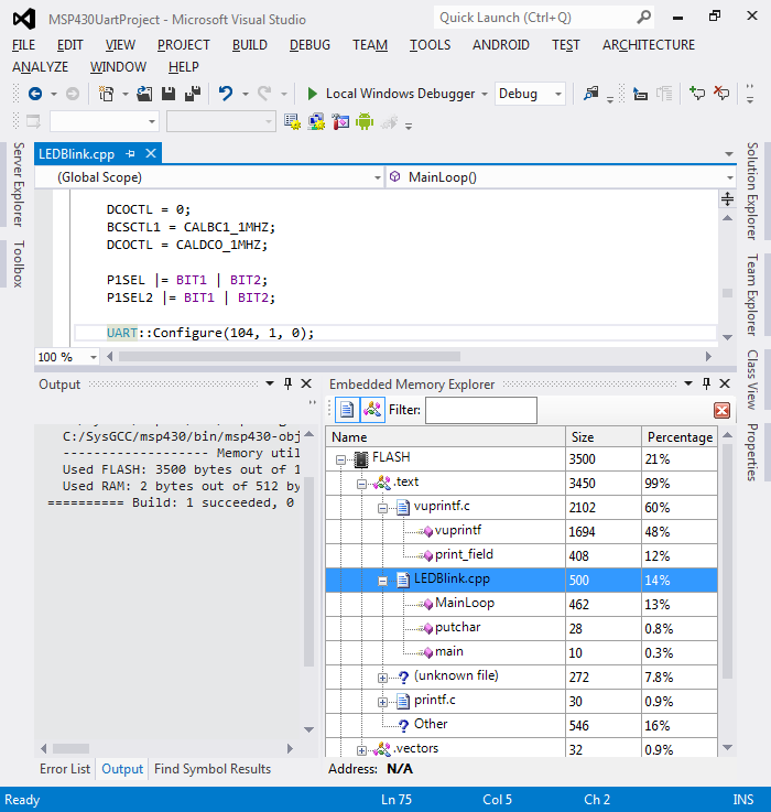 You can double-click on your functions to navigate to their definition in source code.
 - Finally we will test our new firmware. To do that, switch the raw terminal to the text mode:
- Then press F5 to start debugging and check the output in the raw terminal window:
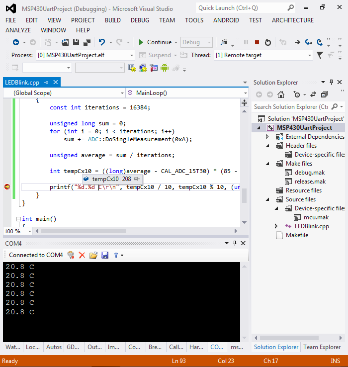


The formatted output is more user-friendly, however it requires more than 5x the FLASH size due to large printf()-related functions.