Porting embedded code with mbed and VisualGDB
This tutorial shows how to create portable embedded applications with the ARM mbed framework and VisualGDB. We will show how to create a basic multi-threaded application for the STM32F4Discovery and then quickly port it to the Freescale FRDM-KL25Z board.
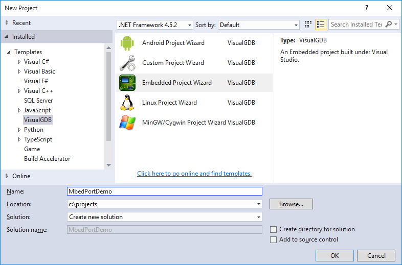
- Begin with starting Visual Studio and opening the VisualGDB Embedded Project wizard:
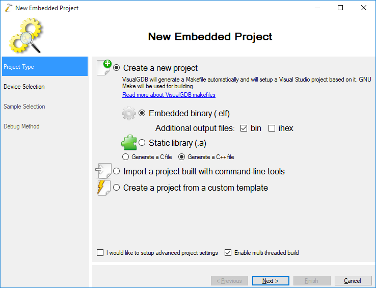
- Continue with the default “Create a new project” setting on the first page:
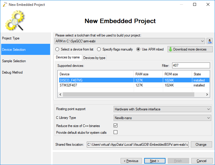
- On the next page select the first device you want to target. We will start with the STM32F4Discovery board, so we select DISCO_F407 here. It is recommended to select newlib-nano as the C library to reduce the size of your binary:
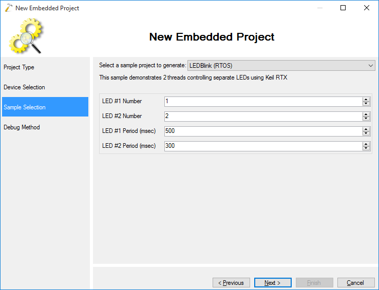
- On the next page select “LEDBlink (RTOS)” sample and keep the default LED numbers:
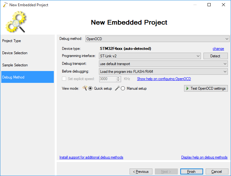
- On the last page select OpenOCD as the debug method:
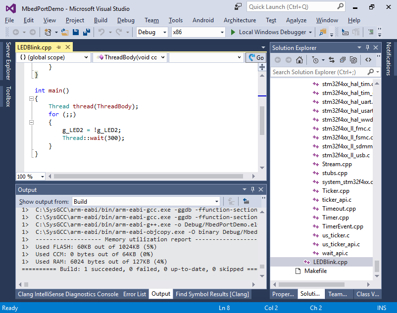
- Press Finish to generate your project. Build it by pressing Ctrl-Shift-B:
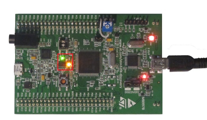
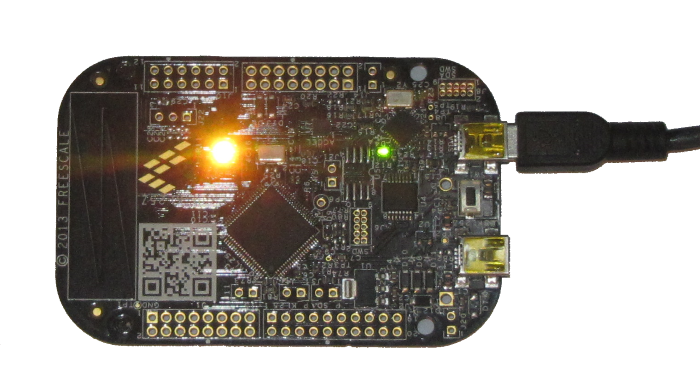
- Hit F5 to start debugging. Observe how the two LEDs begin to blink with different periods as 2 independent threads are controlling them:
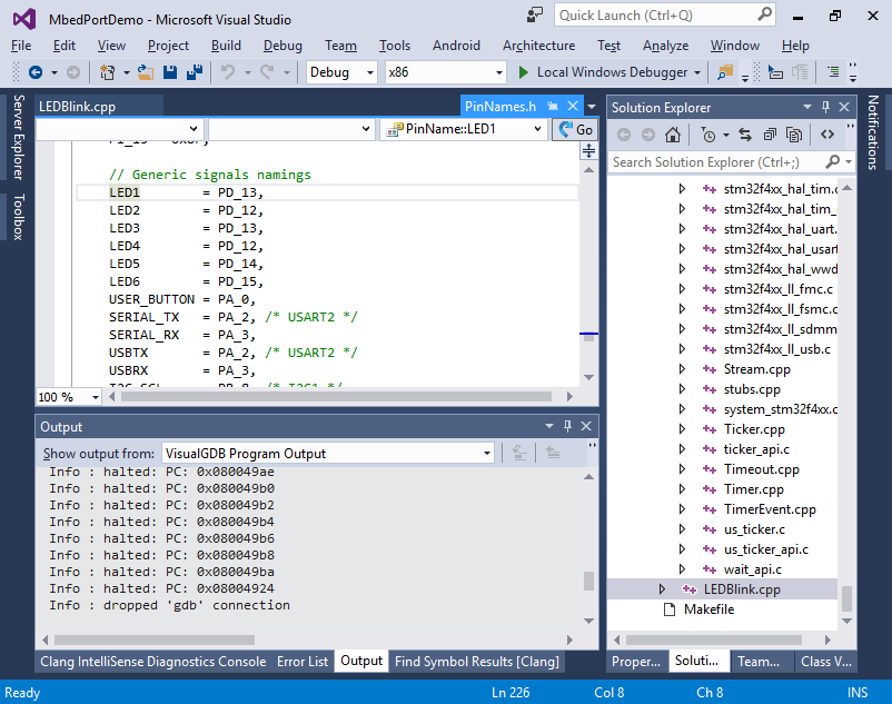
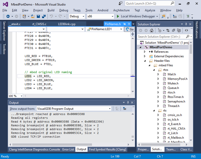
- If you click on the LED1 text in your code and select “Go to definition”, you will see that it’s defined in the PinName enum as an alias for PD_13. You will also see other meaningful names like USER_BUTTON. Those names are defined independently for each supported mbed platform so that the application developers don’t need to look up the pin numbers in the schematic.
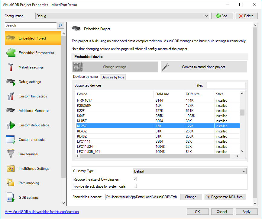
- Now we will switch the project to the KL25Z platform. First, follow this tutorial to ensure that you can program the KL25Z board successfully. Then open VisualGDB Project Properties for the mbed project and switch the device to KL25Z:
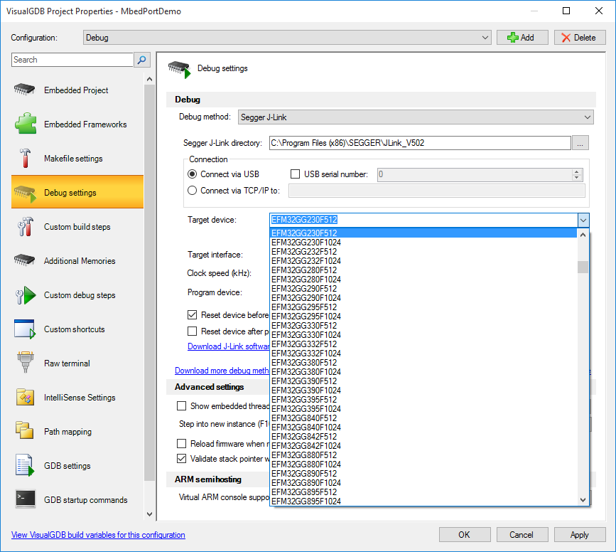
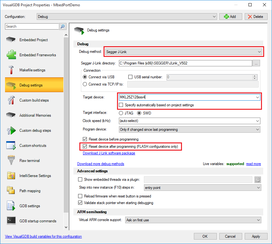
- Then go to the Debug Settings page and switch the debug method to Segger J-Link. Select the device manually (MKL25Z128xxx4) as the KL25Z name is too generic and check the “Reset device after programming” checkbox:
- Try building your project. The compiler will show an error indicating that the r7 register cannot be accessed explicitly:
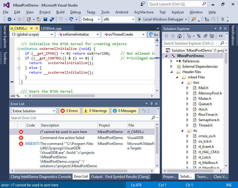
- This happens because the debug build uses r7 to store the frame pointer and the syscall code on Cortex M0 assumes that it is available. Fix this by adding the following line right after the SVC_Call() definition for Cortex M0:
#pragma GCC optimize ("-fomit-frame-pointer")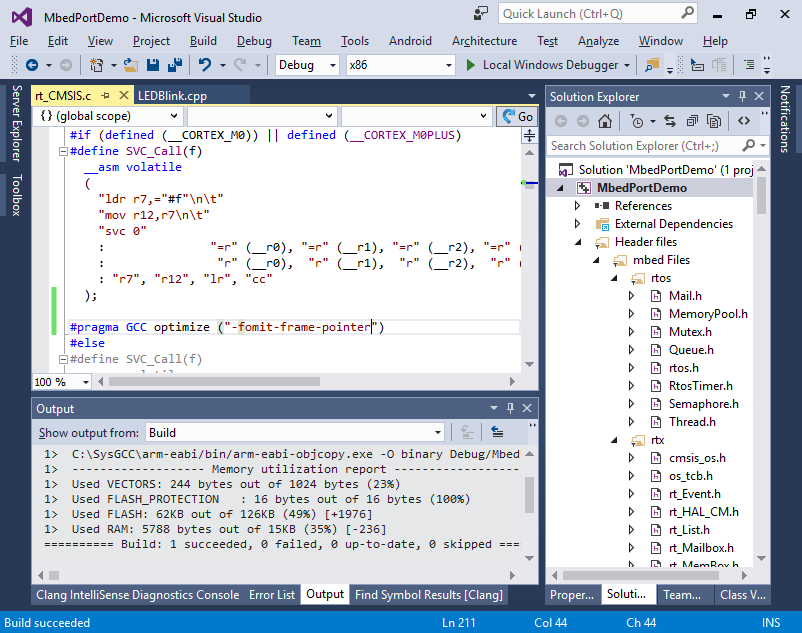
- Build and run your project. Observe how the red and green channels of the RGB LED show the same behavior as the green and yellow LEDs did on STM32F4Discovery:
- If you go to the definition of the LED1 now, you will see that it is defined differently for KL25Z reflecting different board schematic:
 You can repeat the steps shown above to retarget the project to any device supported by mbed as long as you update the debug settings so that VisualGDB can program and debug your board.
 - If you are using one of the boards not directly supported by VisualGDB, you can enable manual setup in the OpenOCD settings and pick the interface and board/target scripts manually from the list, however they may need to be edited before they can work:
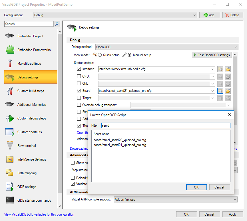 The scripts are located under %LOCALAPPDATA%\VisualGDB\EmbeddedDebugPackages\com.sysprogs.arm.openocd\share\openocd\scripts.
 - If you are using Segger J-Link, the setup will be much easier. Simply pick the device name from the list and the Segger software will configure everything automatically: