Using the ESP8266 RTOS SDK to create multi-threaded firmware
This tutorial shows how to use the ESP8266 RTOS SDK to create multi-threaded applications. We will demonstrate how to create 2 threads that will run in parallel and how to work around known problems related to the RTOS SDK. Before you begin, follow our ESP8266 OpenOCD tutorial to get start with JTAG debugging of your ESP8266.
Warning: this tutorial features an older version of the ESP8266 RTOS SDK. See this tutorial for the new Advanced ESP8266 Project Subsystem supporting RTOS SDK 3.x.
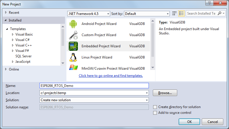
- Start Visual Studio. Select File->New->Project and choose the VisualGDB Embedded Project Wizard:
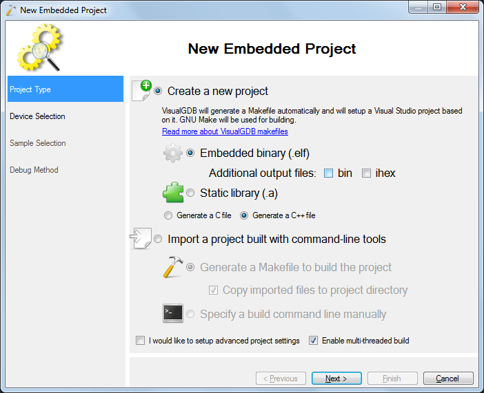
- Proceed with the “Create a new project” setting. You can disable the creation of the “.bin” files as the ESP8266 uses a different binary format that is handled by VisualGDB separately:
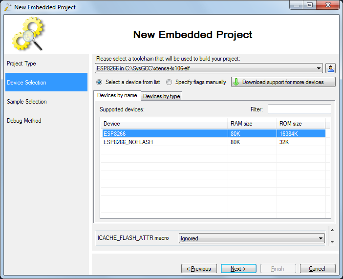
- Select the ESP8266 device from the device list. Note that the RTOS SDK is too large to fit entirely into SRAM, so you will need to use the SPI FLASH:
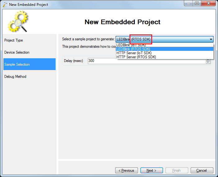
- Select the LEDBlink (RTOS SDK) sample. It will automatically select the FreeRTOS SDK instead of the olderIoT SDK:
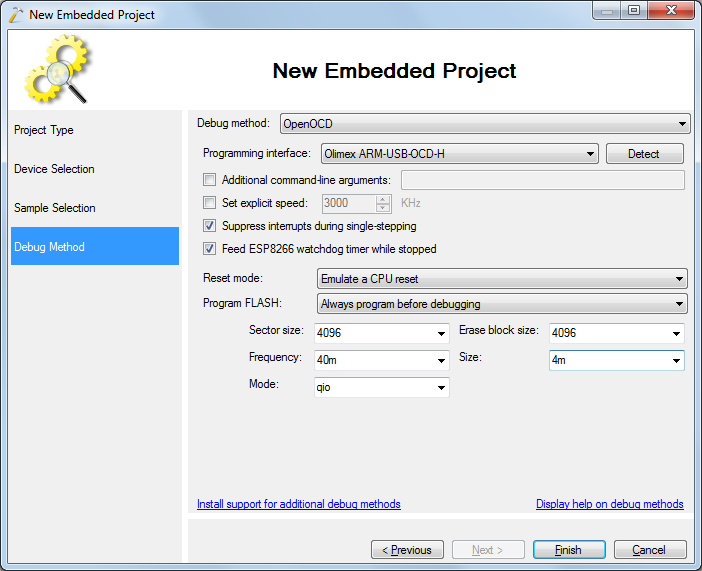
- On the last page of the wizard specify the debug settings that worked for the code in the OpenOCD tutorial:
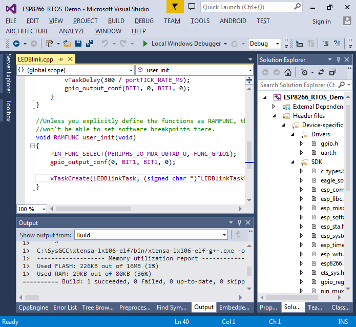
- Once you press “Finish”, VisualGDB will create a project for you. You can build it by pressing Ctrl-Shift-B:
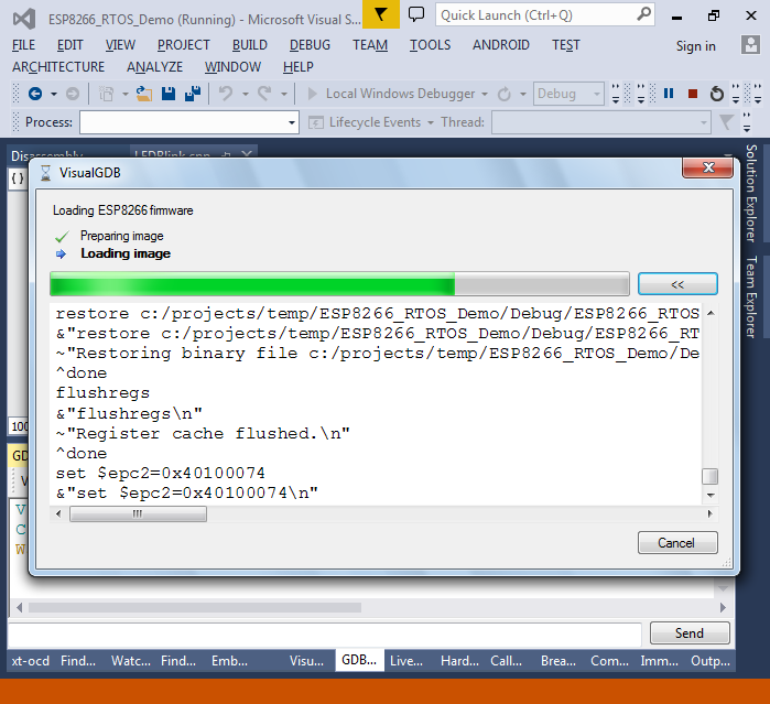
- Hit F5 to program the project into the SPI FLASH and start it:
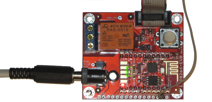
- Observe that the LED on the board is blinking:
- Set a breakpoint in the LEDBlinkTask function and try inspecting the “tick” variable:
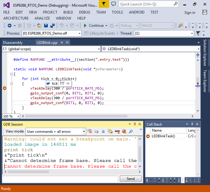 You won’t be able to see the value of the variable because of the limitation of the lx106 debugger, as it can only locate local variables after it has found the function calling the current one.
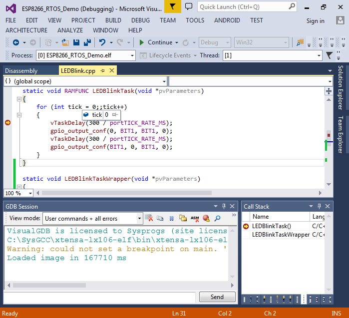
 - To work around the limitation, add a wrapper function calling LEDBlinkTask() and pass it to xTaskCreate() instead of LEDBlinkTask():
static void LEDBlinkTaskWrapper(void *pvParameters)
{
    LEDBlinkTask(pvParameters);
}
- Now you can run our code and actually see the contents of the ‘tick’ variable:
- Note that both LEDBlinkTask() and user_init() are declared with the RAMFUNC modifier. You can use the preprocessor lens to see that it actually means placing the code to the “.entry.text” section:
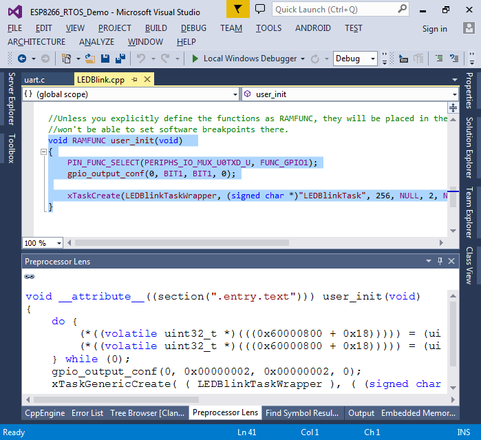
- This is done because the default linker script in the RTOS SDK (eagle.app.v6.ld) places all code into the SPI FLASH and only the code from sections like “.entry.text” ends up in RAM:
  .text : ALIGN(4)
  {
    _stext = .;
    _text_start = ABSOLUTE(.);
    <...>
    *(.entry.text)
    *(.init.literal)
    *(.init)
    *(.literal .text .stub .gnu.warning .gnu.linkonce.literal.* .gnu.linkonce.t.*.literal .gnu.linkonce.t.*)
    *(.fini.literal)
    *(.fini)
    *(.gnu.version)
    _text_end = ABSOLUTE(.);
    _etext = .;
  } >iram1_0_seg :iram1_0_phdr
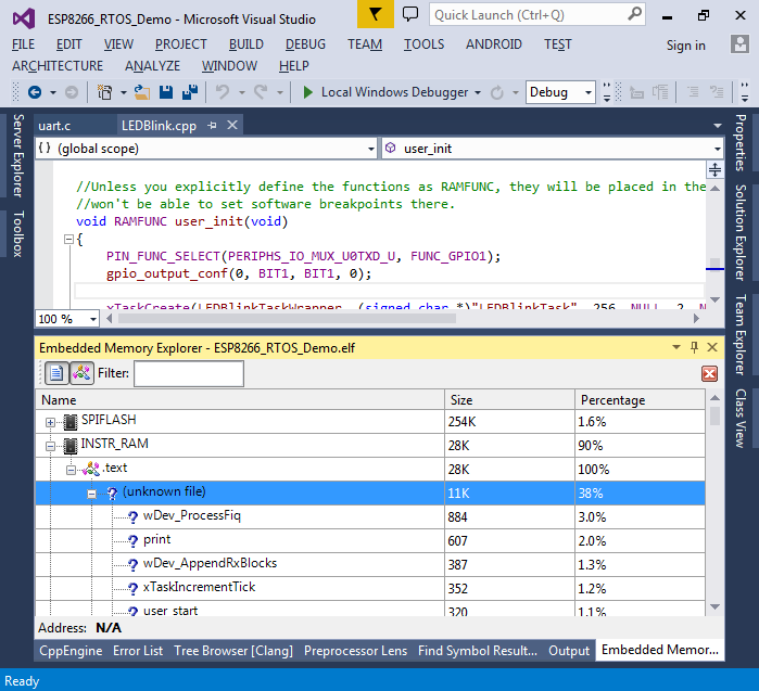
- You can use the Embedded Memory Explorer to see what code goes into the instruction RAM:
- Now we will create another thread that will stop and resume the first thread periodically. Add the following code to your main source file:
xTaskHandle s_BlinkTask;

static void RAMFUNC ControlTask(void *pvParameters)
{
    for (;;)
    {
        vTaskDelay(1000 / portTICK_RATE_MS);
        vTaskSuspend(s_BlinkTask);
        vTaskDelay(1000 / portTICK_RATE_MS);
        vTaskResume(s_BlinkTask);
    }
}
- Update the previous call to xTaskCreate() to save the task handle to s_BlinkTask and create another task for the ControlTask() function:
    xTaskCreate(LEDBlinkTaskWrapper, (signed char *)"LEDBlinkTask", 256, NULL, 2, &s_BlinkTask);
    xTaskCreate(ControlTask, (signed char *)"ControlTask", 256, NULL, 2, NULL);
Build and run your code. Observe how the LED now pauses for a while every 2 seconds.
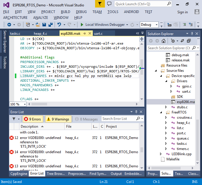
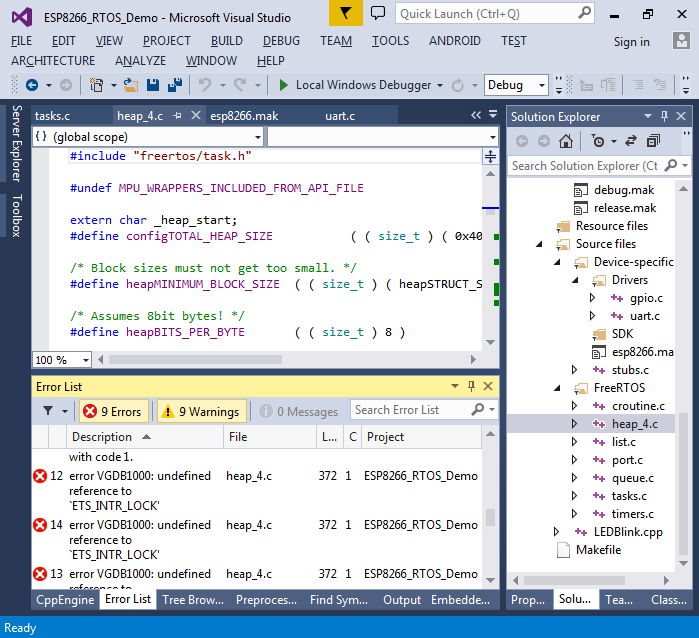
- Functions like vTaskDelay() and xTaskCreate() are provided by FreeRTOS – an open-source real-time operating system that is a part of the ES8266 RTOS SDK. However, the FreeRTOS library that comes with the SDK does not have debug symbols, so you cannot step into the FreeRTOS functions. We will now replace the default FreeRTOS library with the version compiled from the source code with debug symbols. Create a new virtual folder called FreeRTOS in Solution Explorer and import files from (toolchain)\esp8266-bsp\RTOS-SDK\third_party\freertos. However if you try bulding the solution now, you will see compilation errors:
- This happens because the heap_4.c file that comes with the SDK references the undefined ETS_INTR_LOCK() and ETS_INTR_UNLOCK macros. You can define them as follows in the heap_4.c file:
#define ETS_INTR_LOCK taskENTER_CRITICAL
#define ETS_INTR_UNLOCK taskEXIT_CRITICAL
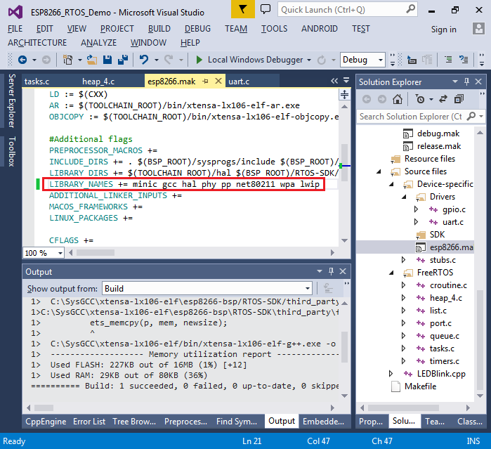
- Finally remove the reference to the freertos library in the esp8266.mak file:
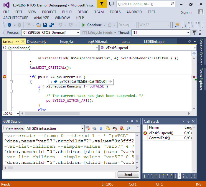
- Now you can set breakpoints inside the FreeRTOS functions and evaluate the variables:
 As the FreeRTOS functions will be placed into SPI FLASH, you cannot set software breakpoints inside them. VisualGDB will automatically convert the breakpoints you set into hardware breakpoints, however as the ESP8266 chip as only one hardware breakpoint, you cannot have more than one breakpoint in code outside SRAM. Furthermore, while the hardware breakpoint is used, stepping won’t work as the stepping logic requires that breakpoint. You can work around this by placing some of the RTOS functions into SRAM by using the method we used earlier to place user_init() into SRAM.
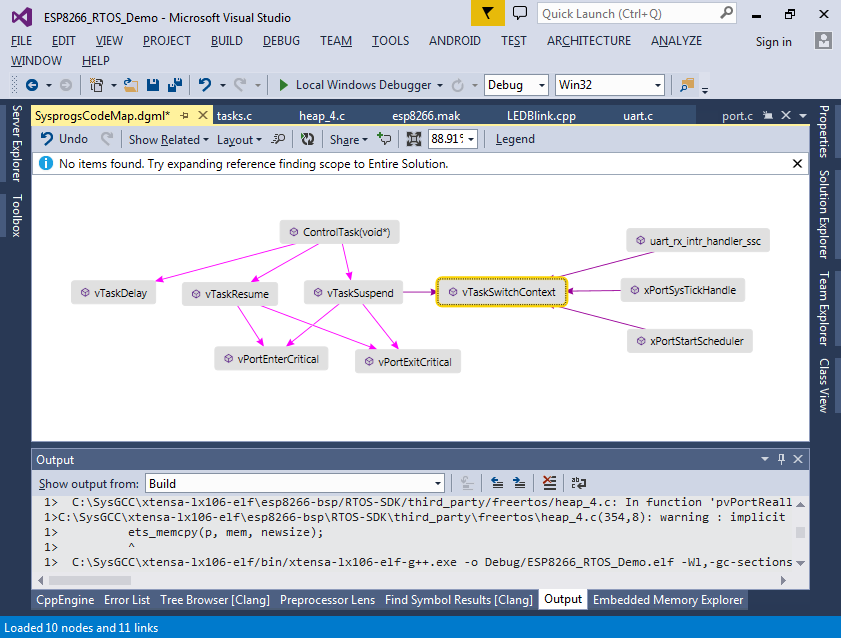
 - You can also use Code Map to quickly see the relations between various FreeRTOS functions: