Using the STM32 UART interface with HAL
This tutorial shows how to use the STM32 UART interface in different modes using the HAL libraries. We will show how to use direct mode, interrupt-based mode and DMA-controlled mode and will use a logic analyzer to compare the precise timings of various events.
Before you begin, install VisualGDB 5.2 or later.
- Start Visual Studio and open VisualGDB Embedded Project Wizard:

- Select “Create a new project with MSBuild -> Embedded Binary”:

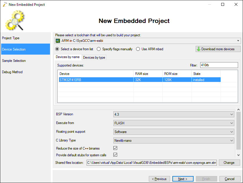
- On the next page select your STM32 device. We will use the Nucleo-F410RB board that has the STM32F410RB chip:
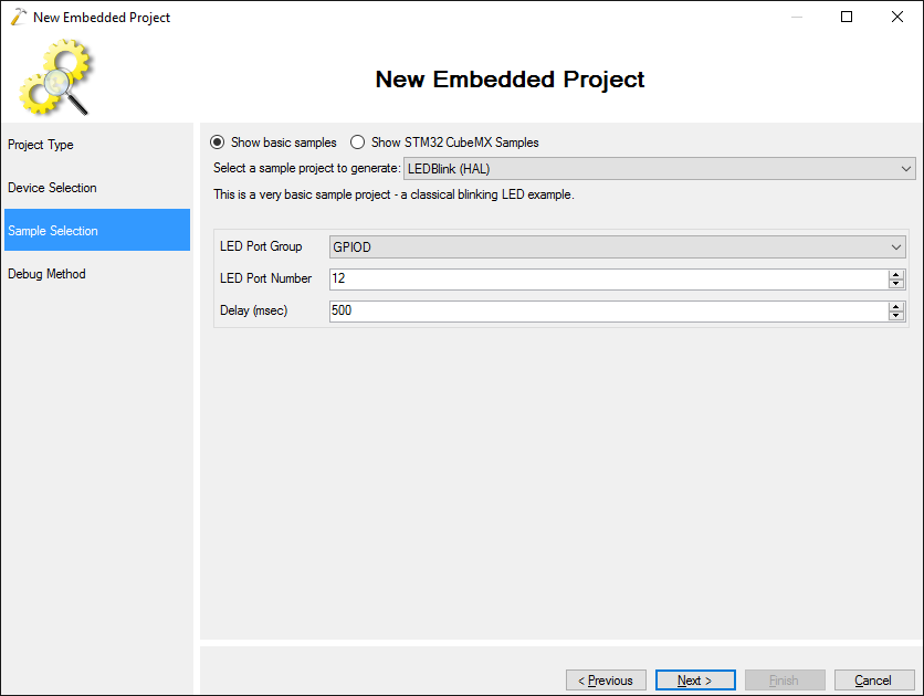
- Proceed with the default “LEDBlink (HAL)” sample:
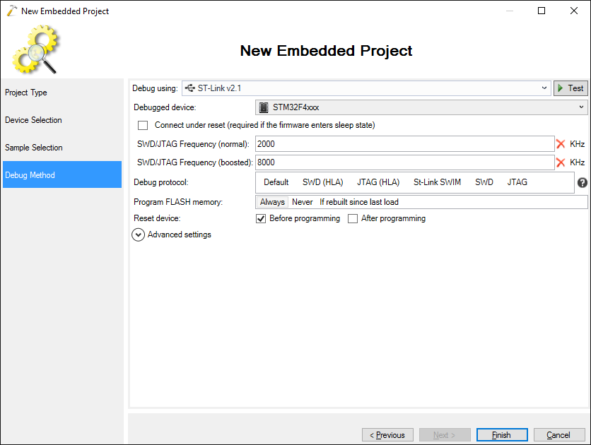
- Connect your board to USB and let VisualGDB automatically recognize it and configure debug settings:
- Press “Finish” to create the project. We will begin with a simple program that will read bytes via UART and echo them back in groups of 4. This requires four steps:
- Enabling the clocks for the UART and GPIO peripherals.
- Configuring the GPIO pins corresponding to UART to actually act as UART pins (as opposed to manually controlled GPIO) pins.
- Initializing the UART module by specifying the operating parameters.
- Actually reading and writing the data.
Replace the code in your main source file with the following:
#include <stm32f4xx_hal.h>
#include <stm32_hal_legacy.h>

#ifdef __cplusplus
extern "C"
#endif
void SysTick_Handler(void)
{
    HAL_IncTick();
    HAL_SYSTICK_IRQHandler();
}

static UART_HandleTypeDef s_UARTHandle = UART_HandleTypeDef();

int main(void)
{
    HAL_Init();

    __USART2_CLK_ENABLE();
    __GPIOA_CLK_ENABLE();

    GPIO_InitTypeDef GPIO_InitStructure;

    GPIO_InitStructure.Pin = GPIO_PIN_2;
    GPIO_InitStructure.Mode = GPIO_MODE_AF_PP;
    GPIO_InitStructure.Alternate = GPIO_AF7_USART2;
    GPIO_InitStructure.Speed = GPIO_SPEED_HIGH;
    GPIO_InitStructure.Pull = GPIO_NOPULL;
    HAL_GPIO_Init(GPIOA, &GPIO_InitStructure);

    GPIO_InitStructure.Pin = GPIO_PIN_3;
    GPIO_InitStructure.Mode = GPIO_MODE_AF_OD;
    HAL_GPIO_Init(GPIOA, &GPIO_InitStructure);

    s_UARTHandle.Instance        = USART2;
    s_UARTHandle.Init.BaudRate   = 115200;
    s_UARTHandle.Init.WordLength = UART_WORDLENGTH_8B;
    s_UARTHandle.Init.StopBits   = UART_STOPBITS_1;
    s_UARTHandle.Init.Parity     = UART_PARITY_NONE;
    s_UARTHandle.Init.HwFlowCtl  = UART_HWCONTROL_NONE;
    s_UARTHandle.Init.Mode       = UART_MODE_TX_RX;

    if (HAL_UART_Init(&s_UARTHandle) != HAL_OK)
        asm("bkpt 255");

    for (;;)
    {
        uint8_t buffer[4];
        HAL_UART_Receive(&s_UARTHandle, buffer, sizeof(buffer), HAL_MAX_DELAY);
        HAL_UART_Transmit(&s_UARTHandle, buffer, sizeof(buffer), HAL_MAX_DELAY);
    }
}
- We are using UART2 and pins PA2 and PA3 as the Nucleo-F410RB board has them connected to the on-board ST-Link UART interface, so we can use a terminal to interact with the board. You can find the GPIO pin numbers and the alternate function numbers corresponding to the UART interface on your device by searching the datasheet for the Alternate Function Mapping section:
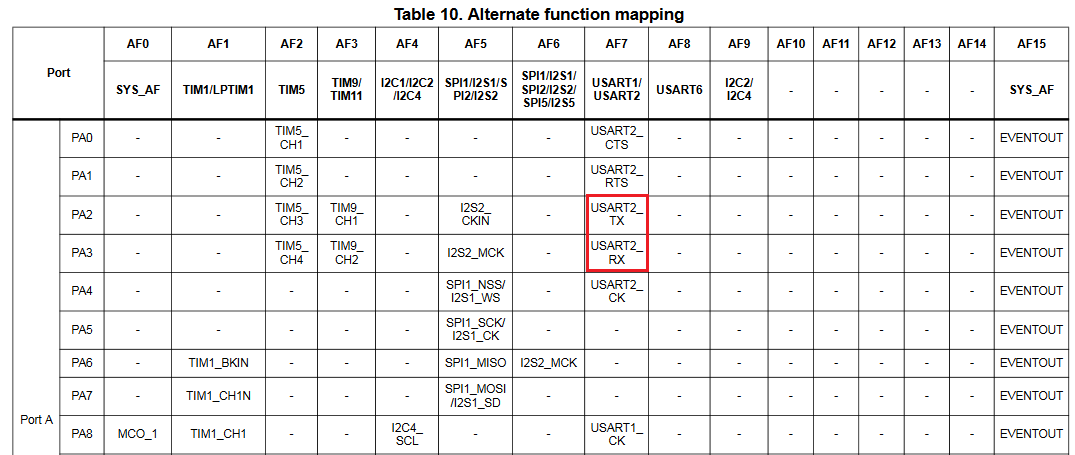 For STM32F410RB connecting UART2 to pins PA2 and PA3 requires enabling alternate function #7.
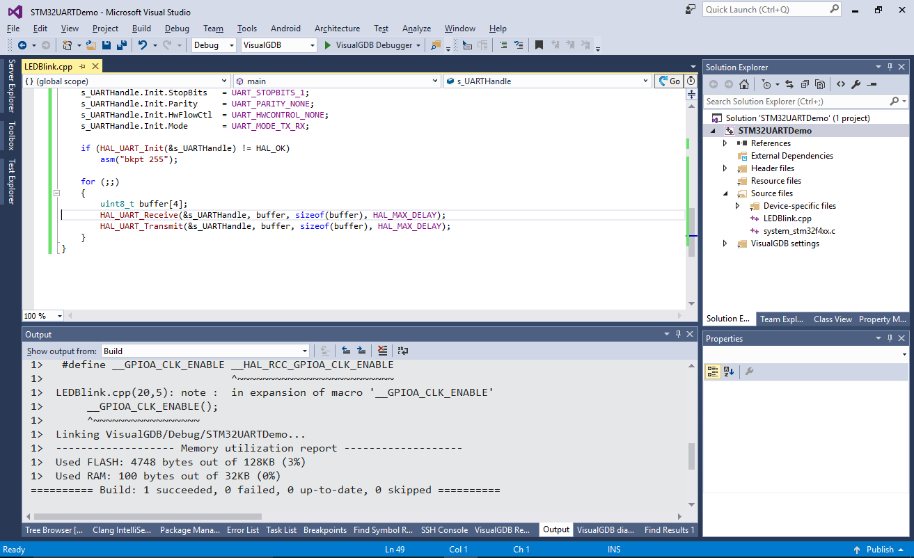
 - Build the code by pressing Ctrl-Shift-B:
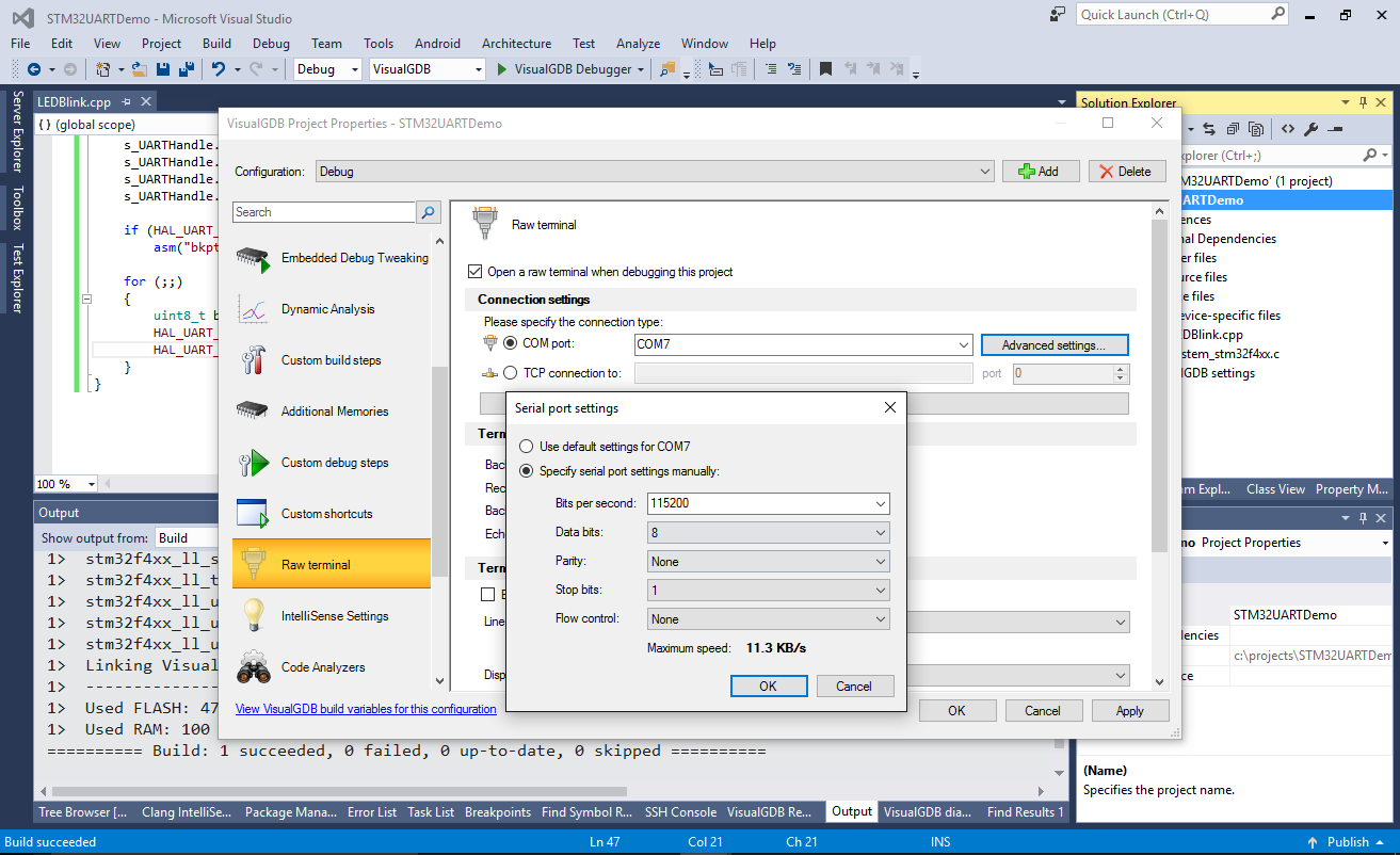
- You can use a terminal program to talk to your STM32 board over the UART interface. If you are using VisualGDB Custom Edition, simply enable the Raw Terminal in VisualGDB Project Properties and it will show a terminal window inside the Visual Studio window:
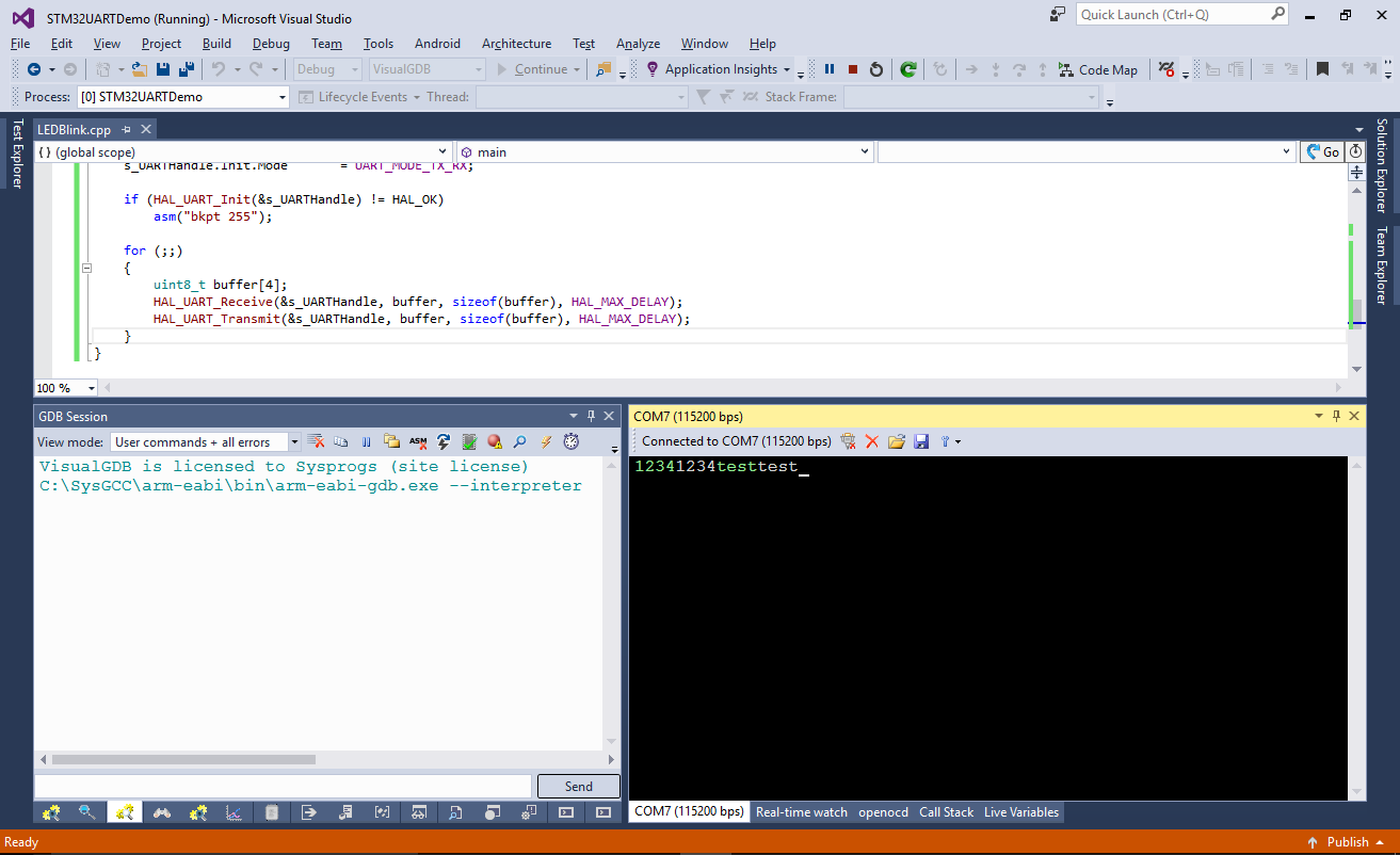
- Press F5 to start debugging. Try typing some text in the terminal window and see how after every 4 characters the program echoes them back:
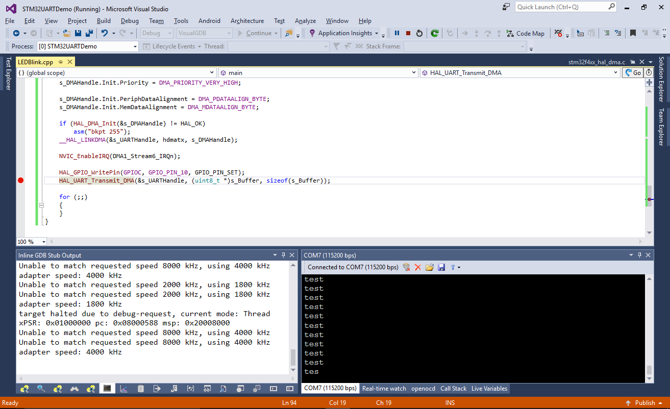
- Now we will explore the UART timings using a logic analyzer. First of all, modify your code to continuously output “test\r\n” and use GPIOC10 to signal the lifetime of the HAL_UART_Transmit() function:
    __GPIOC_CLK_ENABLE();
    GPIO_InitStructure.Pin = GPIO_PIN_10 | GPIO_PIN_11 | GPIO_PIN_12;
    GPIO_InitStructure.Mode = GPIO_MODE_OUTPUT_PP;
    HAL_GPIO_Init(GPIOC, &GPIO_InitStructure);

    for (;;)
    {
        char buffer[] = "test\r\n";
        HAL_GPIO_WritePin(GPIOC, GPIO_PIN_10, GPIO_PIN_SET);
        HAL_UART_Transmit(&s_UARTHandle, buffer, sizeof(buffer), HAL_MAX_DELAY);
        HAL_GPIO_WritePin(GPIOC, GPIO_PIN_10, GPIO_PIN_RESET);
        HAL_Delay(2);
    }
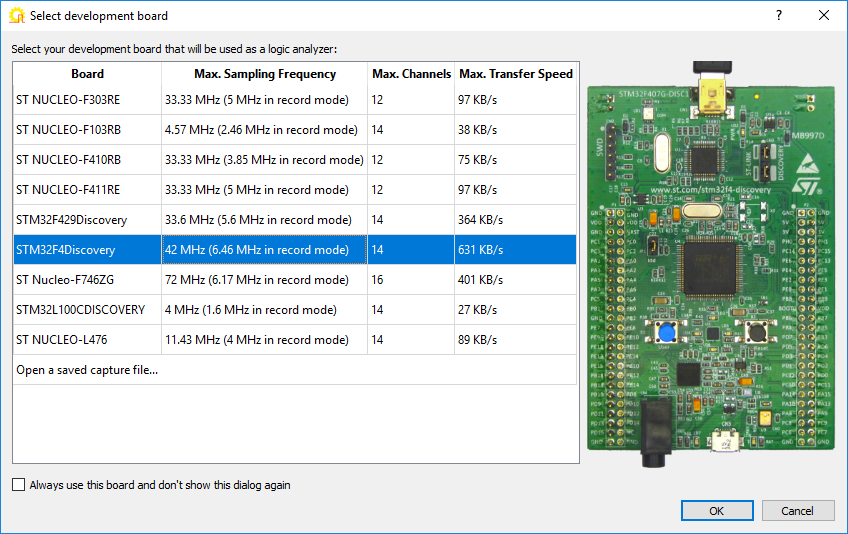
- We will use Analyzer2Go to turn another STM32 board into a full-featured logic analyzer. Connect your second board to your computer, start Analyzer2Go and select the board type:
- Connect the following signals between the boards:
Signal Board running firmware Board running logic analyzer Ground GND GND UART output TX Any of the supported inputs HAL_UART_Transmit() lifetime indicator PC10 Any of the supported inputs 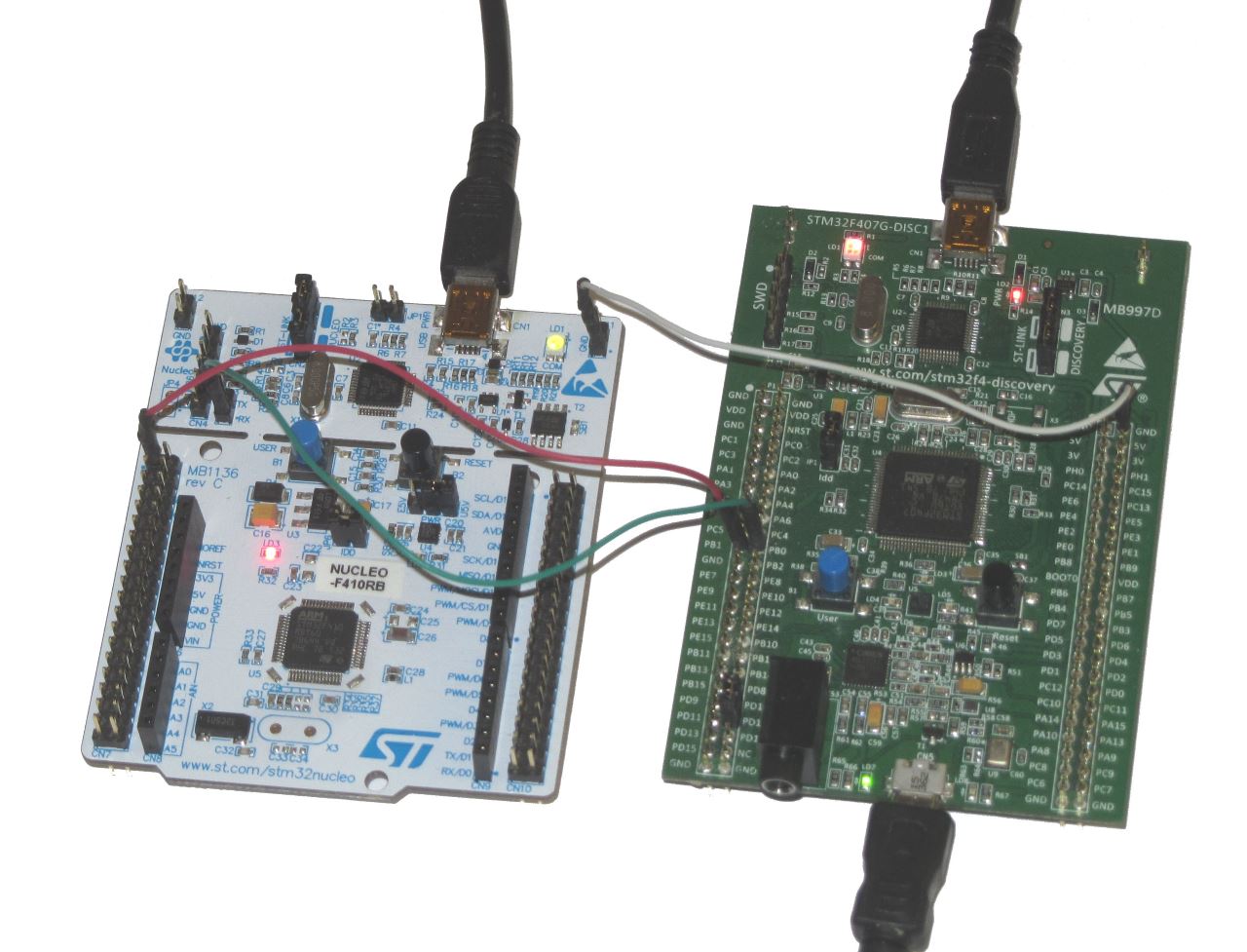
- Enable the connected signals in Analyzer2go to begin watching them. See how the HAL_UART_Transmit() function (red) is active during the entire transmission (blue):
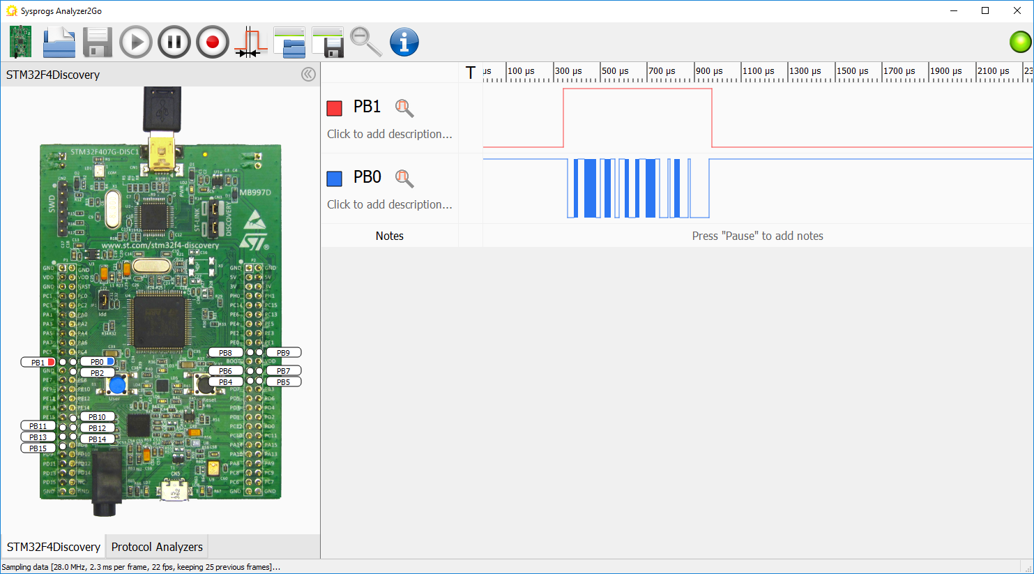
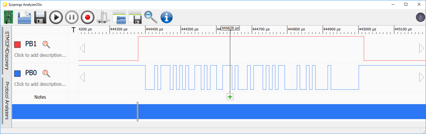
- Press the “Record” button to record several packets in a row. Then stop recording and zoom into one of them:
- In order to automatically decode the UART bytes, open the Protocol Analyzers tab, drag/drop the UART analyzer and connect it to the corresponding signal:
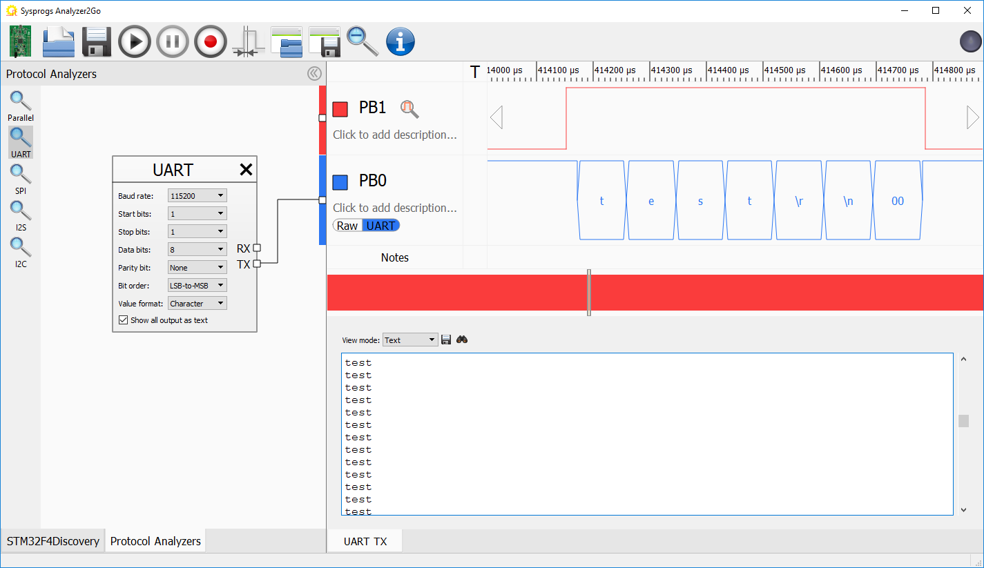
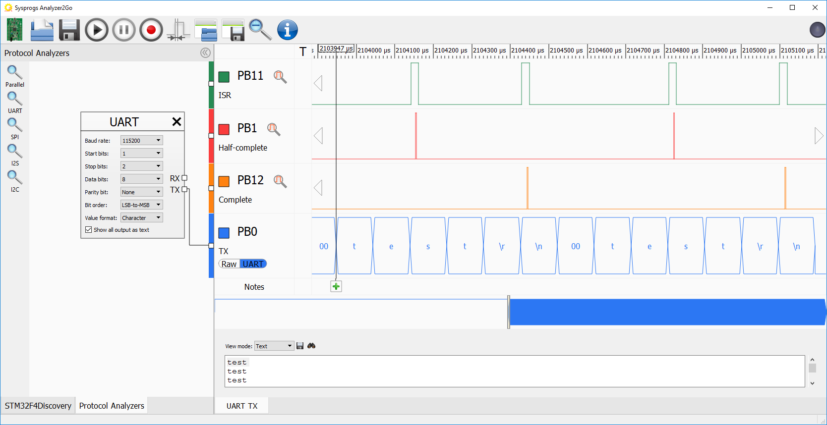
- You can analyze the raw encoding of the UART signals by selecting the decoded characters and creating notes for some of them:
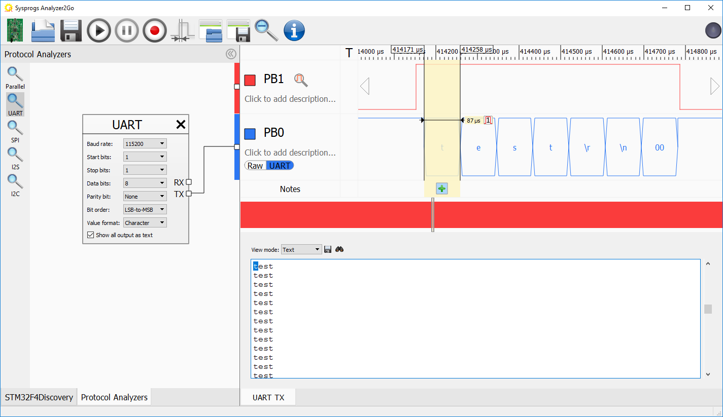
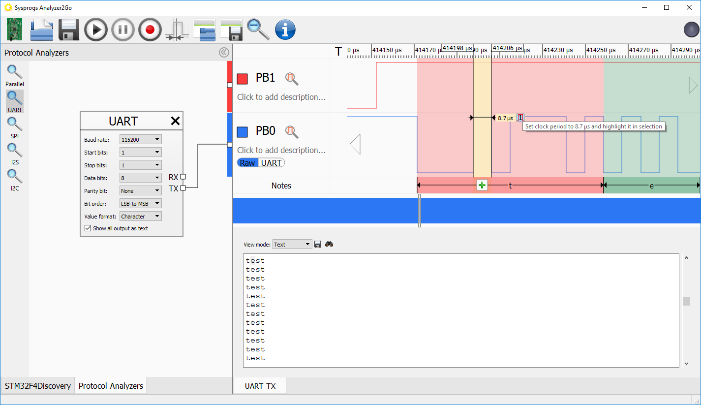
- Then switch to the “Raw” view to see the signal shape. You can click the “set clock period” button to highlight individual zeroes and ones:
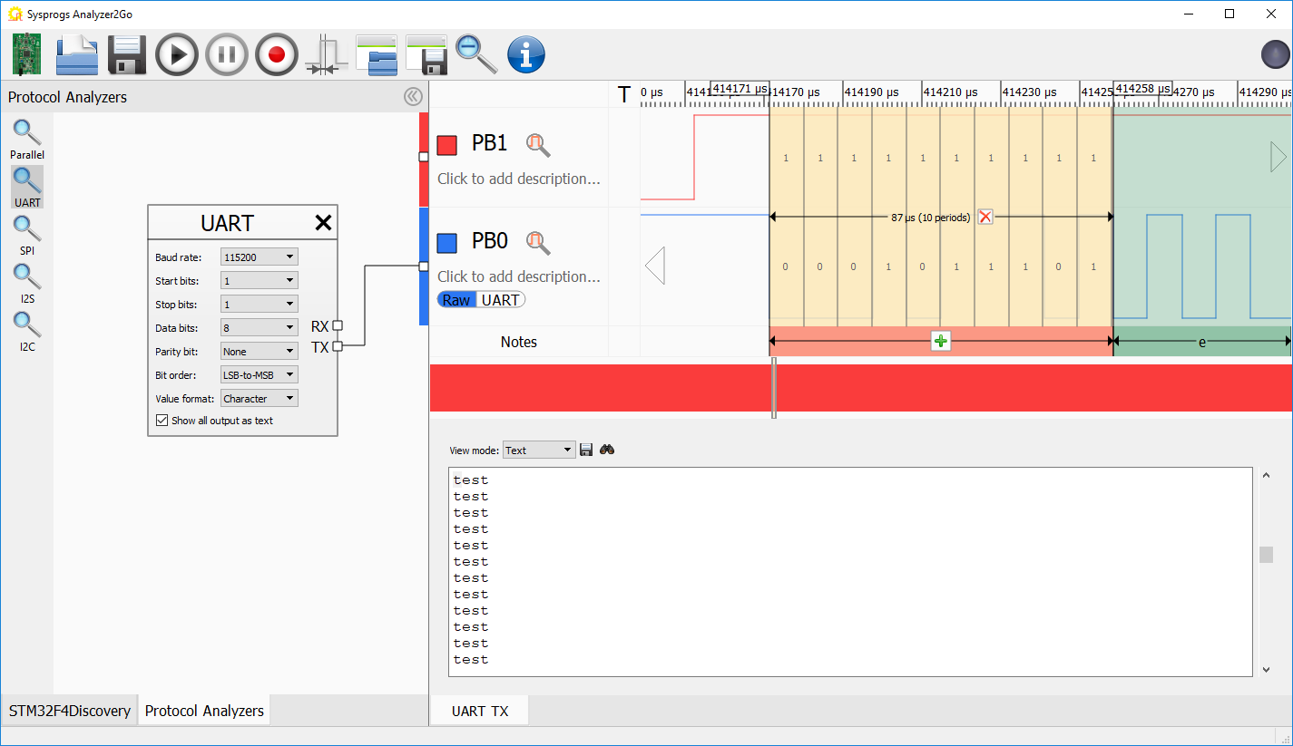
- The ‘t’ character was encoded as 0 0010 1110 1, which corresponds to a start bit (0) followed by a value of 0x74 (ASCII code for ‘t’) followed by a stop bit (1):
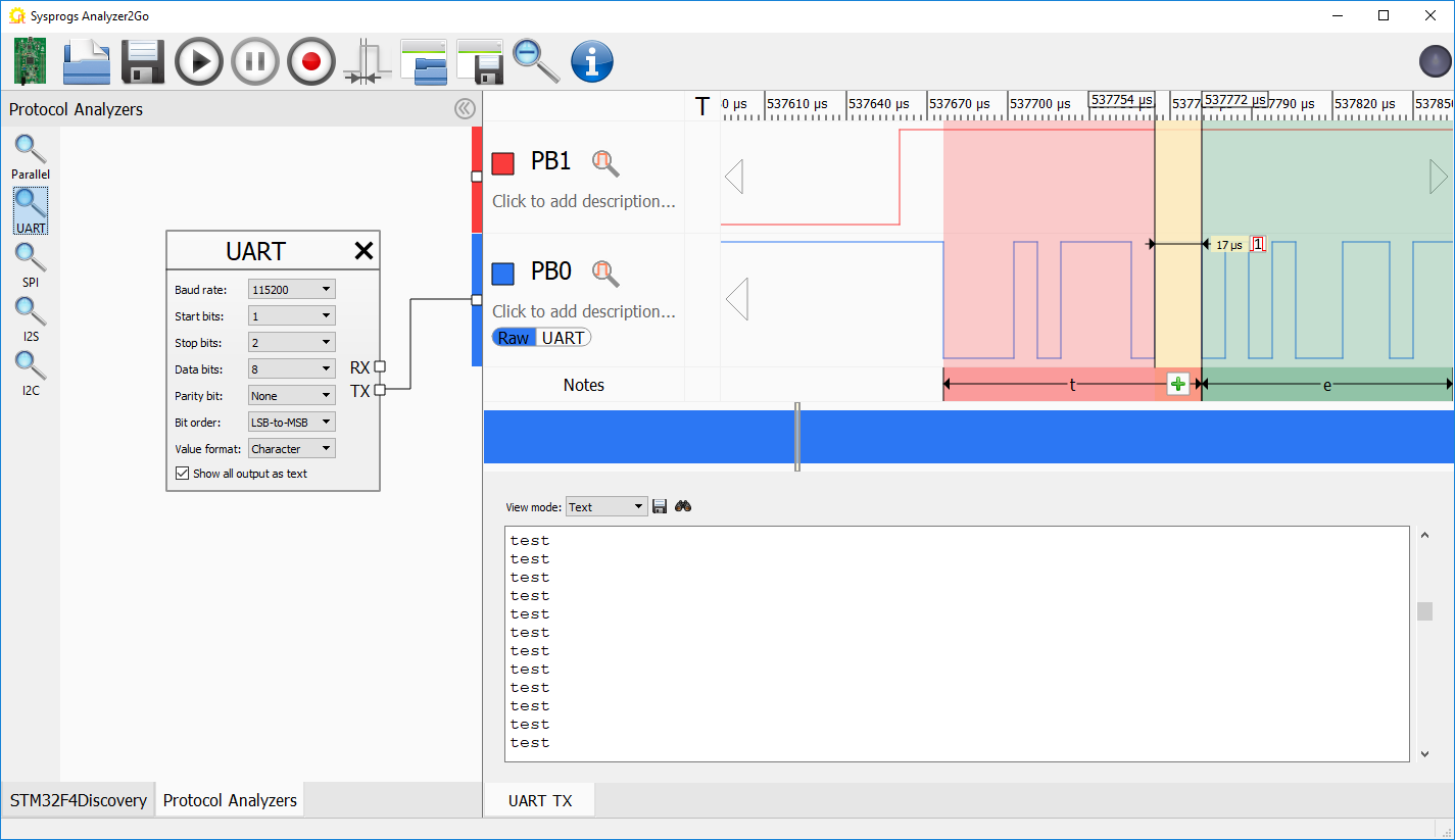
- Try changing the stop bit amount to 2:
s_UARTHandle.Init.StopBits = UART_STOPBITS_2;
See how the stop bit is now twice longer:
- Although calling HAL_UART_Transmit() for every transmission is simple, it has one major disadvanrage. While the transmission is active, the program cannot do anything else and has to wait for it to complete. We will now use the interrupt-based transmission to free up some of the CPU cycles. Replace the code in your main source file with this:
#include <stm32f4xx_hal.h>
#include <stm32_hal_legacy.h>

#ifdef __cplusplus
extern "C"
#endif
void SysTick_Handler(void)
{
    HAL_IncTick();
    HAL_SYSTICK_IRQHandler();
}

static UART_HandleTypeDef s_UARTHandle = UART_HandleTypeDef();

extern "C" void USART2_IRQHandler()
{
    HAL_GPIO_WritePin(GPIOC, GPIO_PIN_12, GPIO_PIN_SET);
    HAL_UART_IRQHandler(&s_UARTHandle);
    HAL_GPIO_WritePin(GPIOC, GPIO_PIN_12, GPIO_PIN_RESET);
}

void HAL_UART_TxCpltCallback(UART_HandleTypeDef *huart)
{
    HAL_GPIO_WritePin(GPIOC, GPIO_PIN_11, GPIO_PIN_RESET);
}

int main(void)
{
    HAL_Init();

    // <Initialize UART and GPIO as before>

    __GPIOC_CLK_ENABLE();
    GPIO_InitStructure.Pin = GPIO_PIN_10 | GPIO_PIN_11 | GPIO_PIN_12;
    GPIO_InitStructure.Mode = GPIO_MODE_OUTPUT_PP;
    HAL_GPIO_Init(GPIOC, &GPIO_InitStructure);

    NVIC_EnableIRQ(USART2_IRQn);

    for (;;)
    {
        char buffer[] = "test\r\n";
        HAL_GPIO_WritePin(GPIOC, GPIO_PIN_10 | GPIO_PIN_11, GPIO_PIN_SET);
        HAL_GPIO_WritePin(GPIOC, GPIO_PIN_12, GPIO_PIN_RESET);
        HAL_UART_Transmit_IT(&s_UARTHandle, (uint8_t *)buffer, sizeof(buffer));
        HAL_GPIO_WritePin(GPIOC, GPIO_PIN_10, GPIO_PIN_RESET);
        HAL_Delay(2);
    }
}
Don’t forget to copy the previous initialization code for UART and GPIO.
- Set a breakpoint in HAL_UART_TxCpltCallback(), start debugging and wait for it to trigger. Then check the call stack:
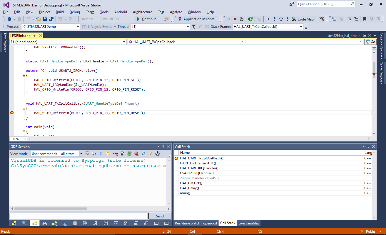 You can see how the UART interrupt got invoked when the main() function was already running HAL_Delay(). The USART2_IRQHandler() handler called the HAL_UART_IRQHandler() and the HAL_UART_IRQHandler() in turn called the HAL_UART_TxCpltCallback() once it determined that the last byte got transmitted.
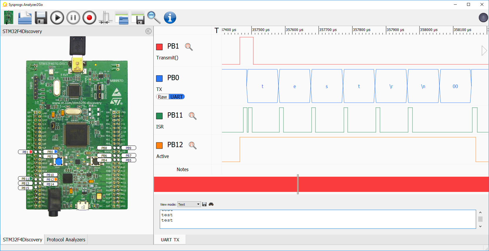
 - Remove the breakpoint and restart the program. Then add the C11 and C12 signals to Analyzer2Go and make another recording. Note how the HAL_UART_Transmit_IT() function returns immediately (red) and the interrupt handler (green) is called after each byte is queued for transmission. Finally, the HAL_UART_TxCpltCallback() (orange signal switching to 0) is called once the last byte was physically sent:
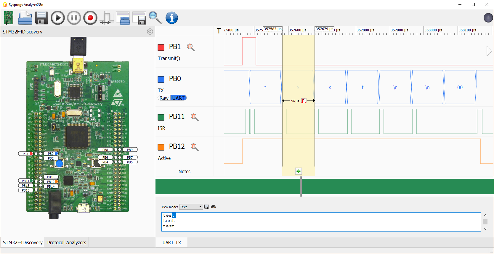
- Most of the time during the transmission the CPU will be able to run code unrelated to the transmission. It will only be interrupted by occasional UART interrupts. You can measure the overhead of the UART interrupts by comparing the byte transmission period to the width of the ‘ISR’ pulse. For STM32F410RB the overhead is 12 out of 96 microseconds (12.5%) regardless of the buffer size:
- In order to reduce the interrupt-related overhead, we will show switch UART to use DMA (direct memory access). In this mode the DMA controller will automatically feed the entire buffer to the UART byte-by-byte and only raise an interrupt once the entire buffer is sent. Add the following static variable:
static DMA_HandleTypeDef s_DMAHandle = DMA_HandleTypeDef();
Then replace the code below the code initializing GPIOC with the following:
    __DMA1_CLK_ENABLE();
    s_DMAHandle.Instance = DMA1_Stream6;
    s_DMAHandle.Init.Channel = DMA_CHANNEL_4;

    s_DMAHandle.Init.Direction = DMA_MEMORY_TO_PERIPH;
    s_DMAHandle.Init.PeriphInc = DMA_PINC_DISABLE;
    s_DMAHandle.Init.MemInc = DMA_MINC_ENABLE;
    s_DMAHandle.Init.Mode = DMA_CIRCULAR;

    s_DMAHandle.Init.Priority = DMA_PRIORITY_VERY_HIGH;

    s_DMAHandle.Init.PeriphDataAlignment = DMA_PDATAALIGN_BYTE;
    s_DMAHandle.Init.MemDataAlignment = DMA_PDATAALIGN_BYTE;

    if (HAL_DMA_Init(&s_DMAHandle) != HAL_OK)
        asm("bkpt 255");

    __HAL_LINKDMA(&s_UARTHandle, hdmatx, s_DMAHandle);
    NVIC_EnableIRQ(DMA1_Stream6_IRQn);

    HAL_GPIO_WritePin(GPIOC, GPIO_PIN_10, GPIO_PIN_SET);
    HAL_UART_Transmit_DMA(&s_UARTHandle, (uint8_t *)s_Buffer, sizeof(s_Buffer));

    for (;;)
    {
    }
Remove the UART interrupt handler and add the DMA interrupt handler and 2 UART callbacks:
extern "C" void DMA1_Stream6_IRQHandler()
{
    HAL_GPIO_WritePin(GPIOC, GPIO_PIN_12, GPIO_PIN_SET);
    HAL_DMA_IRQHandler(&s_DMAHandle);
    HAL_GPIO_WritePin(GPIOC, GPIO_PIN_12, GPIO_PIN_RESET);
}

void HAL_UART_TxCpltCallback(UART_HandleTypeDef *huart)
{
    HAL_GPIO_WritePin(GPIOC, GPIO_PIN_10, GPIO_PIN_SET);
    HAL_GPIO_WritePin(GPIOC, GPIO_PIN_10, GPIO_PIN_RESET);
}

void HAL_UART_TxHalfCpltCallback(UART_HandleTypeDef *huart)
{
    HAL_GPIO_WritePin(GPIOC, GPIO_PIN_11, GPIO_PIN_SET);
    HAL_GPIO_WritePin(GPIOC, GPIO_PIN_11, GPIO_PIN_RESET);
}
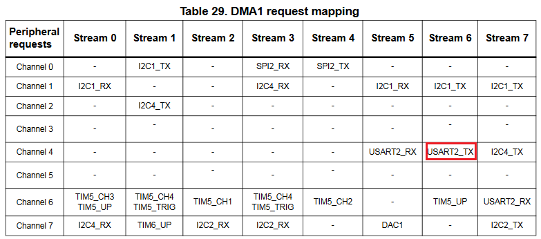
Note that different devices have different DMA channel and stream numbers assigned to UART. Use the DMA Request Mapping table in your device’s reference manual (not datasheet) to get the correct numbers:
- Start the program and ensure you still can see the stream of ‘test’ messages:
- Go back to Analyzer2Go and and check the timing. See how now the DMA interrupt is only called twice per the entire transmission (once for each half of the buffer):
 If you measure the interrupt overhead now you should get 41 microseconds out of 670 (for the entire packet) or ~6%. The DMA interrupt overhead also doesn’t scale up when you increase buffer size, so sending 70 bytes in a packet instead of 7 would reduce the overhead to 0.6%.
 - Having a separate callback for each half of the buffer allows implementing double-buffering. While the DMA is transferring the first half of the buffer, you program could fill the second part with the next frame and vice versa. The same technique would also work for other DMA-capable peripherals, such as SPI (see the SPI tutorial for more details).