Creating a basic Wireless App for CC3200
This tutorial shows how to program the CC3200 microcontroller to create a WiFi access point that will allow connected users to control a LED from their browser. You will need:
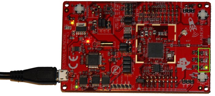
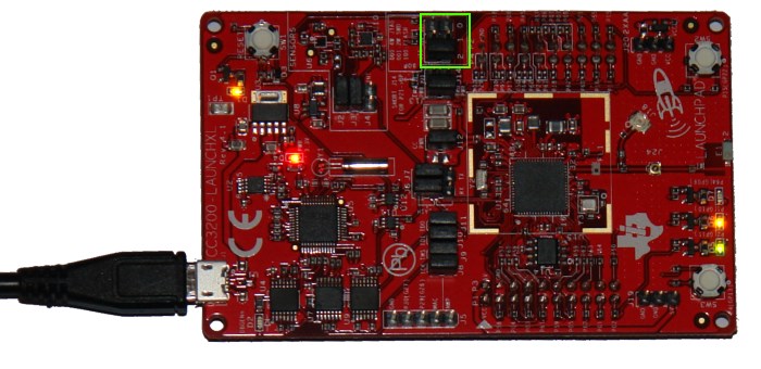
- The CC3200 LaunchPad board from TI
- Visual Studio (including the free Community Edition)
- VisualGDB 4.3
We will start with creating a basic ‘Blinking LED’ firmware, use it to check the connection with the device and then proceed with a more complex HTTP-based LED control demo.
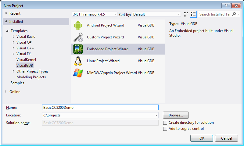
- Create a new VisualGDB Embedded project with Visual Studio:
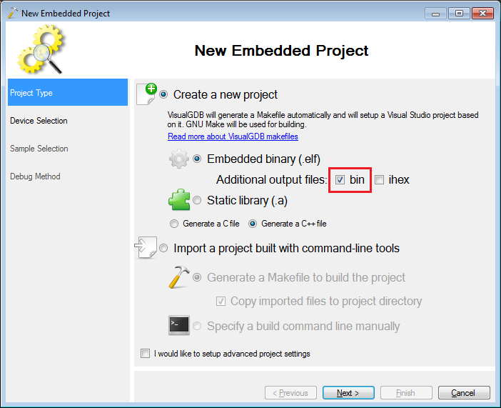
- Ensure that the first page of the wizard enables generation of a .bin file:
- On the next page select the ARM toolchain (if you don’t have it, VisualGDB will download it automatically), then click “Download support for more devices” and install the CC3200 package. The CC3200 chip comes in 2 variations: with 256 and 192 KBytes of SRAM (16KB are reserved for the bootloader). Select the chip that is installed on your Launchpad:
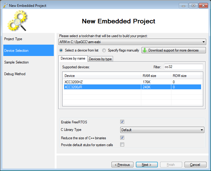 Warning! Older revisions of Launchpad come with the smaller XC3200HZ chip. If you are not sure which chip you have, select the smaller one and once you get it to work, change it to the bigger one.
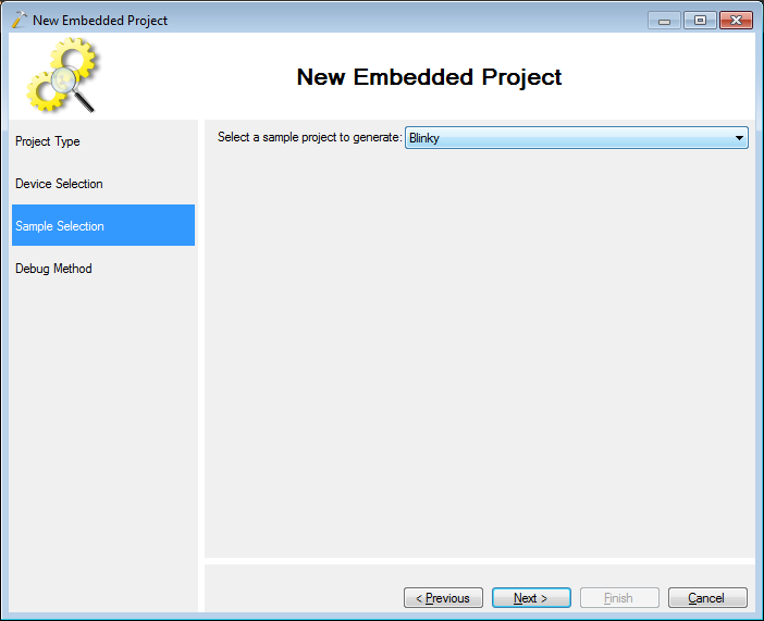
 - On the next page select the Blinky sample:
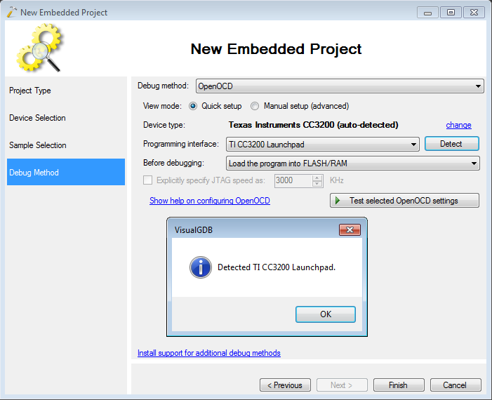
- On the last page select OpenOCD as the debugging method. Connect your Launchpad via USB and press “Detect”. VisualGDB will detect it and select it automatically:
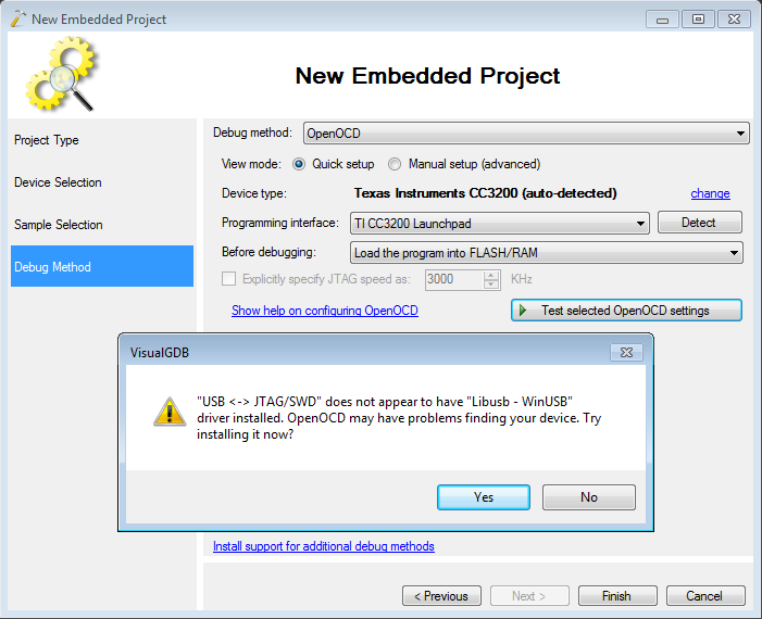
- Press “Test selected OpenOCD settings” to check the connection to the board. Allow VisualGDB to install the Libusb driver for the debug interface (the TI SDK installs the original FT2232 driver that has been deprecated by OpenOCD):
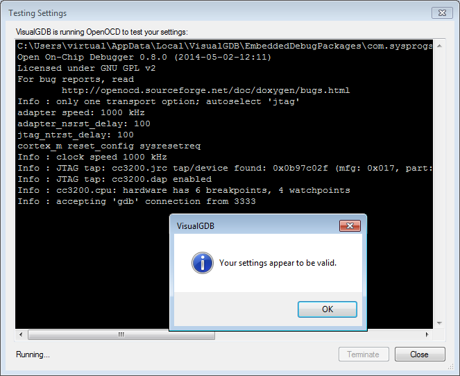
- Ensure that OpenOCD test succeeds:
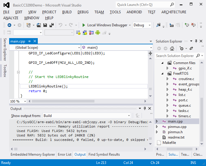
- Press “Finish” to generate the project. Then build it:
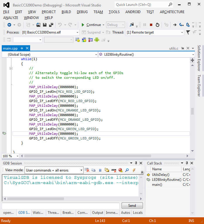
- Start the project by pressing F5. The LEDs on the board should start blinking:
- Select “Break All” in the Debug menu in Visual Studio. Ensure that you see the source code correctly:
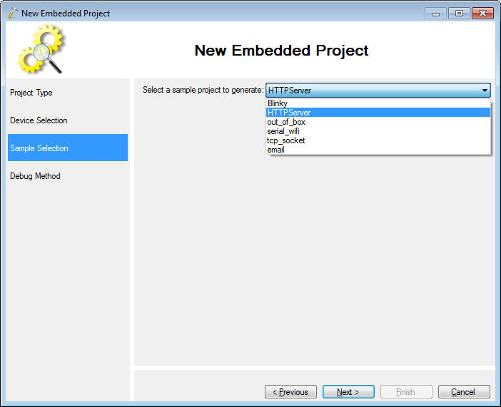
- Now that the basic project is working, use the VisualGDB Project Wizard to create another project based on the HTTPServer sample:
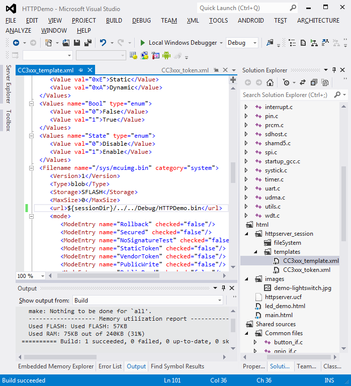
- Before we can debug the HTTP Server, we need to upload the HTML files on the SPI FLASH on the board. The list of the uploaded files is stored in the CC3xxx_templates.xml file. Modify it to reference the debug version of your binary and build the project:
- Now we need to program the files into the serial FLASH. Set a jumper on row 2 (bottommost) of J15 and reset the board:
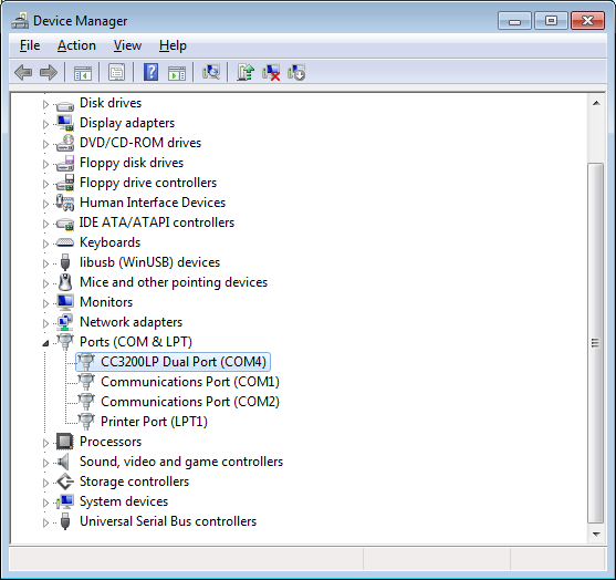
- Make a note of the CCC3200 LaunchPad’s COM port number in the device manager. If it is not shown, install the drivers included in TI CC3200 SDK. If installing the drivers overrides the LibUSB driver we installed earlier, open debug properties and re-test OpenOCD connection to repair the driver:
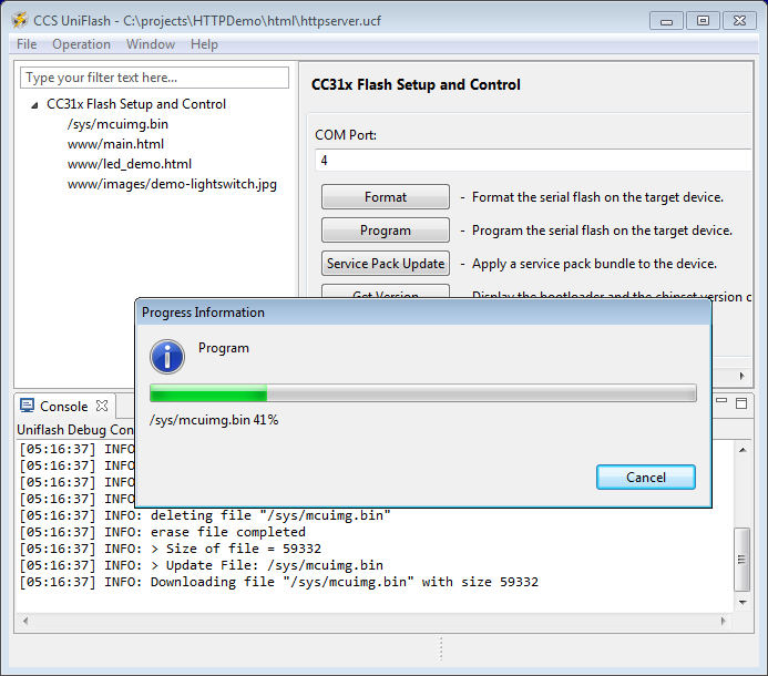
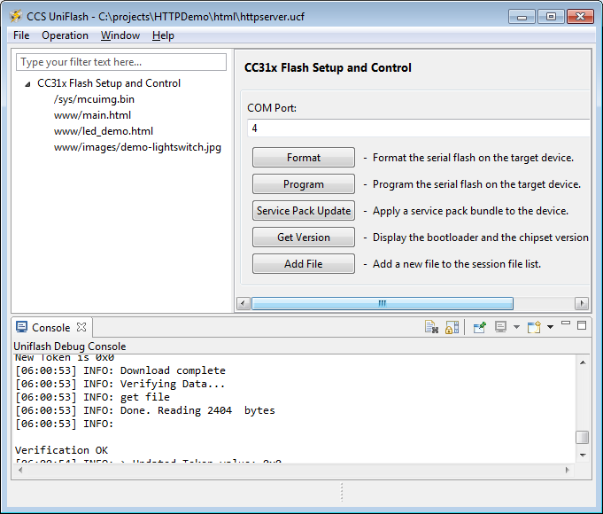
- Download, install and launch the TI UniFlash tool. Open the <project dir>\HTML\httpserver.ucf file, specify the COM port number you noted earlier and program the files to the FLASH memory:
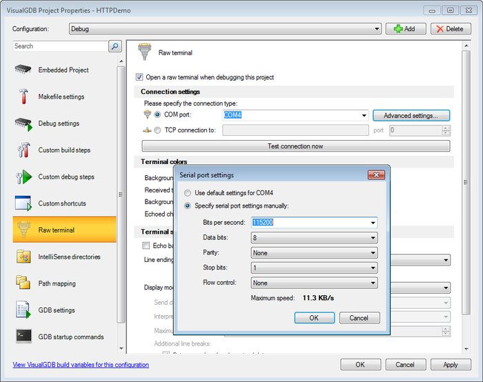
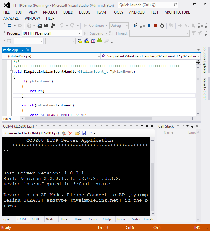
- Go back to Visual Studio, right-click on the project in Solution Explorer, select VisualGDB Project Properties, go to the Raw Terminal page and enable the terminal on the COM port you noted before. Ensure the baud rate is set to 115200:
- Remove the jumper from J15 and put it back between VCC and P58. Press F5 to start debugging your project. The firmware will output some basic status information to the terminal:
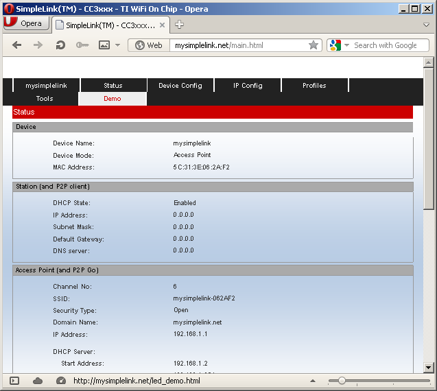
- Use a computer or a phone with WiFi capability to connect to the WiFi network reported by the board. Then open mysimplelink.net/main.html in a browser (just mysimplelink.net opens a page from a different project):
- Click the Demo link and then click the On and Off labels on the Demo page:
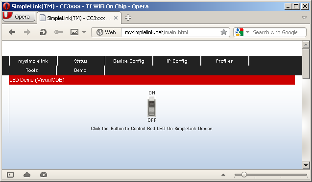
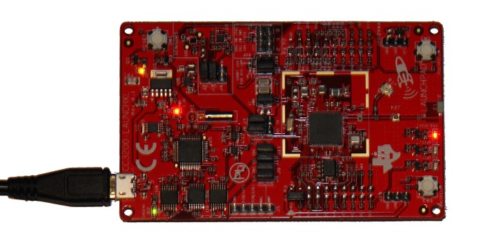
- See how the red LED on the board goes on and off:
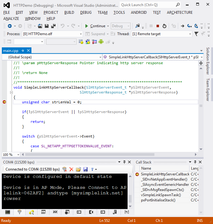
- Put a breakpoint in the SimpleLinkHttpServerCallback() function in Visual Studio and click the ON or OFF label in the browser. The breakpoint will be triggered:
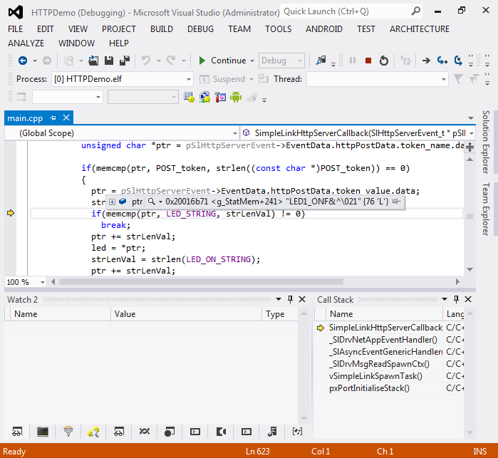
- Step through the method to see how the sample program extracts the data about the HTTP request:
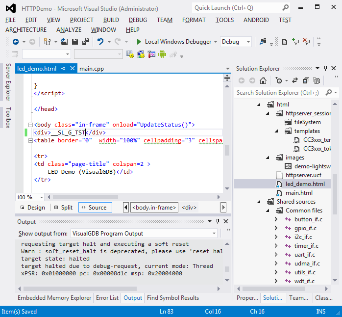
- The actual HTTP requests are handled by the second core of the CC3200 chip that is not directly exposed to our firmware. Instead, the firmware exchanges messages with the core by using the SImpleLink APIs included in the CC3200 SDK. We will now modify the sample to pass one additional message. First, add the following line to the led_demo.html file after the body tag:
<div>__SL_G_TST</div>
- Reprogram the serial FLASH memory using the UniFlash tool (don’t forget to move the jumper to J15 and back):
- Then modify the C source accordingly. Find the call to memcmp(pSlHttpServerEvent->EventData.httpTokenName.data in main.cpp and add the following code before it:
if (!memcmp(pSlHttpServerEvent->EventData.httpTokenName.data,
       "__SL_G_TST", strlen("__SL_G_TST")))
{
    constchar *pReply = "Hello, World!";
    strcpy((char *)ptr, pReply);
    pSlHttpServerResponse->ResponseData.token_value.len +=
                strlen(pReply);
}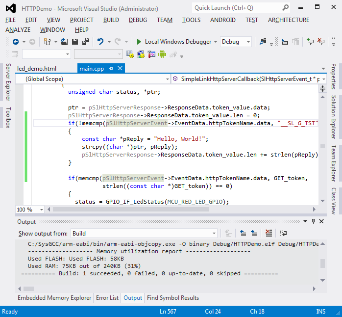
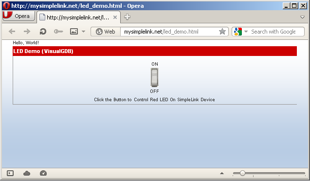
- Start debugging by pressing F5, update the page in the browser and see how “Hello, World” is now displayed on top of the page:
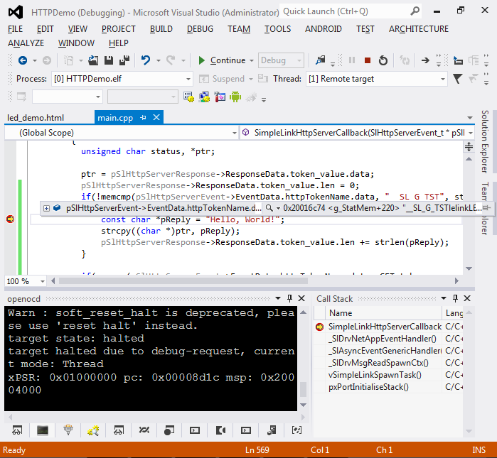
- If you set a breakpoint in the new code and refresh the page again, you can explore the values of other fields of the message sent from the HTTP server to your firmware:


Once you are done experimenting with the HTTP server, you can check out other samples available through the project wizard, like the TCP socket sample or the email sending sample.