Developing FRDM-KL25Z firmware with Visual Studio
This tutorial shows how to make a basic ‘Blinking LED’ project for the FRDM-KL25Z development platform with Visual Studio using the VisualGDB add-in.
Before you begin ensure that you have VisualGDB 4.1 or later installed.
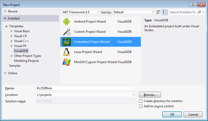
- Launch Visual Studio. Start creating a new project with VisualGDB Embedded Project Wizard:
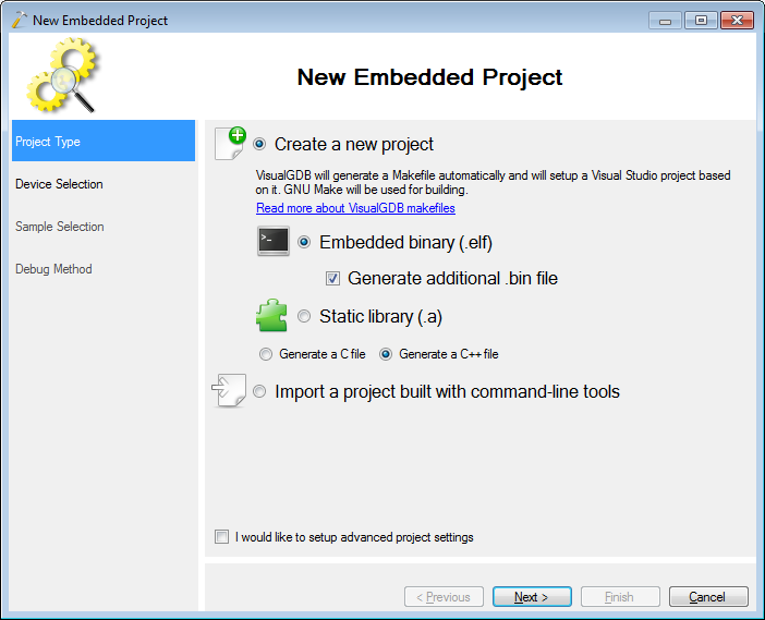
- Proceed with the default settings (Embedded binary) on the first page:
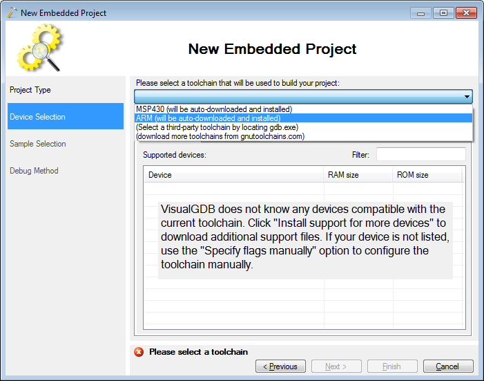
- On the second page select the arm-eabi toolchain. If it is not installed, VisualGDB will automatically download and install it for you:
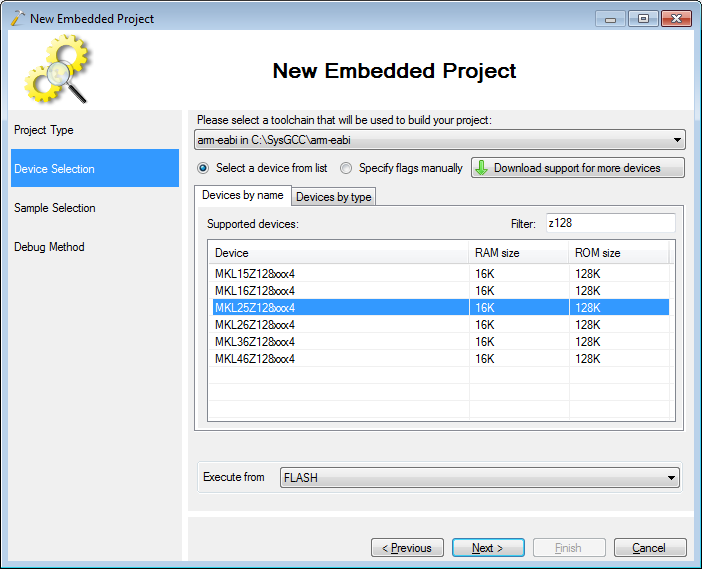
- If you have not created Kinetis projects before, click “Download support for more devices” and select “Freescale Kinetis”. Once the Kinetis files are available, select the MK25Z128xxx4 device from the list:
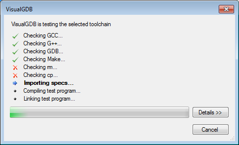
- Once you press “Next”, VisualGDB will test the toolchain and ensure that it can create projects with the selected settings:
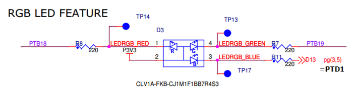
- VisualGDB will generate a basic “Blinking LED” project for you after you specify the LED port on the next page of the wizard. According to FRDM-KL25Z schematics, the red LED is connected to PTB18:
 To make the example blink the red LED select PTB as the port group and 18 as the port number:
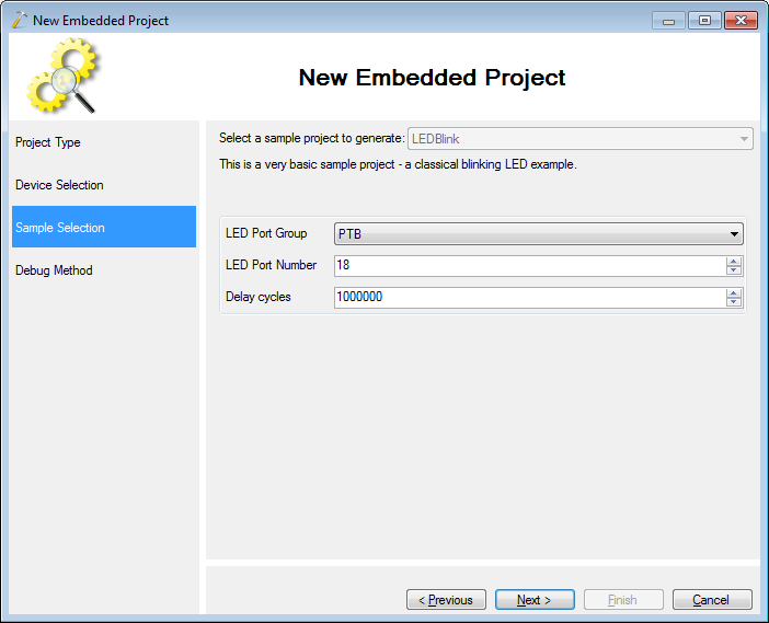
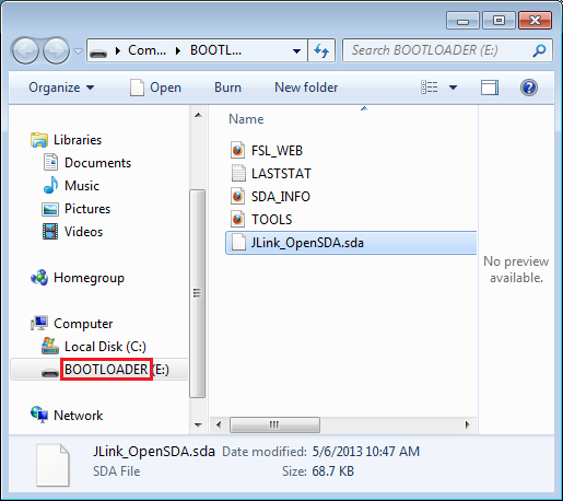
- The last page allows configuring debug settings. The FRDM-KL25Z board is equipped with the OpenSDA circuit that can itself be programmed to emulate various hardware debuggers. In this tutorial we will use the Segger J-Link firmware and show how to use the Segger tools. Hold the reset button on the board and plug it into the USB port while holding the button (use the lower connector labeled as SDA). A new drive called ‘BOOTLOADER’ will appear in Explorer.
- Download the Segger firmware from this page, unpack the archive and drag-n-drop it to the ‘BOOTLOADER’ drive:
 Warning: if the drive label is not ‘BOOTLOADER’, you were not holding the ‘Reset’ button while plugging in the device. Do not copy the OpenSDA file in non-bootloader mode as it will be programmed into your KL25 microcontroller instead.
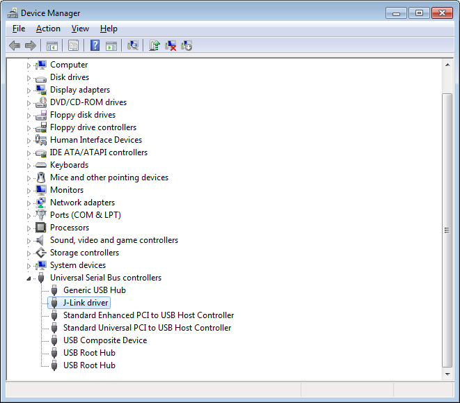
 - Download and install the Segger J-Link software package. Reconnect your board and ensure that it is detected as “Segger J-Link” and that the Segger drivers are installed for it (the drivers will be available in the Segger directory in Program Files):
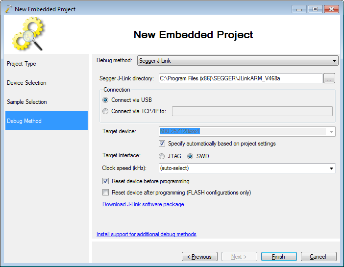
- Go to the Debug Method page in the wizard, specify the location of the J-Link software and select SWD as the target interface:
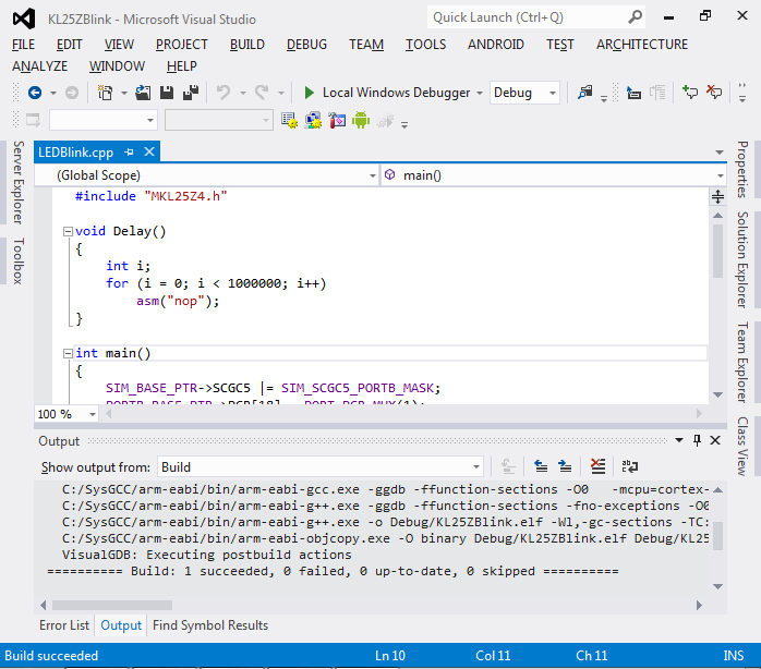
- Press the “Finish” button. VisualGDB will generate a Visual Studio project for the FRDM-KL25Z board. Build it by pressing Ctrl-Shift-B:
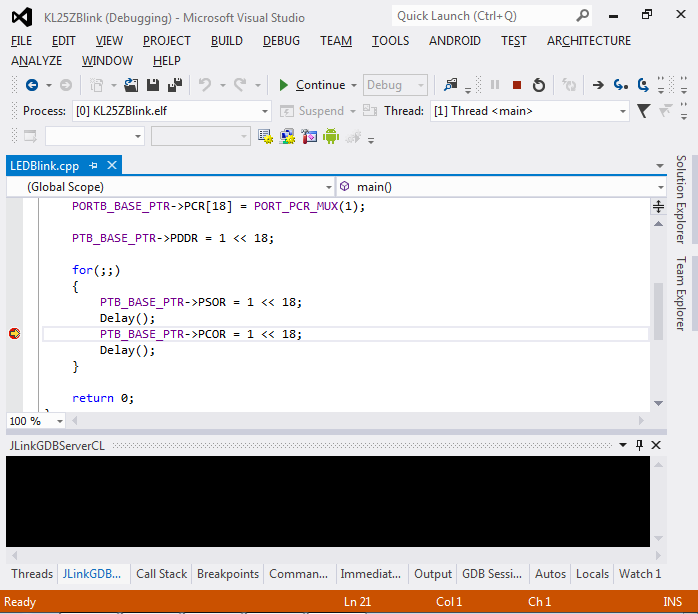
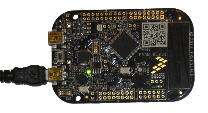
- Press F5 to start debugging. The red part of the RGB LED will start blinking. Put a breakpoint at the line setting the PTB_BASE_PTR->PCOR register and wait until the breakpoint is hit:
- Look at the board. The RGB LED will be inactive:
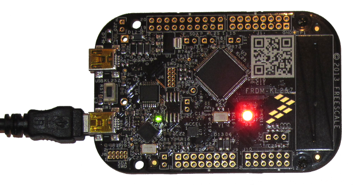
- Press F10 to step over the current line. This will write the value of 1 into the 18th bit of the PTB_PCOR register, switching it to outputting 0 and lighting up the red part of the LED (as the other side of it is connected to +3.3V):
- Press Shift-F5 to stop debugging.


