Using STM32 timers in PWM mode
This tutorial shows how to configure the STM32 hardware timers to generate output signals. The mode in which the timers generate the output signals is called PWM (pulse-width modulation) referring to the pulses of adjustable width that can be generated as a result.
Before you begin with this tutorial please create a basic project for your STM32 device (e.g. by following this tutorial for STM32F1 series devices or this tutorial for the STM32F4-Discovery board).
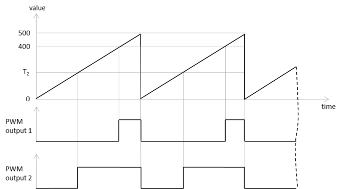
- The STM32 hardware timers are separate hardware blocks that can count from 0 to a given value triggering some events in between. In the PWM mode the timer controls the output of 1 or more output channels. When the counter value reaches 0, maximum or a compare value defined for each channel, the output value of the channel can be changed. Various configuration options define which events change the value and how it is changed.
- Before we can use the PWM mode, we need to setup the timer so that it starts counting. We will configure it to count upwards with a period of 1000 and set the divider to 1 and the prescaler to 40000. This is done by calling the TIM_TimeBaseInit() function followed by a call to TIM_Cmd() to enable the timer:
void InitializeTimer(int period = 500) { RCC_APB1PeriphClockCmd(RCC_APB1Periph_TIM4, ENABLE); TIM_TimeBaseInitTypeDef timerInitStructure; timerInitStructure.TIM_Prescaler = 40000; timerInitStructure.TIM_CounterMode = TIM_CounterMode_Up; timerInitStructure.TIM_Period = period; timerInitStructure.TIM_ClockDivision = TIM_CKD_DIV1; timerInitStructure.TIM_RepetitionCounter = 0; TIM_TimeBaseInit(TIM4, &timerInitStructure); TIM_Cmd(TIM4, ENABLE); } - On the STM32F4Discovery board the main LEDs are connected to pins PD12-PD15 having channels 1-4 of timer 4 as the alternate function #2.
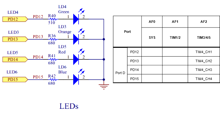
- We will now configure the timer to generate 80% impulses on LED4 (i.e. active for 4/5 of the period and inactive for the next 1/5). This is done by configuring the channel 1 in the PWM mode with a compare value of 400 (out of period 500) and selecting alternate function 2 (AF2) for the pin PD12:
void InitializePWMChannel() { TIM_OCInitTypeDef outputChannelInit = {0,}; outputChannelInit.TIM_OCMode = TIM_OCMode_PWM1; outputChannelInit.TIM_Pulse = 400; outputChannelInit.TIM_OutputState = TIM_OutputState_Enable; outputChannelInit.TIM_OCPolarity = TIM_OCPolarity_High; TIM_OC1Init(TIM4, &outputChannelInit); TIM_OC1PreloadConfig(TIM4, TIM_OCPreload_Enable); GPIO_PinAFConfig(GPIOD, GPIO_PinSource12, GPIO_AF_TIM4); } - Note that in the very beginning of our program we want to enable the GPIOD peripheral and configure the pin PD12 to be an output:
void InitializeLEDs() { RCC_AHB1PeriphClockCmd(RCC_AHB1Periph_GPIOD, ENABLE); GPIO_InitTypeDef gpioStructure; gpioStructure.GPIO_Pin = GPIO_Pin_12; gpioStructure.GPIO_Mode = GPIO_Mode_AF; gpioStructure.GPIO_Speed = GPIO_Speed_50MHz; GPIO_Init(GPIOD, &gpioStructure); } - Finally let’s put things together in a main() function:
int main()
{
    InitializeLEDs();
    InitializeTimer();
    InitializePWMChannel();
    for (;;)
    {
    }
}
- Run the program. The green LED will start blinking in short
cycles being on most of the time. Note that the blinking
happens without any extra work from the CPU that is looping
inside the infinite loop in main() :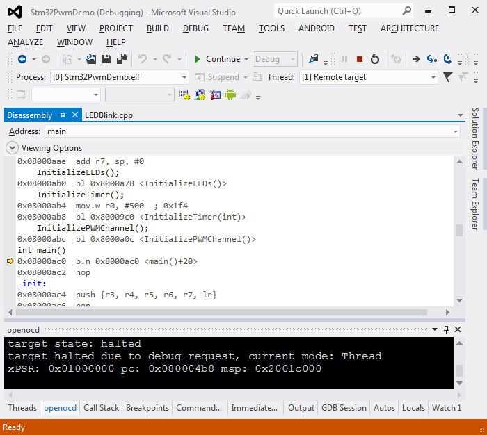 In real-world scenarios this would allow allocating the CPU to do some computation while the pulse generation happens completely in the background.
 - We can easily configure the timer to generate pulse signal on another channel. The period will have to be the same, however the compare value can be different:
void InitializePWMChannel2() { TIM_OCInitTypeDef outputChannelInit = {0,}; outputChannelInit.TIM_OCMode = TIM_OCMode_PWM1; outputChannelInit.TIM_Pulse = 100; outputChannelInit.TIM_OutputState = TIM_OutputState_Enable; outputChannelInit.TIM_OCPolarity = TIM_OCPolarity_High; TIM_OC2Init(TIM4, &outputChannelInit); TIM_OC2PreloadConfig(TIM4, TIM_OCPreload_Enable); GPIO_PinAFConfig(GPIOD, GPIO_PinSource13, GPIO_AF_TIM4); } - In order to test this function we also need to enable PD13 in the InitializeLEDs() function:
gpioStructure.GPIO_Pin = GPIO_Pin_12 | GPIO_Pin_13;
- If you run the modified program now, you will see how both LEDs are blinking with the same period, however the orange LED blinks with much shorter impulse lengths than the green LED.


You can download the full source code of this sample here: PWMDemo.cpp