Developing firmware for STM32L4 devices with Visual Studio
This tutorial hows how to create a project for the STM32L4-Nucleo board using VisualGDB and debug it with OpenOCD.
If you have already used VisualGDB with OpenOCD, update your OpenOCD package to 0.9.0r3 or later via Tools->Embedded Tools Manager.
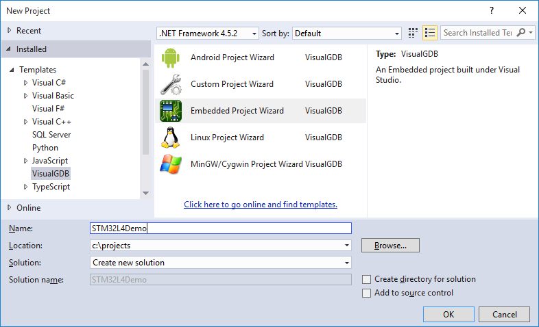
- Start Visual Studio and launch the VisualGDB Embedded project wizard:
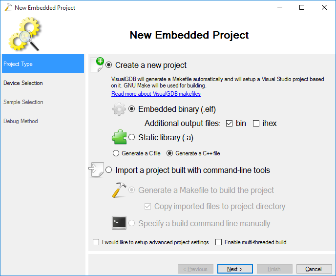
- Select “Create a new project -> Embedded binary” on the first page:
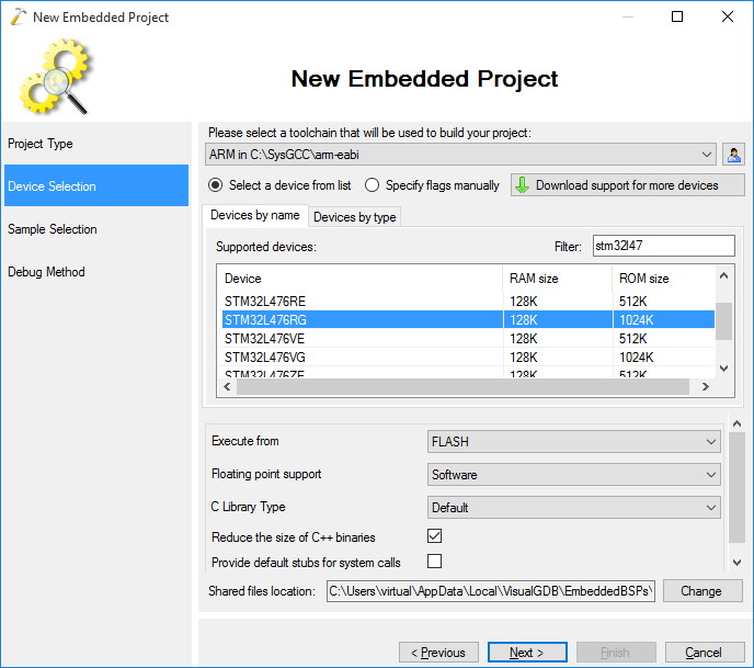
- Select the ARM toolchain and pick the STM32L476 device from the STM32L4-Nucleo board:
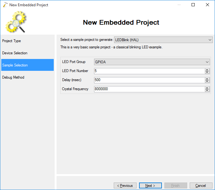
- Proceed with the default LEDBlink sample and select the GPIOA – 5 as the LED port:
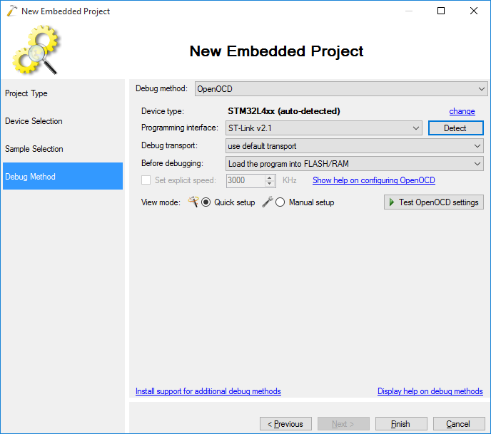
- Select OpenOCD as the debug method. If the STM32L4xx device is not auto-detected, you are not using the latest OpenOCD package. You can install the latest one via Tools->Embedded Tools Manager:
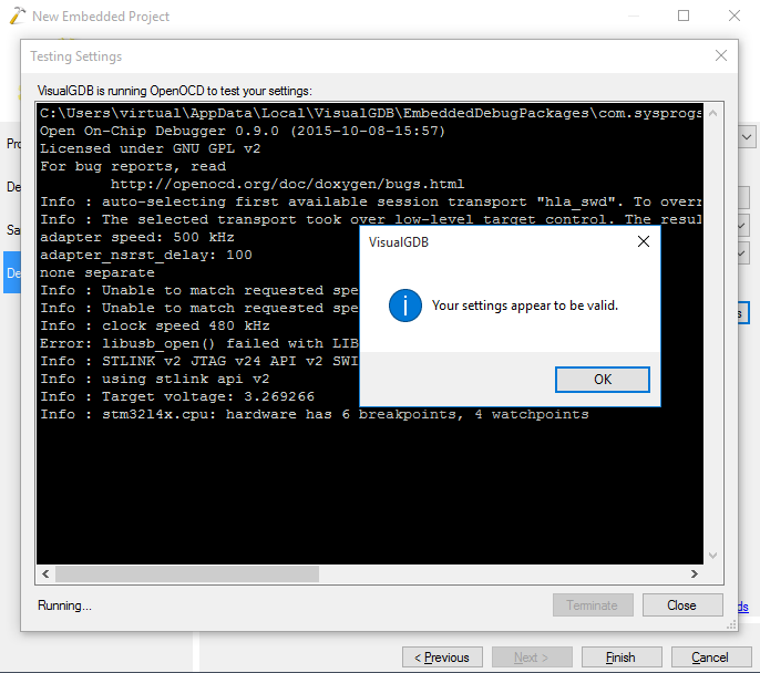
- Click “Test OpenOCD Settings” to check the connection between OpenOCD and the board:
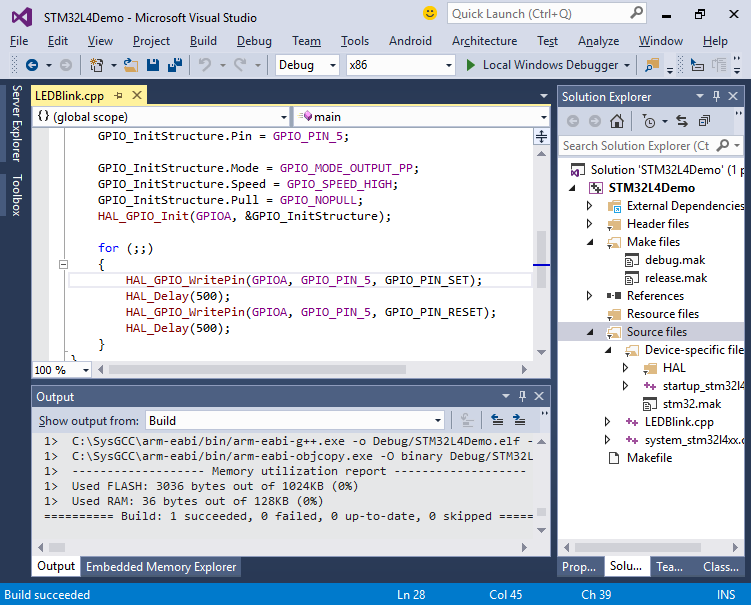
- Once the connection is tested, click “Finish” to create the project. Then press Ctrl-Shift-B to build it:
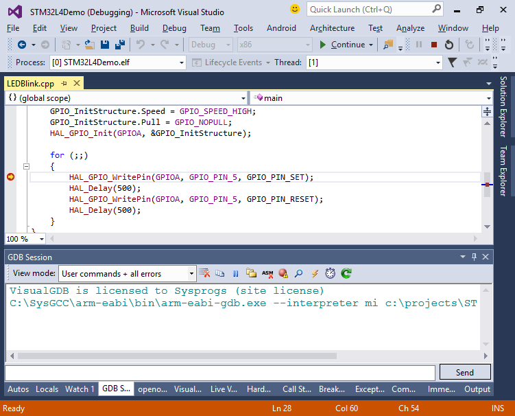
- Set a breakpoint on the first call to HAL_GPIO_WritePin() and press F5 to start debugging. VisualGDB will automatically program your firmware and start debugging:
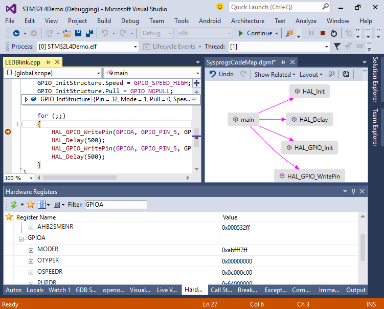
- You can use normal Visual Studio debugging features, view various hardware registers via the Hardware Registers pane and explore the code via Code Map:
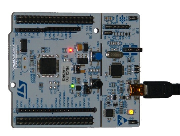
- Step over the call to HAL_GPIO_WritePin(). Observe how the green LED on the board turns on:
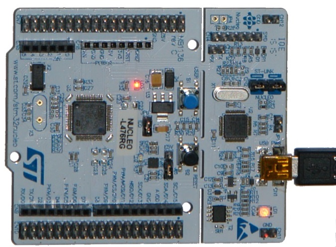
- Once you step over the other call to HAL_GPIO_WritePin(), the LED wil turn off:
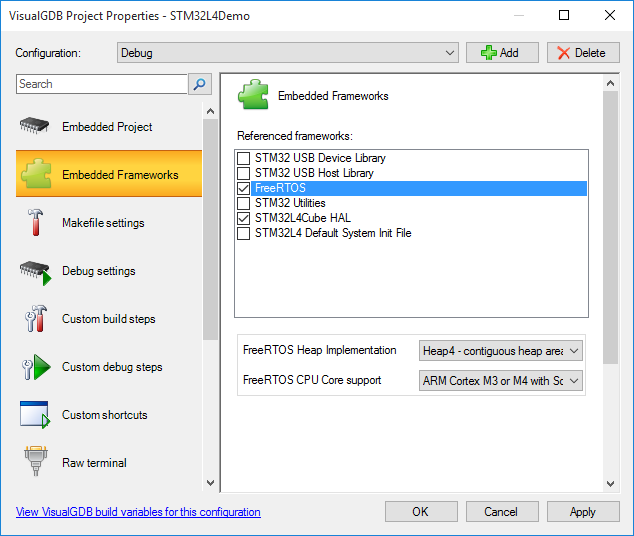
- Press Shift-F5 to stop debugging. You can edit various project properties (e.g. add the FreeRTOS framework) by right-clicking on it in Solution Explorer and selecting VisualGDB Project Properties: