Using the STM32 UART interface
Warning: this tutorial describes a deprecated STM32 StdPeriph API. For detailed instructions on using the new HAL API follow this tutorial.
This tutorial shows how to use the STM32 UART interface to exchange some data with the computer. We will use the STM32F100B-eval board to make a basic firmware that will allow the computer to control onboard LEDs by sending on and off commands. We will use the Olimex ARM-USB-OCD-H JTAG programmer that supports JTAG debugging and contains a USB-to-UART adapter. To use this tutorial you will need Visual Studio with VisualGDB 4.2 or later installed.
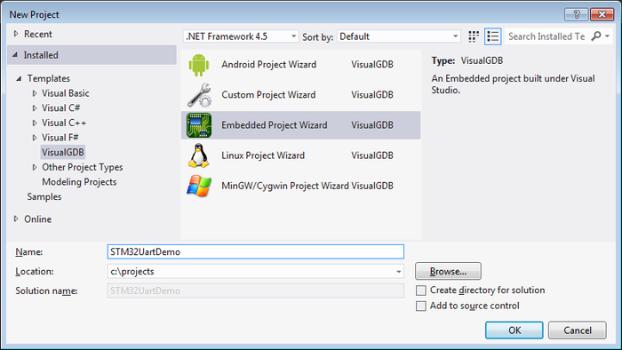
- Start Visual Studio, open VisualGDB Embedded Project Wizard:
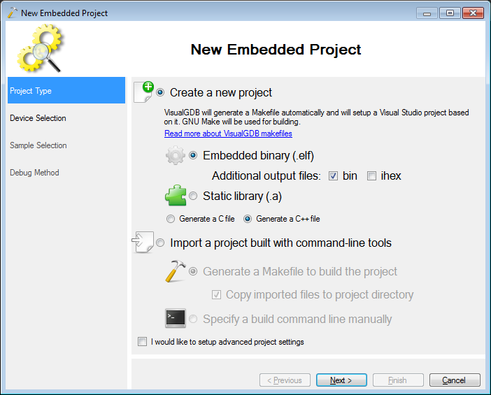
- On the first page of the wizard proceed with the default project type:
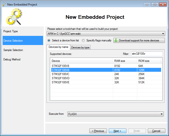
- On the third page select the ARM toolchain and the STM32F100VB device. If you don’t have the toolchain or the BSP, VisualGDB will allow installing them from the wizard:
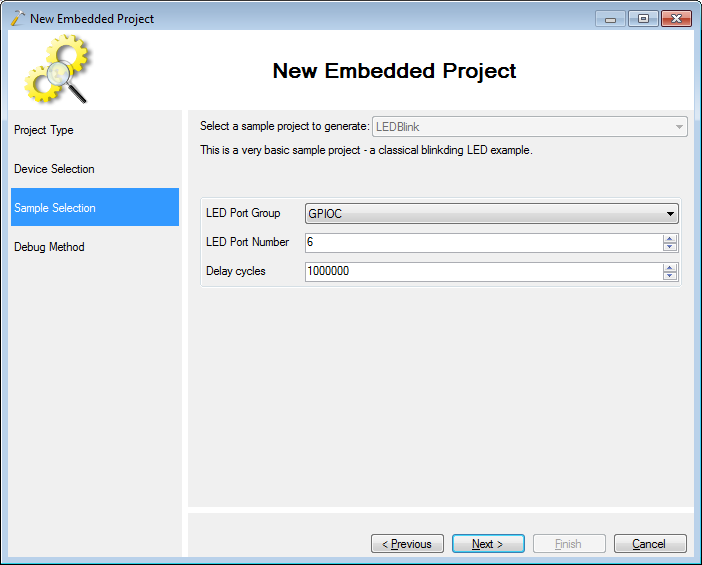
- Proceed with the default “LED Blink” sample:
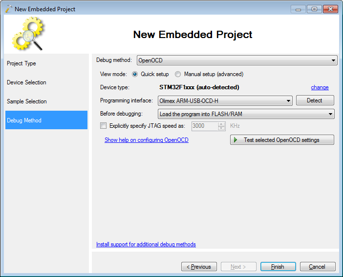
- Select “OpenOCD” as the debug method. Connect your USB programmer and click “Detect”. Then press “Test selected OpenOCD settings” to verify them:
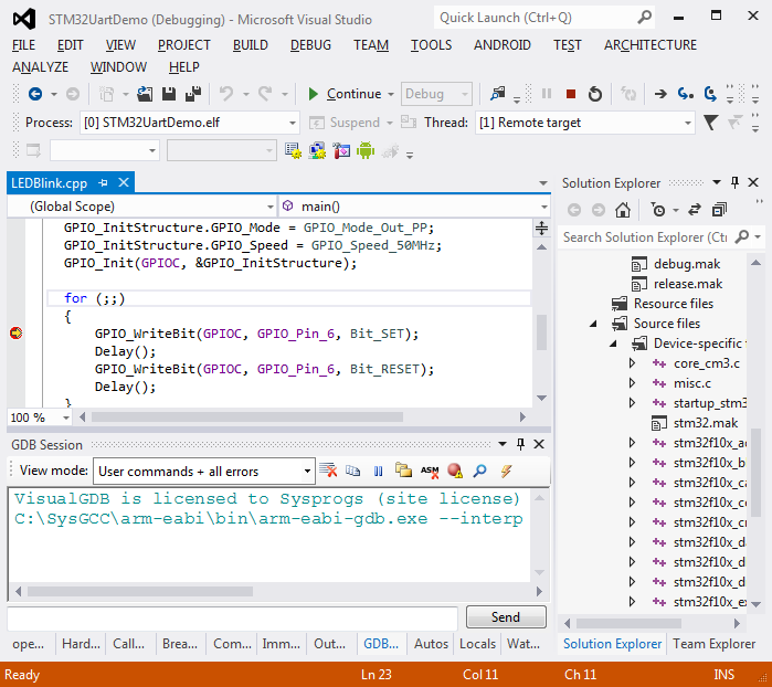
- Press “Finish” to create your project. Build the sample project with Ctrl-Shift-B and ensure you can debug it by pressing F5:
- Now we will add the UART support. Add the following code before your main() function:
#include <stm32f10x_usart.h>

void InitializeUSART()
{
    USART_InitTypeDef usartConfig;

    RCC_APB2PeriphClockCmd(RCC_APB2Periph_USART1 | RCC_APB2Periph_GPIOA | RCC_APB2Periph_AFIO, ENABLE);
    USART_Cmd(USART1, ENABLE);

    usartConfig.USART_BaudRate = 9600;
    usartConfig.USART_WordLength = USART_WordLength_8b;
    usartConfig.USART_StopBits = USART_StopBits_1;
    usartConfig.USART_Parity = USART_Parity_No;
    usartConfig.USART_Mode = USART_Mode_Rx | USART_Mode_Tx;
    usartConfig.USART_HardwareFlowControl = USART_HardwareFlowControl_None;
    USART_Init(USART1, &usartConfig);

    GPIO_InitTypeDef gpioConfig;

    //PA9 = USART1.TX => Alternative Function Output
    gpioConfig.GPIO_Mode = GPIO_Mode_AF_PP;
    gpioConfig.GPIO_Pin = GPIO_Pin_9;
    gpioConfig.GPIO_Speed = GPIO_Speed_2MHz;
    GPIO_Init(GPIOA, &gpioConfig);

    //PA10 = USART1.RX => Input
    gpioConfig.GPIO_Mode = GPIO_Mode_IN_FLOATING;
    gpioConfig.GPIO_Pin = GPIO_Pin_10;
    GPIO_Init(GPIOA, &gpioConfig);
}

unsignedchar USART_ReadByteSync(USART_TypeDef *USARTx)
{
    while ((USARTx->SR & USART_SR_RXNE) == 0)
    {
    }

    return (unsigned char)USART_ReceiveData(USARTx);
}
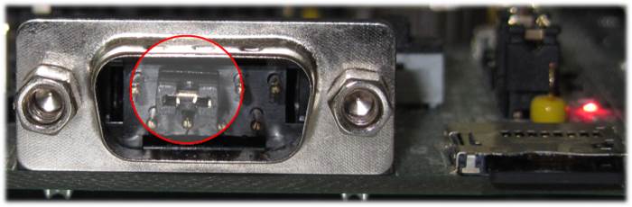
- The easiest way to test the UART interface is to connect the RX and TX pins together and see whether the sent data gets echoed back. Put a jumper between pins 2 and 3 on the USART1 plug:
- Then replace the contents of the for() loop in main() with the code that sends a value of 0x55 to the UART and reads is back:
InitializeUSART();

for (;;)
{
    USART_SendData(USART1, 0x55);
    unsigned char byte = USART_ReadByteSync(USART1);

    asm("nop");
}
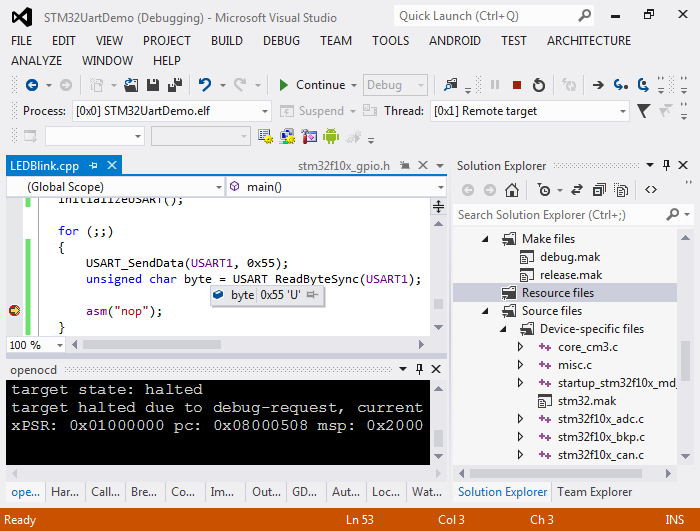
- Put a breakpoint on the “nop” line. Start debugging your firmware. Ensure that your breakpoint hits and the value of ‘byte’ matches the value sent to the UART:
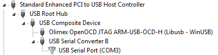
- Install the USB-to-RS232 drivers for the Olimex JTAG programmer. They can be found in the CDM20808 folder in the Olimex driver package. The second device instance should be appear as ‘USB Serial Converter B’ in Device Manager:
- Go to VisualGDB project properties. Enable the Raw Terminal on the COM port displayed in the Device Manager. Set the speed to the same value as you specified in InitializeUSART(). In this example we use 9600:
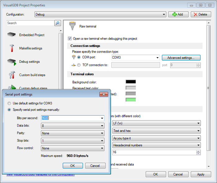 Select the ‘text and hex’ mode and enable echoing of entered characters.
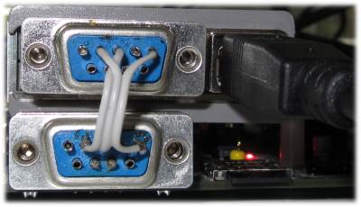
 - Connect the UART port on the Olimex programmer with UART1 on your board. If you don’t have a cable, you can solder one very simply: connect pins #5 (ground), #2 (tx) and #3 (rx). Note that pin #2 on either side should be connected to pin #3 on the other side and vice versa. This ensures that the sender is connected to a receiver on the opposite side:
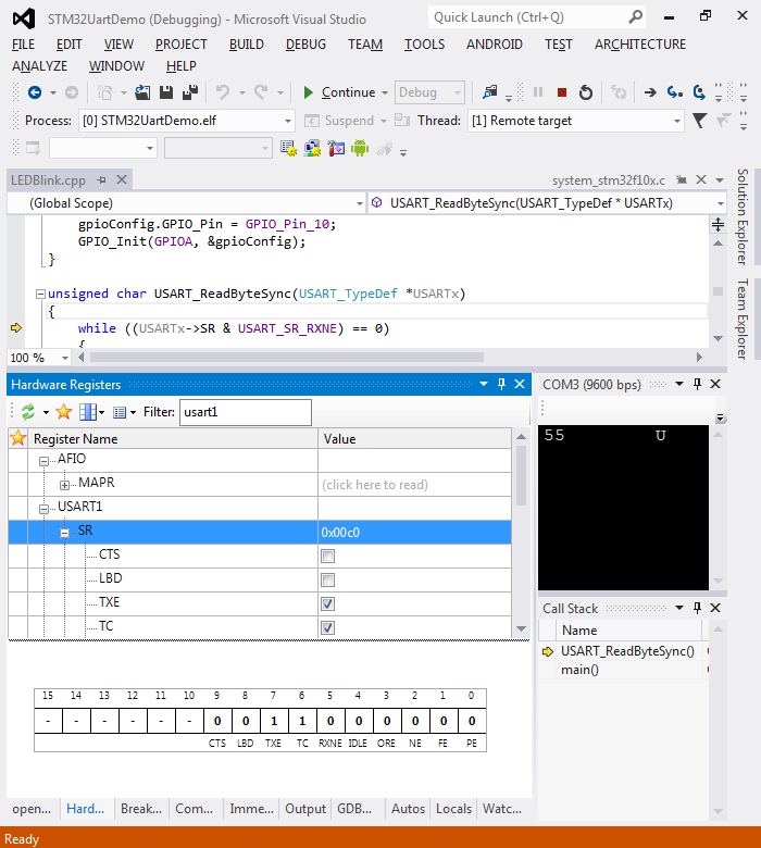
- Start debugging with F5 and open the terminal. You will see the 0x55 character in the raw terminal. Click the ‘break all’ button to see what code is currently running. You will see that your firmware is waiting for a reply on the COM port. You can use the Hardware Registers window to examine the USART module registers:
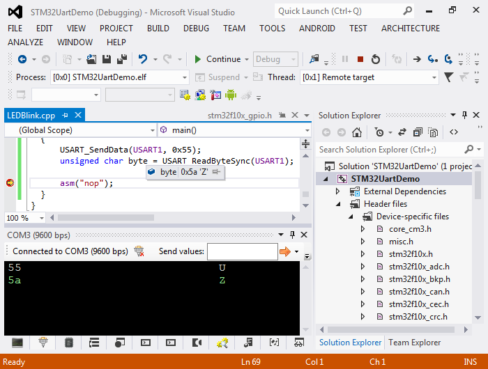
- Press F5 to resume debugging. Type something (e.g. 5A) in reply. See how the reply you typed ended up in the ‘byte’ variable:
 The values of 0x55 and 0x5A are chosen because of their binary representation: 0101 0101 and 0101 1010. If the UART speed is chosen slightly incorrectly and a single bit transmission is longer or shorter than expected and overlaps with the next bit, those values will be received incorrectly giving an early indication of the problem.
 - Now we will add text mode support to our example. We will add a basic interface that will ask for a command and run it. It will support 2 commands: ‘led’ and ‘help’. Replace your main() with the following code:
#include <stdio.h>
#include <string.h>

int main()
{
    GPIO_InitTypeDef GPIO_InitStructure;

    RCC_APB2PeriphClockCmd(RCC_APB2Periph_GPIOC, ENABLE);

    GPIO_InitStructure.GPIO_Pin = GPIO_Pin_6 | GPIO_Pin_7 | GPIO_Pin_8 | GPIO_Pin_9;

    GPIO_InitStructure.GPIO_Mode = GPIO_Mode_Out_PP;
    GPIO_InitStructure.GPIO_Speed = GPIO_Speed_50MHz;
    GPIO_Init(GPIOC, &GPIO_InitStructure);

    InitializeUSART();
    static const int LEDs[] = {GPIO_Pin_6, GPIO_Pin_7, GPIO_Pin_8, GPIO_Pin_9};

    for (;;)
    {
        printf("Enter a command: ");
        char sz[32];
        scanf("%31s", sz);
        if (!strcmp(sz, "help"))
        {
            printf("Supported commands:\r\n");
            printf("\thelp\r\n\tled <number> <on|off>\r\n");
        }
        else if (!strcmp(sz, "led"))
        {
            unsigned number = 0;
            scanf("%d%31s", &number, sz);
            bool on;
            if (!strcmp(sz, "on"))
                on = true;
            else if (!strcmp(sz, "off"))
                on = false;
            else
            {
                printf("Invalid mode: %s\r\n", sz);
                continue;
            }

            if (number <= 0 ||
                number > sizeof(LEDs)/sizeof(LEDs[0]))
            {
                printf("Invalid LED number: %d\r\n", number);
                continue;
            }

           if (on)
               GPIO_SetBits(GPIOC, LEDs[number - 1]);
           else
               GPIO_ResetBits(GPIOC, LEDs[number - 1]);
       }
       else
           printf("Invalid command\r\n");
    }
}
- If you build the project now, the linker complain about certain syscall implementations missing. Here are the most important ones:
- _sbrk dynamically increases the heap size. The heap starts right after the “end” symbol defined by the linker and is extended on demand until a collision with the stack pointer is detected.
- _fstat/_isatty are used to tell the C library that stdout is a console and not a file and should not be buffered excessively.
- _read/_write are called by the C library to actually transfer the data.
Add a new file to the project (e.g. syscalls.cpp) and paste the following code into it:
#include <stdio.h>
#include <sys/stat.h>
#include <stm32f10x_usart.h>

extern "C"
{
    int _fstat (int fd, struct stat *pStat)
    {
        pStat->st_mode = S_IFCHR;
       return 0;
    }

    int _close(int)
    {
       return -1;
    }

    int _write (int fd, char *pBuffer, int size)
    {
        for (int i = 0; i < size; i++)
        {
            while (!(USART1->SR & USART_SR_TXE))
            {
            }
            USART_SendData(USART1, pBuffer[i]);
        }
        return size;
    }

    int _isatty (int fd)
    {
       return 1;
    }

    int _lseek(int, int, int)
    {
       return -1;
    }

    int _read (int fd, char *pBuffer, int size)
    {
        for (int i = 0; i < size; i++)
        {
            while ((USART1->SR & USART_SR_RXNE) == 0)
            {
            }

            pBuffer[i] = USART_ReceiveData(USART1);
        }
        return size;
    }

    caddr_t _sbrk(int increment)
    {
       extern char end asm("end");
       register char *pStack asm("sp");

       static char *s_pHeapEnd;

       if (!s_pHeapEnd)
            s_pHeapEnd = &end;

       if (s_pHeapEnd + increment > pStack)
            return (caddr_t)-1;

        char *pOldHeapEnd = s_pHeapEnd;
        s_pHeapEnd += increment;
        return (caddr_t)pOldHeapEnd;
    }
}
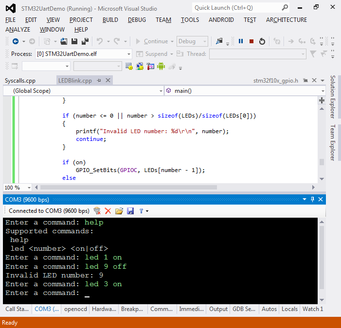
- Switch the Raw Terminal to text mode, build your firmware and start debugging. Enter some commands and observe the LEDs:
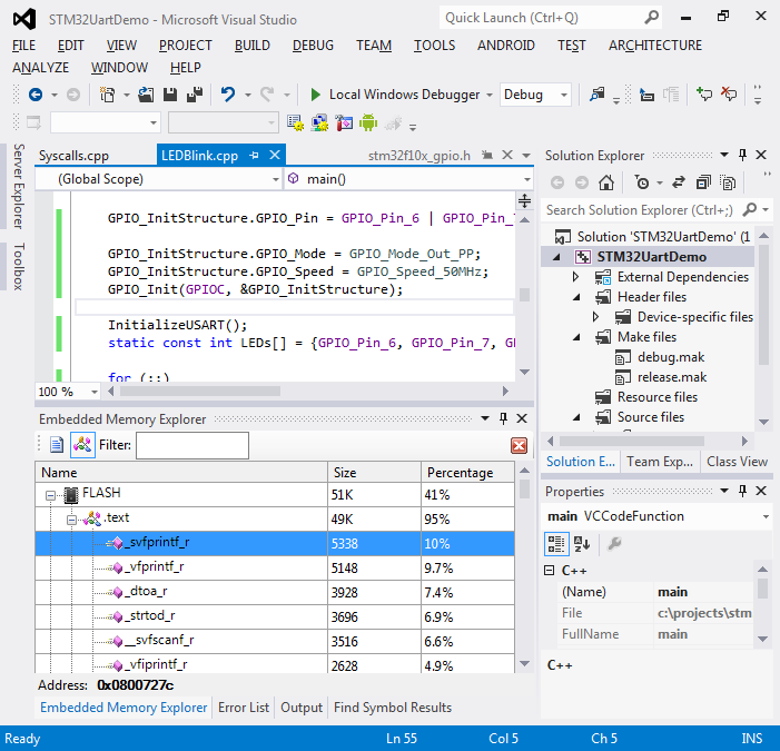
- You can use the Embedded Memory Explorer window to analyze the footprint of your firmware. By analyzing the footprint of this example you can see that adding text mode support considerably increased the code size due to heavy functions related to sprintf():