Developing for the XMC2Go Kit with Visual Studio
This tutorial shows how to develop firmware for the Infineon XMC2Go kit with Visual Studio and VisualGDB. Before you begin, install VisualGDB.
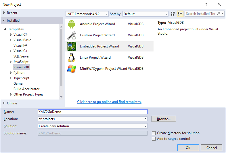
- Start Visual Studio and begin creating a new project with the VisualGDB Embedded Project Wizard:
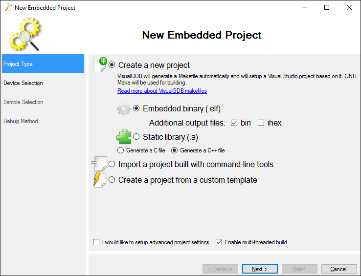
- Proceed with the default “Embedded Binary” selection:
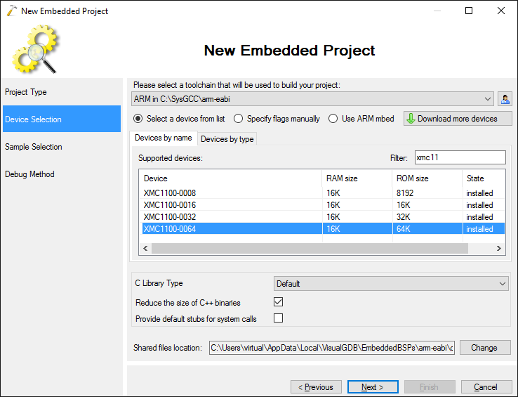
- On the “Device Selection” page select the ARM toolchain and pick the XMC1100-0064 device that is installed on the XMC2Go kit. If this is the first time you are creating a project for Infineon devices, VisualGDB will download all the necessary files automatically:
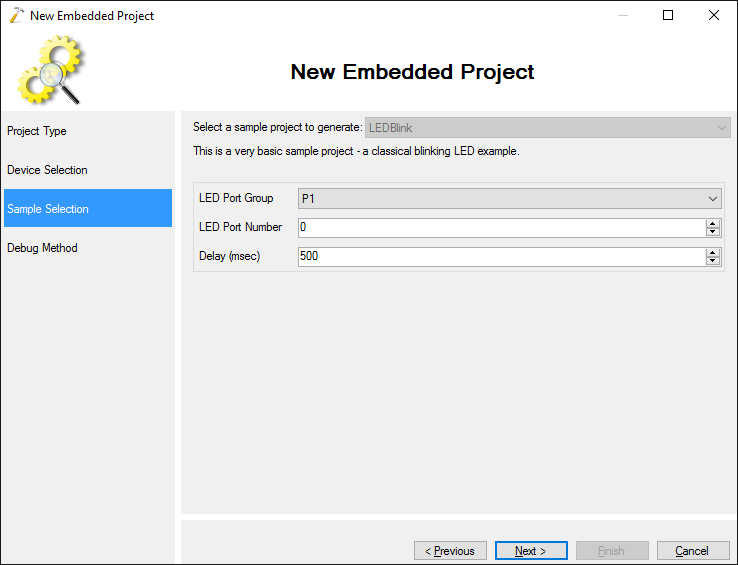
- On the Sample Selection page proceed with the default LEDBlink sample and select the P1_0 pin where the LED on the XMC2Go module is connected:
- The module comes with an on-board Segger J-Link debugger, so simply select the Segger debug method from the list and press “Finish” to generate your project:
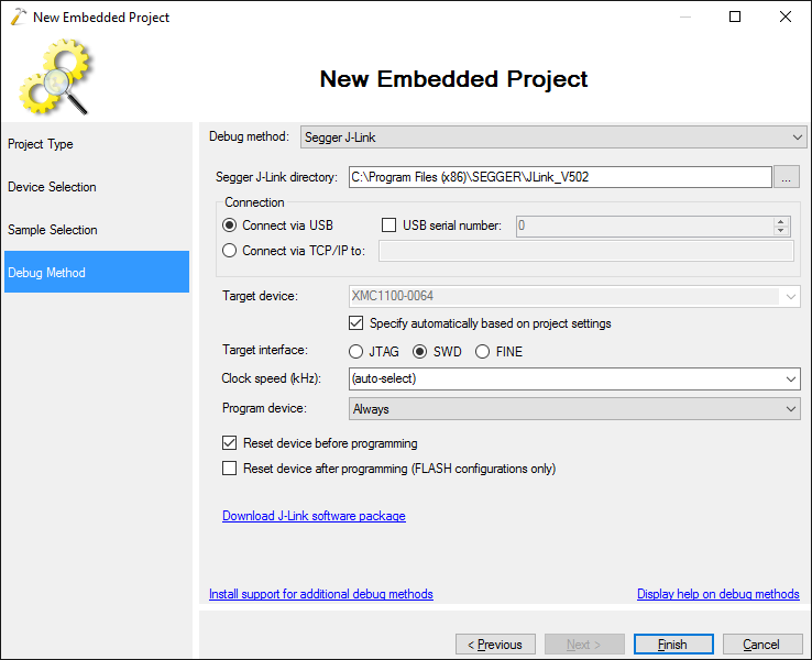 Note that the older releases of the Segger software package sometimes cannot program the XMC2Go board correctly. Please ensure you are using the latest one (v5.12 or later).
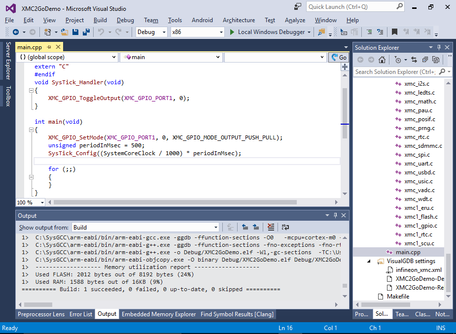
 - Once the project is generated, you can build it by pressing Ctrl-Shift-B:
- Connect your module to the USB port, ensure the Segger drivers are installed and press F5 to start debugging. The red LED in the corner of the module will start blinking:

- Set a breakpoint in the SysTick_Handler() function and wait for it to trigger. Then use the Hardware Registers window to locate the P1->OUT register:
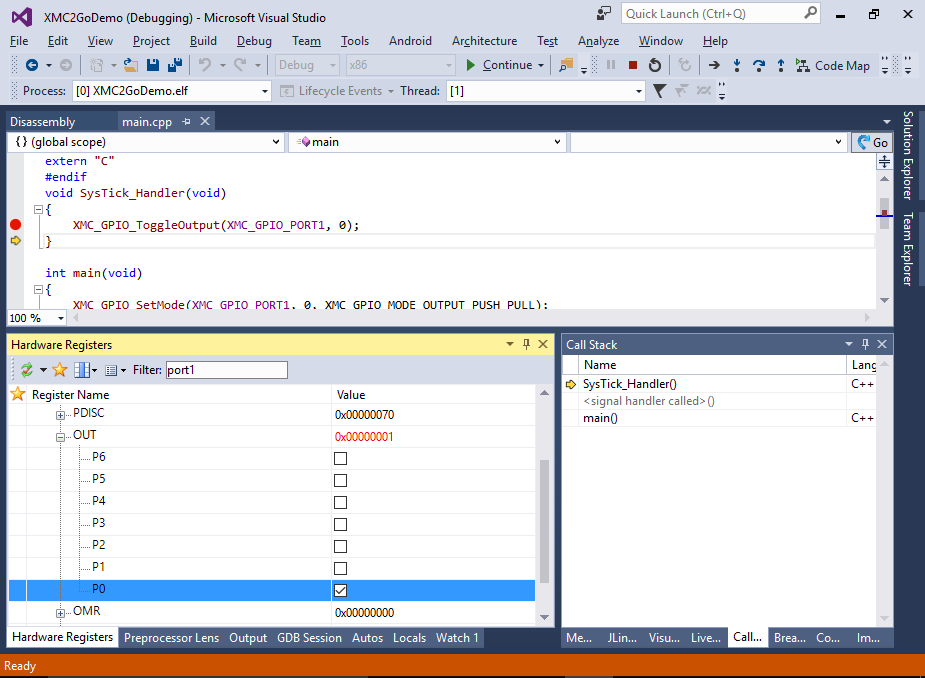
- You can use the Hardware Registers window to see how the register values change when various functions are called and you can also modify the register values manually. E.g. you can set the P0 checkbox to manually set the pin state to high:
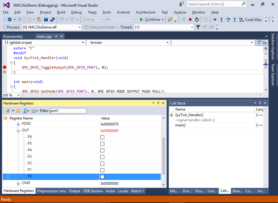
- Note how this turns off the LED:

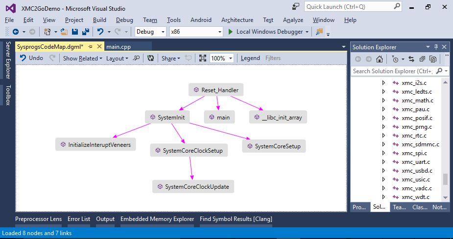
- You can use the Code Map feature provided by VisualGDB’s Clang-based IntelliSense engine to quickly visualize relations between your functions. E.g. you can quickly plot how the Reset_Handler() calls SystemInit() that calls SystemCoreClockSetup() and a few other functions:
