Making a basic USB CDC project for STM32F4Discovery
This tutorial shows how to create a basic USB communication device using the STM32F4Discovery board. The USB protocol stack implementation is contained in the STM32CubeF4 firmware package and is included in our latest STM32 package.
Before you begin, install VisualGDB 5.0 or later and get the latest version of the STM32 BSP via Embedded Tools Manager in Visual Studio Tools menu.
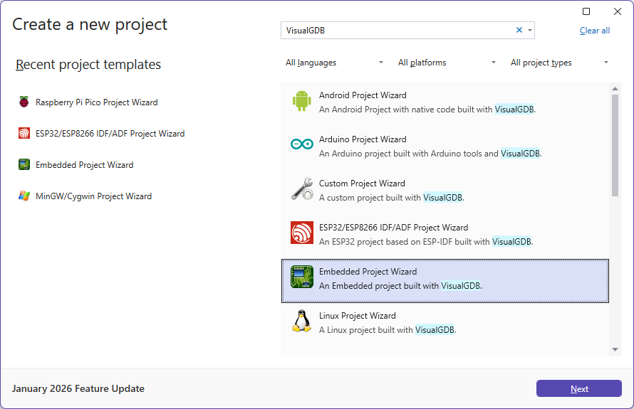
- Start Visual Studio, open VisualGDB Embedded Project Wizard:
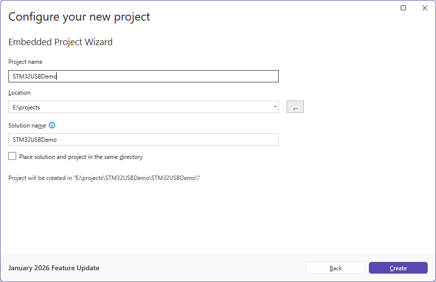
- Enter the name and location of your project:
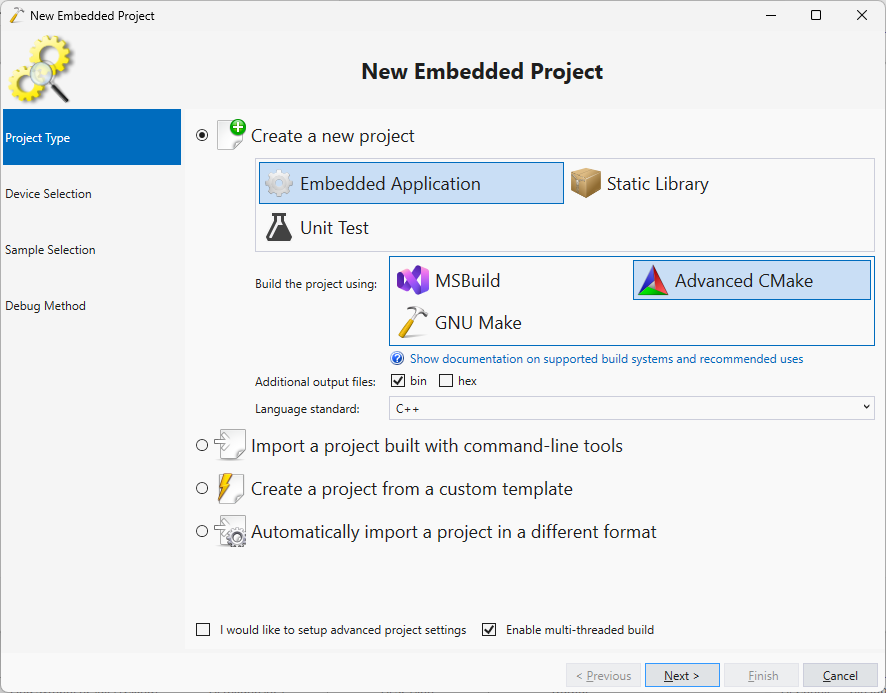
- The first page of the wizard allows selecting the project type. Proceed with the default settings:
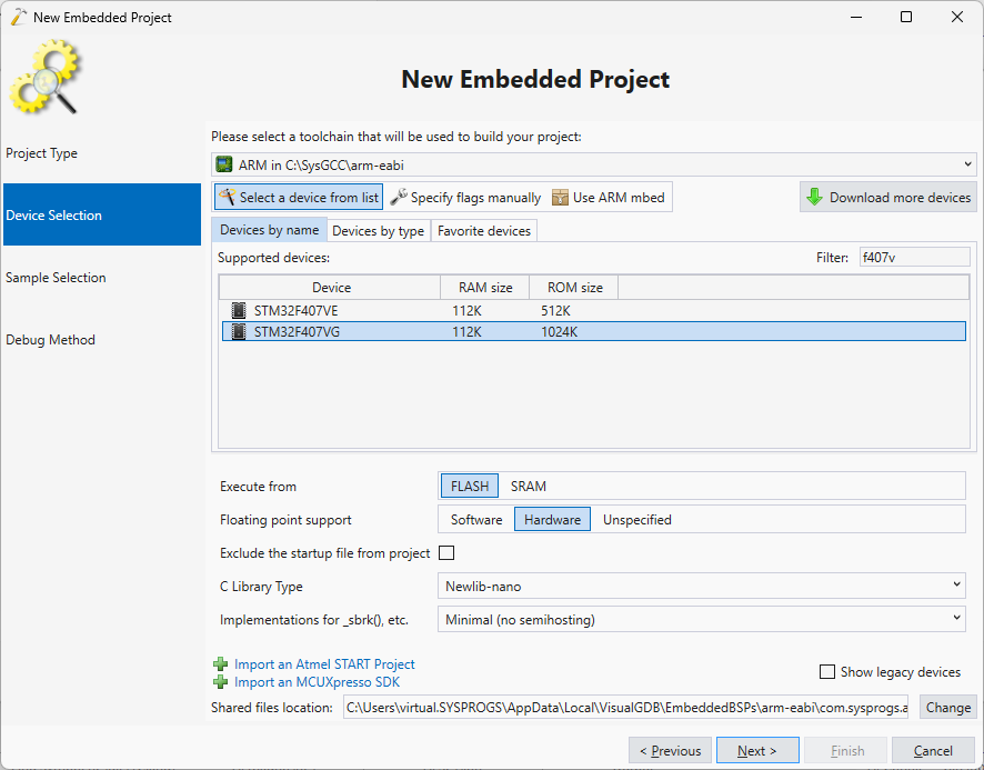
- Select your STM32 device on the second page of the wizard:
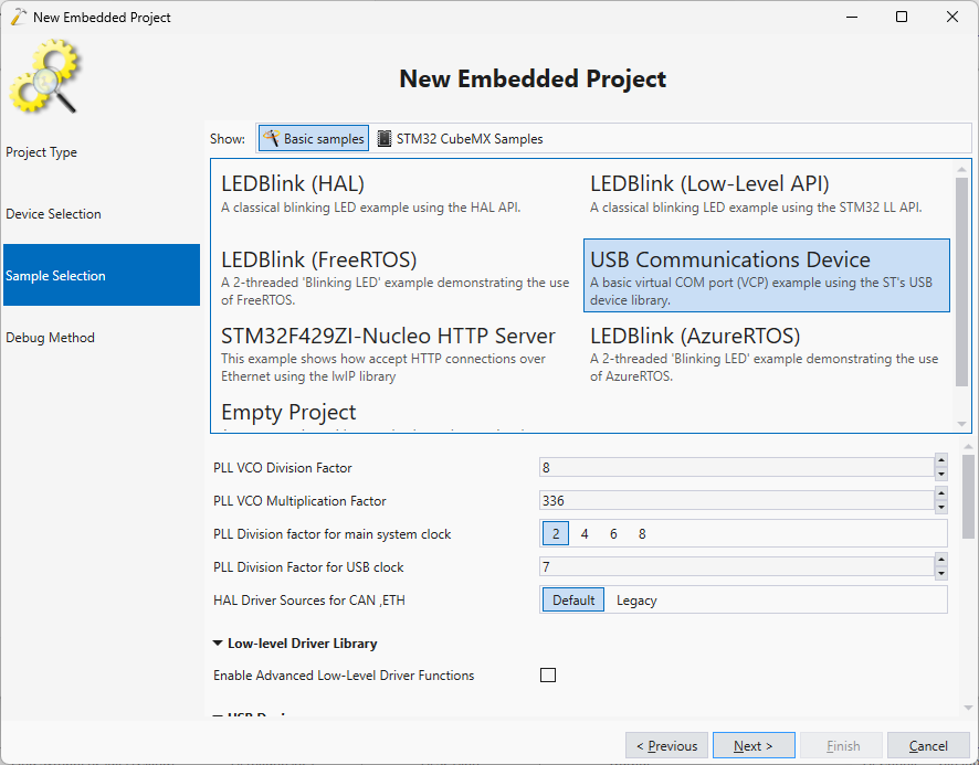
- Specify the PLL configuration for your board. You can find the values by running the STM32CubeMX code generator or looking up the ST samples. You can modify the values later as well:
- Select OpenOCD on the debug method page. Connect your board and select the ST-Link as the debug method. Press ‘Test settings’ to verify the connection to the board:

- Press “Finish” to create the project. Build it by pressing Ctrl-Shift-B:
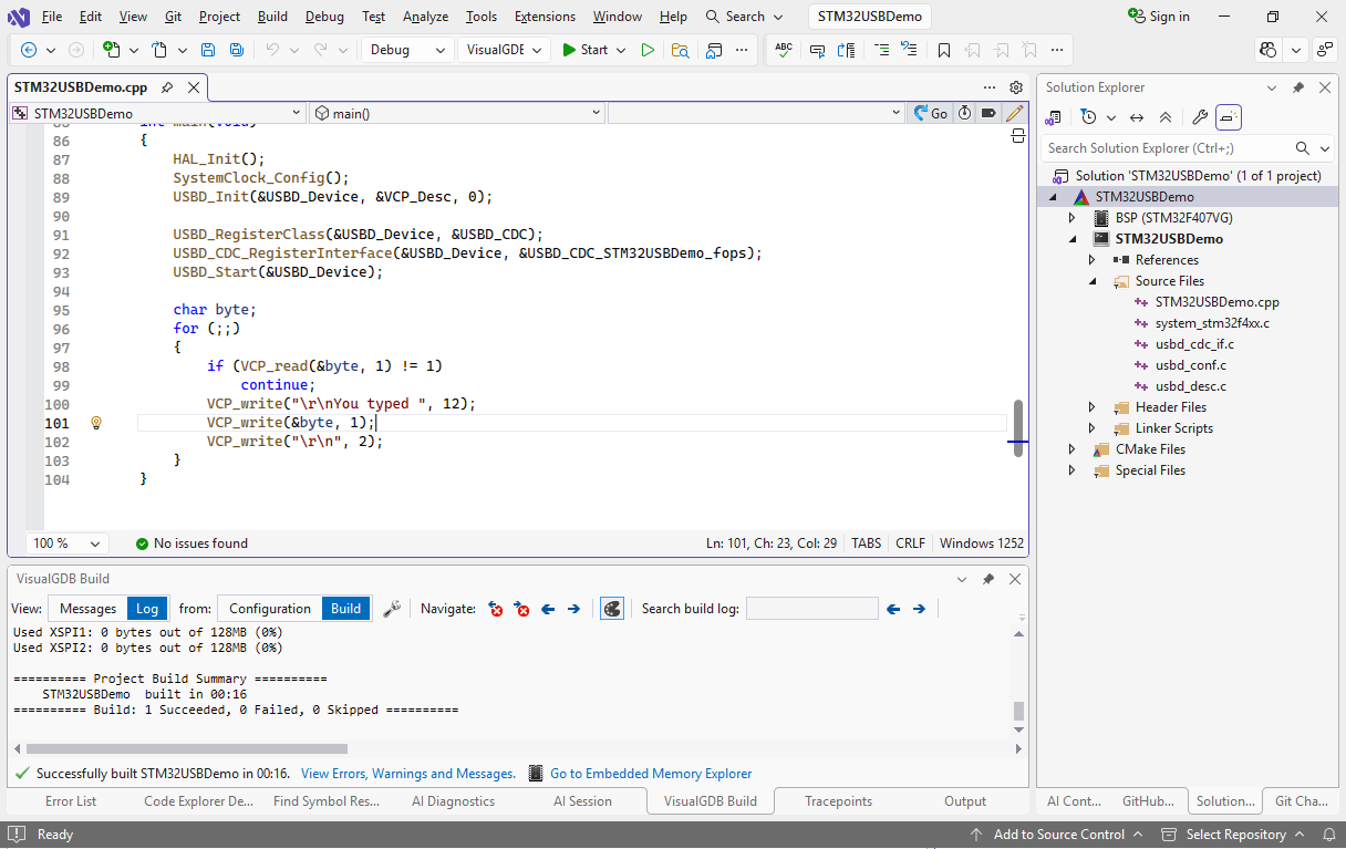 If you want to modify the PLL values now, simply edit the SystemClock_Config() function.
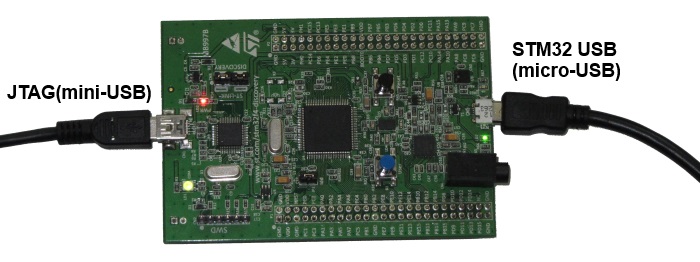
 - Connect your board using both USB sockets. Note that the mini-USB socket is needed for JTAG debugging and the micro-USB socket is connected to the STM32F407 microcontroller itself:
- Press Ctrl-F5 to program the device without debugging it. You should see a new COM port appear in the device list:
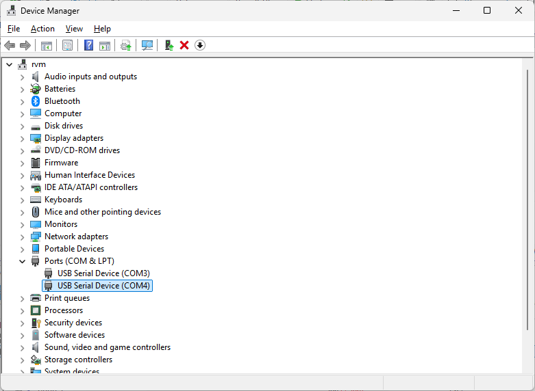 Take a note of the COM port number assigned to the device.
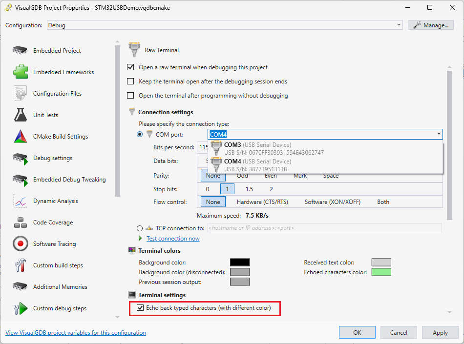
 - Now we will test our firmware. Go to VisualGDB Project Properties and enable the raw terminal on the device COM port. Set the mode to ‘text only and enable character echoing:
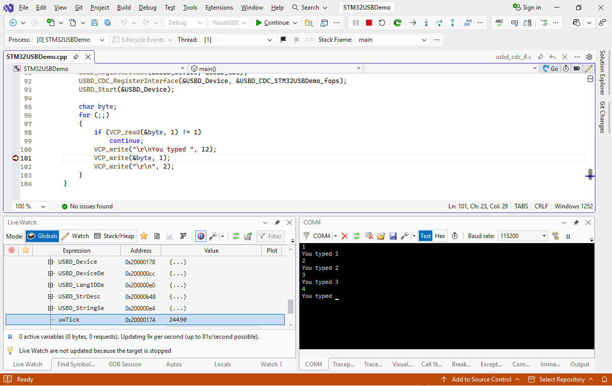
- Build your project and press F5 to start debugging. Open the raw terminal and type something there. See how the ‘you typed’ lines are sent by the device. You can also set breakpoints, step and inspect variable values like when debugging normal programs:
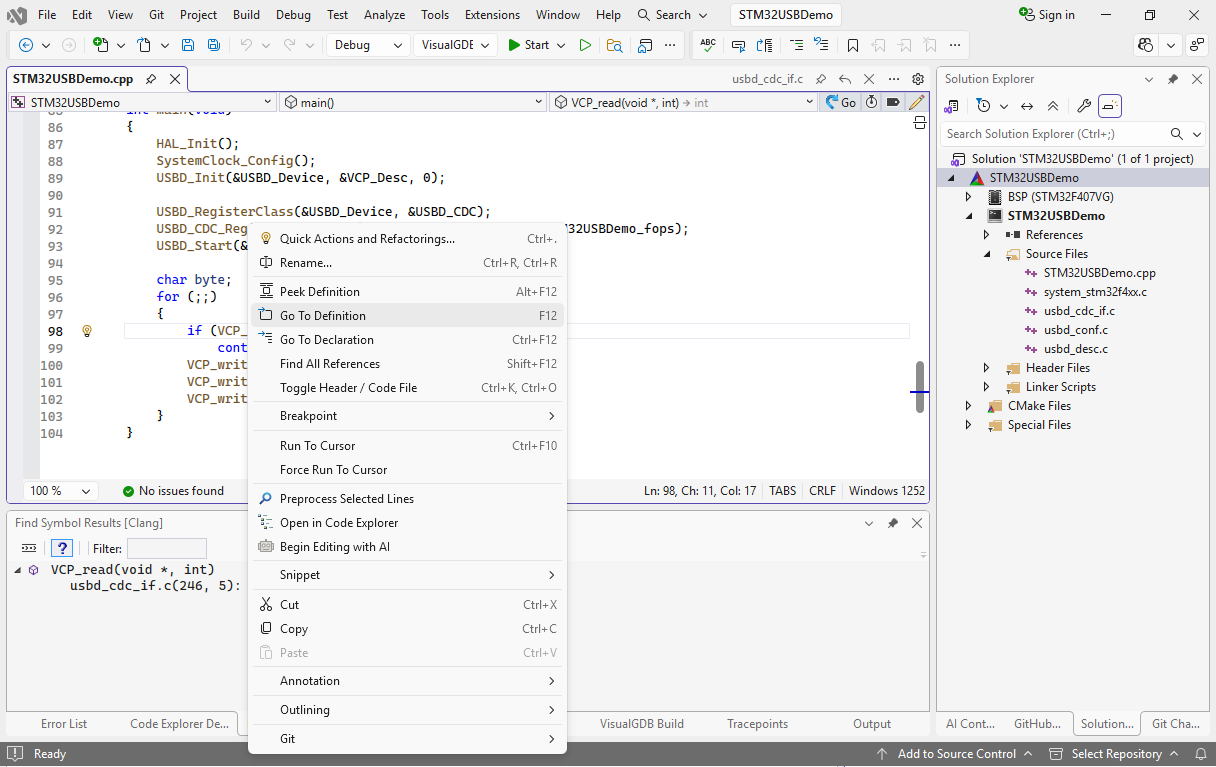
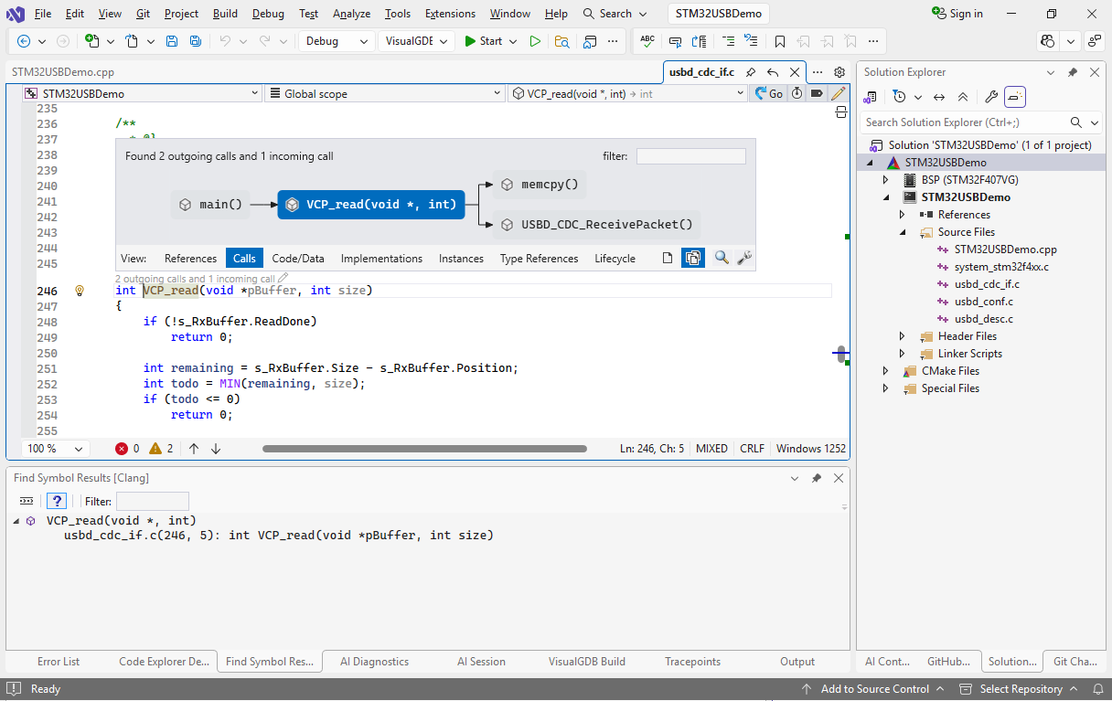
- Now we will use the CodeJumps feature to quickly visualize the functions involved in receiving the data over USB. Right-click on VCP_read() and select “Go To Definition”:
- Click on the link on top of VCP_read and switch the view into the “Calls” mode. It will show hot VCP_read() calls USBD_CDC_ReceivePacket():
- Now we will demonstrate how to use the USB CDC interface with the standard library functions like printf(). Replace the loop in main() with the following:
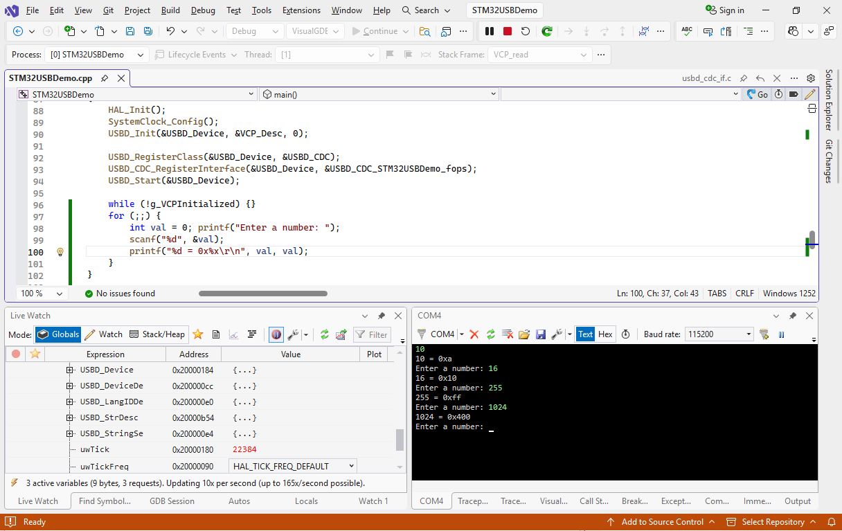
while (!g_VCPInitialized) {} for (;;) { int val = 0; printf("Enter a number: "); scanf("%d", &val); printf("%d = 0x%x\r\n", val, val); } - If you try to build your project now, the default implementations of the I/O functions will use the debug-only semihosting interface to handle functions like printf(). We can override this behavior by providing our own implementations for the functions below:
#include<sys/stat.h> extern"C" { int _fstat (int fd, struct stat *pStat) { pStat->st_mode = S_IFCHR; return 0; } int _close(int) { return -1; } int _write (int fd, char *pBuffer, int size) { return VCP_write(pBuffer, size); } int _isatty (int fd) { return 1; } int _lseek(int, int, int) { return -1; } int _read (int fd, char *pBuffer, int size) { for (;;) { int done = VCP_read(pBuffer, size); if (done) return done; } } } - Now build your project and press F5 to start debugging. Note that the first ‘enter a number’ line will be lost as it’s printed before VisualGDB connects to the COM port. Type in some numbers and observe the output:
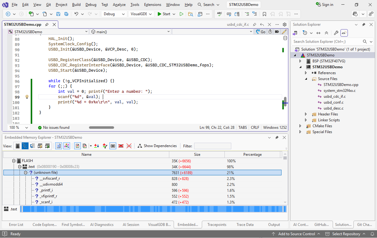
- Congratulations! If you see the output as in this example, you have created a fully functional USB device. Note how the FLASH footprint of the firmware has increased significantly after we started using printf(). Use the Embedded Memory Explorer to find which of the functions occupy most of the memory:
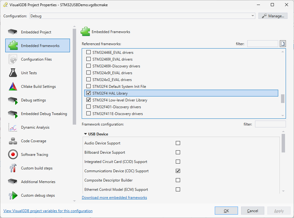
- You can reconfigure various frameworks used by your project (such as USB stack) via the Embedded Frameworks page of VisualGDB Project Properties: