Updating Firmware Over-the-Air on ESP8266
This tutorial shows how to update the firmware on your ESP8266 device using the firmware-over-the-air (FOTA) mechanism. Before you begin, install the latest VisualGDB and update your ESP8266 toolchain to 5.2.0-r7 or later.
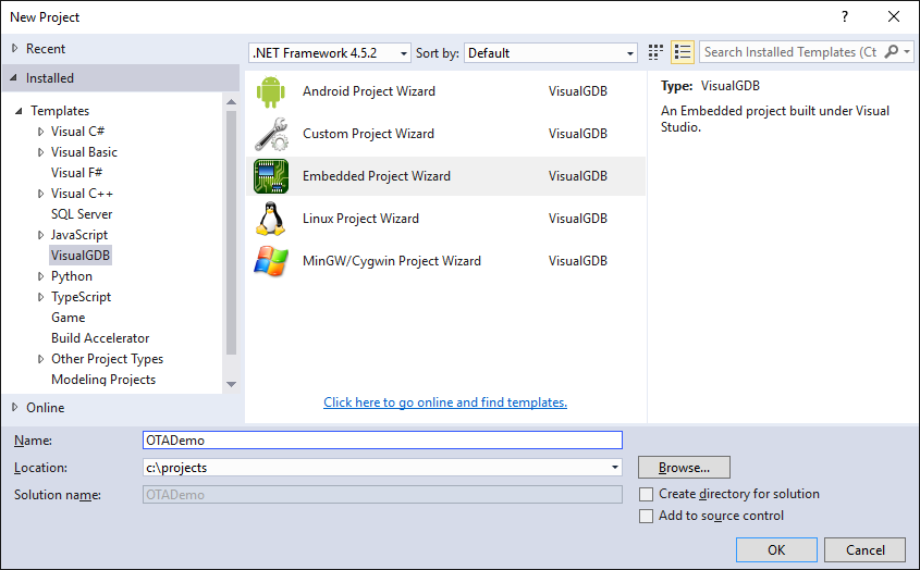
- Start Visual Studio and launch the VisualGDB Embedded Project Wizard:
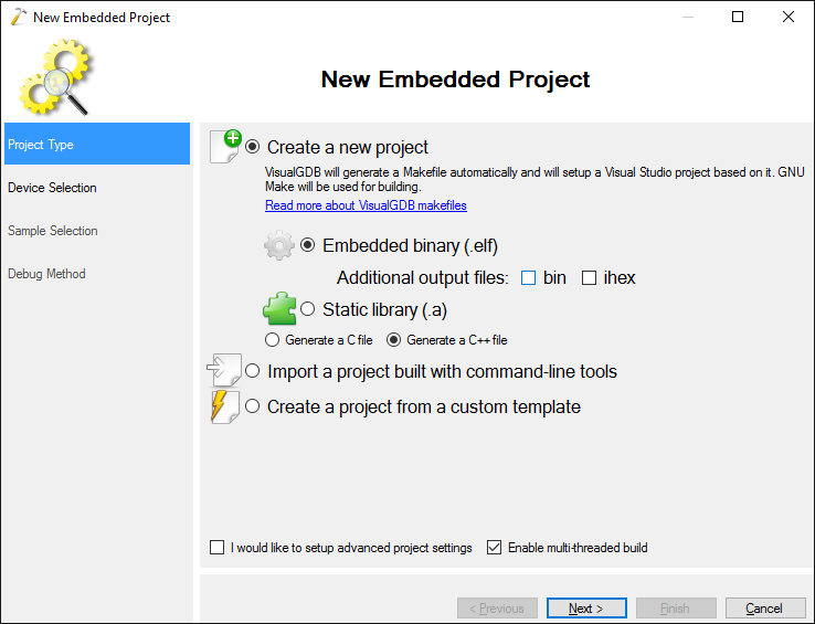
- Select “Create a new project -> Embedded binary” and uncheck the “.bin” flag as the ESP8266 toolchain uses its own binary format:
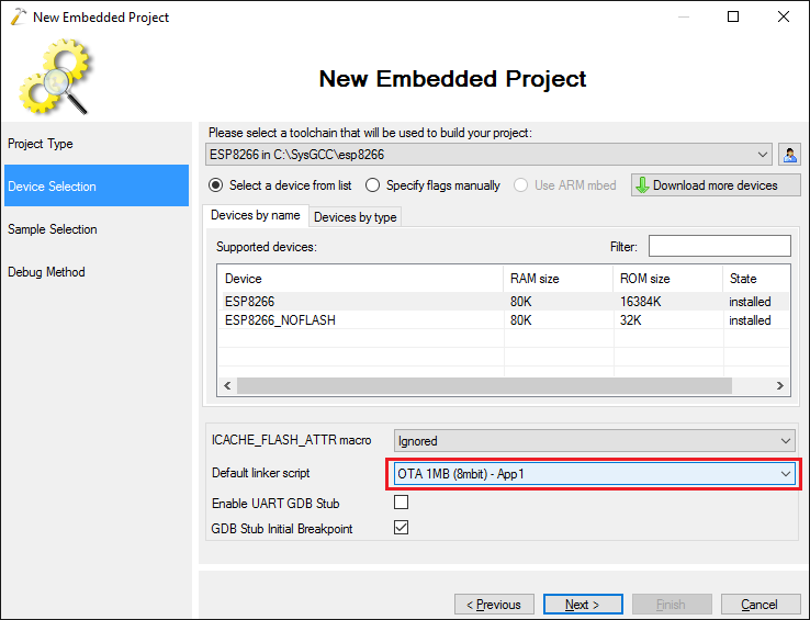
- On the next page select the ESP8266 toolchain and pick the device from the list. Then select “OTA 1MB – App1” as the default linker script. This will ensure that the firmware you build will be compatible with the over-the-air update mechanism. If your device has a smaller SPI FLASH chip, select OTA 512 KB instead of 1MB:
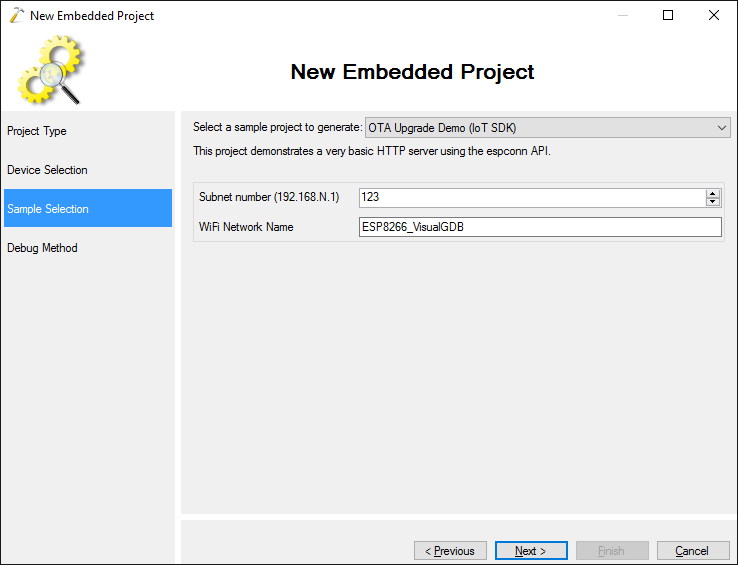
- Select the OTA Upgrade Demo sample from the list and press “Next”:
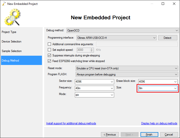
- On the Debug Settings page select the debug method that works with your hardware (you can follow this tutorial for details on JTAG debugging) and ensure that the FLASH size matches the one selected in the linker script selector (e.g. 1MB (8mbit) matches 8m in the debugger settings):
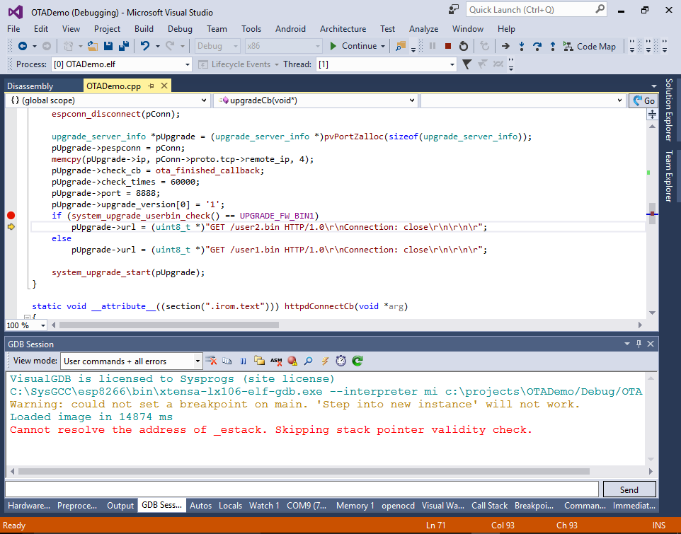
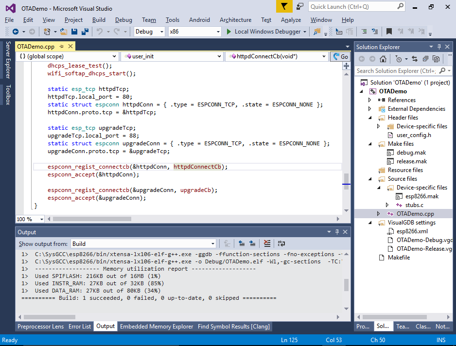
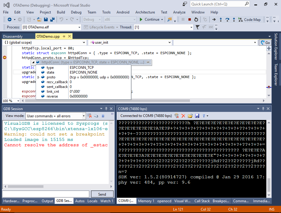
- Press “Finish” to create your project. Then build it with Ctrl-Shift-B. If you look at the user_init() function, you will see that it’s opening 2 ports for listening: port 80 that will be handled by httpdConnectCb() function and port 88 handled by upgradeCb():
- The upgradeCb() function that is invoked when anyone connects to port 88 begins the firmware update process using the API provided by the ESP8266 SDK. The firmware update process will connect to port 8888 on the host that connected to port 88, issue an HTTP GET request to either /user1.bin or /user2.bin and program it to the FLASH memory:
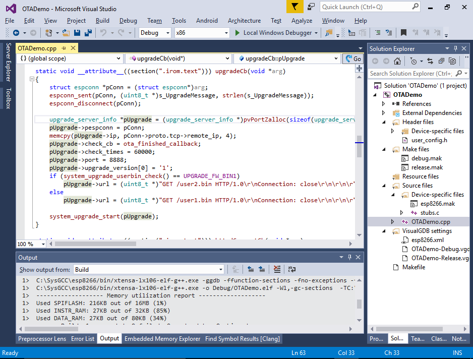 We will explain the role of user1 and user2 binaries later.
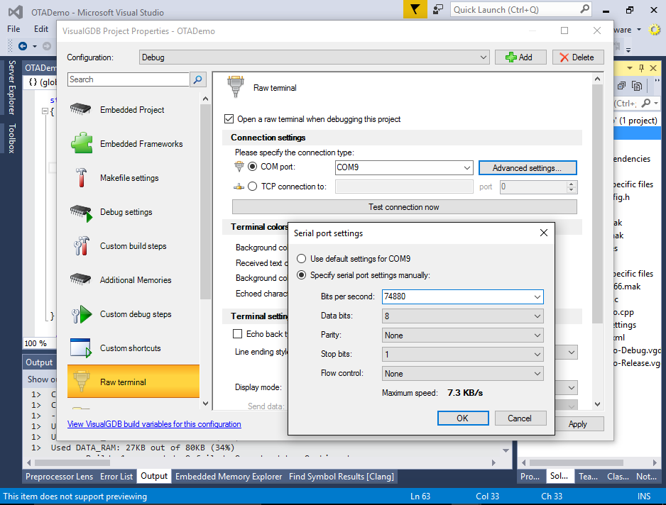
 - If you have connected the serial port on your ESP8266 to your computer, open VisualGDB Project Properties and configure the raw terminal to open on that port. Specify 74880 as the baud rate:
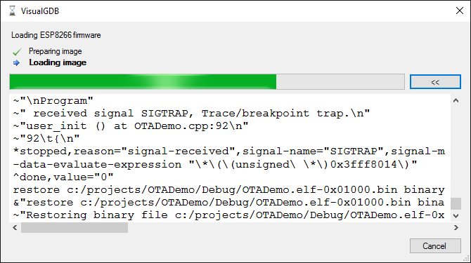
- Set a breakpoint in the initialization function and press F5 to begin debugging. VisualGDB will automatically program the FLASH memory with the OTA bootloader and your program binary and start debugging:
- One the breakpoint in user_init() hits you should be able to step through it and see how the initialization is performed:
- Note that VisualGDB had to bypass the OTA bootloader in order to make the startup function debuggable. If you now reset the device, you will see the bootloader output stating that it’s running the “user1” firmware from offset 0x1000:
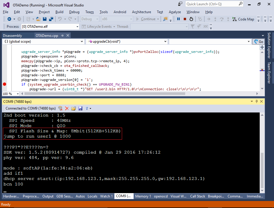 If instead of user1 you see user2, try erasing the FLASH memory of esp8266 using the esptool.py.
 - The over-the-air firmware update mechanism has a built-in protection against making the system unusable in case the connection drops during the update. Instead of overwriting the firmware the is currently running, it divides the FLASH memory into 2 regions and keeps 2 versions of the firmware in them. Those versions are called app1 and app2 respectively. If the firmware update is initiated while app1 is running, the update mechanism will overwrite the app2 and boot into it. Otherwise it will overwrite app1. If the update is incomplete or the CRC of the image does not match, the bootloader will ignore it and boot into the app that worked before.
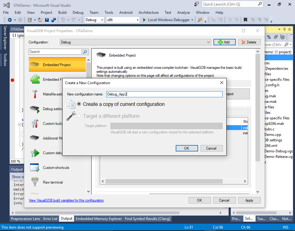
- The 2 versions of the firmware will reside in different locations inside the FLASH memory and hence need to be built with 2 different linker scripts. The configuration we built first uses the App1 linker script and is designed to run in the first half of the FLASH memory. We will now create a version to run in the second half. Open VisualGDB Project Properties and copy the current configuration into Debug_App2:
- Then go to the Makefile Settings page and change the linker script to eagle.app.v6.new.1024.app2.ld:
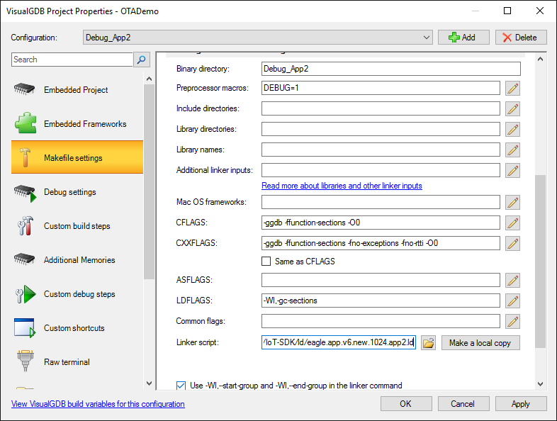 The “new” in the script name means the new bootloader format. The “1024” corresponds to the 1MB FLASH and “app2” places the app at the second 512KB slot of the 1MB memory.
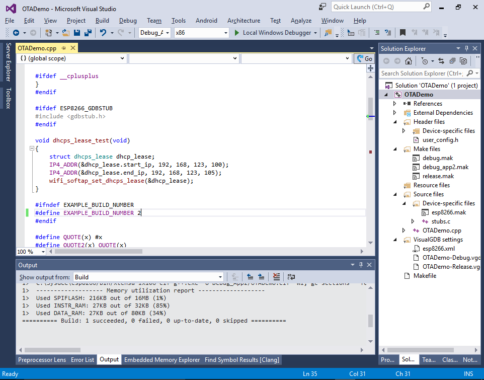
 - Change the EXAMPLE_BUILD_NUMBER to 2 in order to be able to distinguish the 2 versions of the firmware and build it with Ctrl-Shift-B:
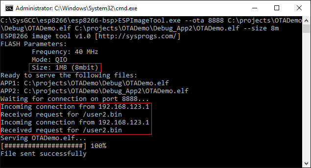
- Performing the over-the-air update involves converting the ELF files into a special binary format and sending it to the ESP8266 device over HTTP. The Sysprogs ESP8266 toolchain comes with a tool that does that automatically. Open the <SysGCC>\esp8266\esp8266-bsp directory and run the following command:
ESPImageTool --ota 8888 <ELF file built with App1 script> <ELF file built with App2 script> --size 8m
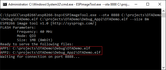 Double-check that the APP1 and APP2 are pointing at the correct ELF files. The image tool will automatically detect which of the ELF files corresponds to app1 and which one is app2 based on the addresses stored inside them. If one of the files was built with an incorrect linker script, it won’t appear in the APP1 or APP2 position.
Note that the FLASH memory size (1MB or 8 mbit in this example) should be the same when selecting the linker script, running ESPImageTool and debugging your application. It can be smaller than your actual SPI FLASH size, but must be the same in all the places. Otherwise the address where the image is loaded won’t match the address where the bootloader will expect it. - Now that the ESPImageTool is waiting for the connection, connect to the WiFi network created by ESP8266 and open the 192.168.123.1 page in the browser:
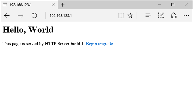 Note how it states that you are using build 1. Click the “begin update” link that will direct you to port 88 triggering the upgradeCb() function.
 - ESPImageTool will report that it received an incoming connection for user2.bin and automatically served the ELF file converting it to the ESP8266 binary format on-the-fly:
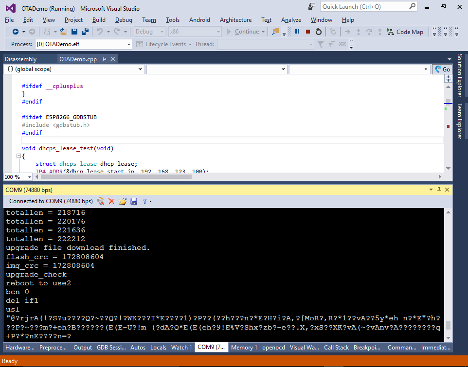
- The ESp8266 firmware update logic will print the progress about the upgrade operation to the serial port:
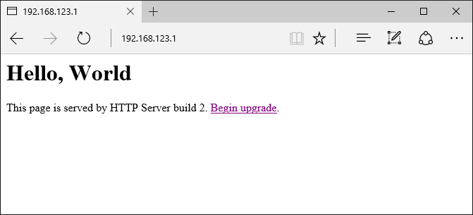
- If you now open 192.168.123.1 in your browser, you will see that it’s served by the build 2 of your app that corresponds to the Debug_App2 configuration:
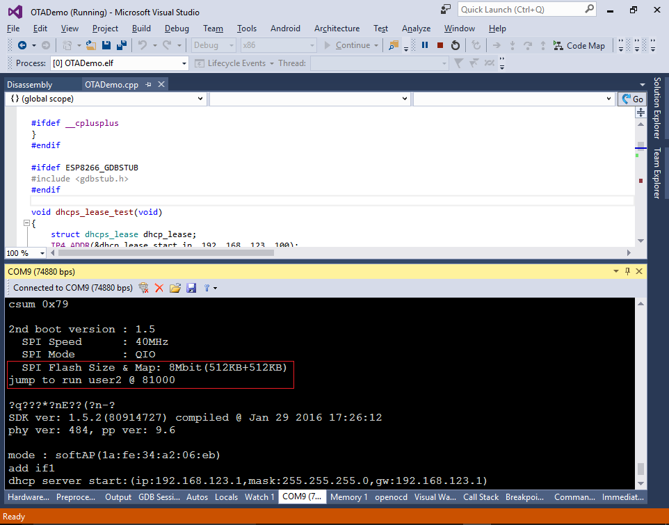
- If you reset the device now, the bootloader will show that it’s running the user2 application from offset 0x81000:
- You can start ESPImageTool again and click the “begin upgrade” link once more to see that now it requests the user1 image:
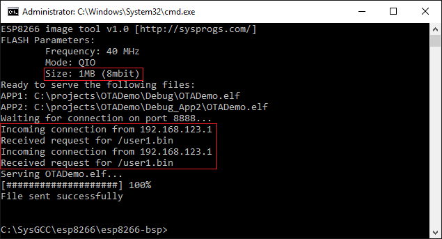 The build number shown in the browser will be changed back to 1 as well (unless you rebuilt the Debug configuration with the increased build number).
 - You can see how the firmware chooses between /user1.bin and /user2.bin based on the return value of system_upgrade_userbin_check() that tells it which version of the library is currently running: