Connecting a Rotary Encoder to ESP32 using AI
In this tutorial we will use AI edits to modify the ESP32 HTTP server example to handle a rotary encoder and show its real-time position on the main page.
We will use AI edits to quickly do trivial work (e.g. translate encoder signals to rotation value), while still keeping full control over the code quality. Before you begin, install VisualGDB 6.1 or later.
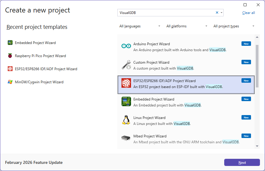
- Start Visual Studio and launch the ESP-IDF project wizard:
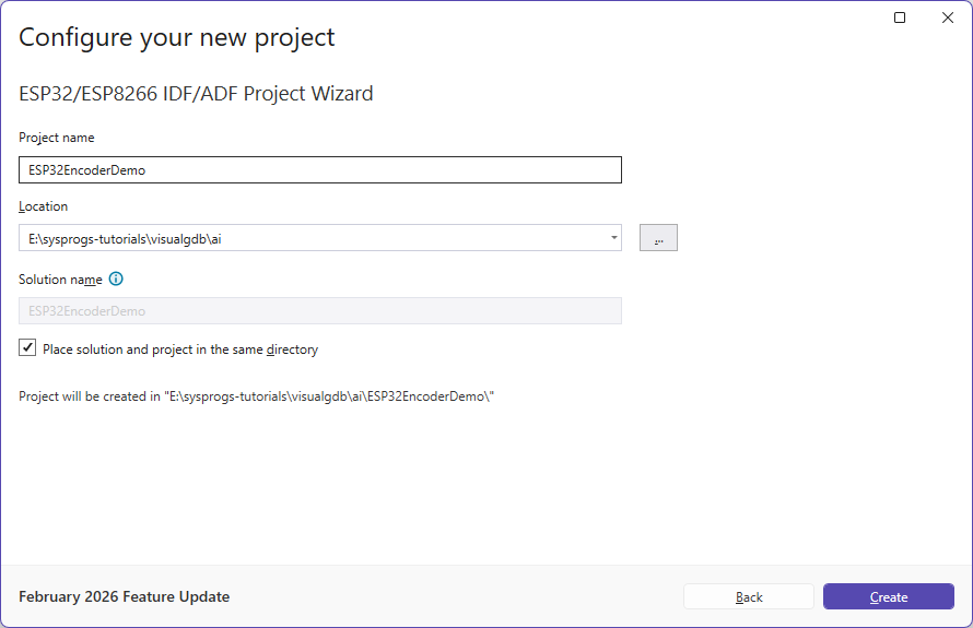
- Enter the name and location where you would like to put the project:
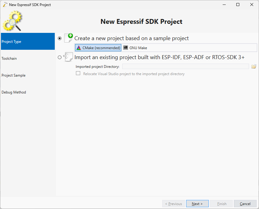
- Proceed with the default build system settings:
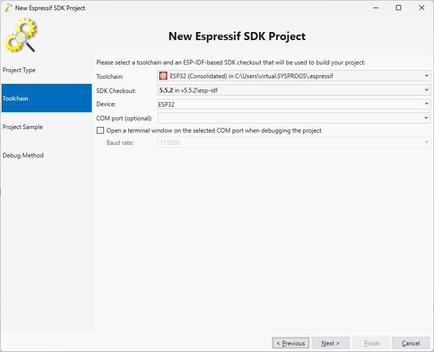
- Select the consolidated ESP-IDF toolchain and ESP-IDF version you would like to use:
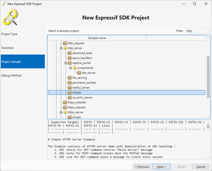
- On the Project Sample selection page select http_server -> simple:
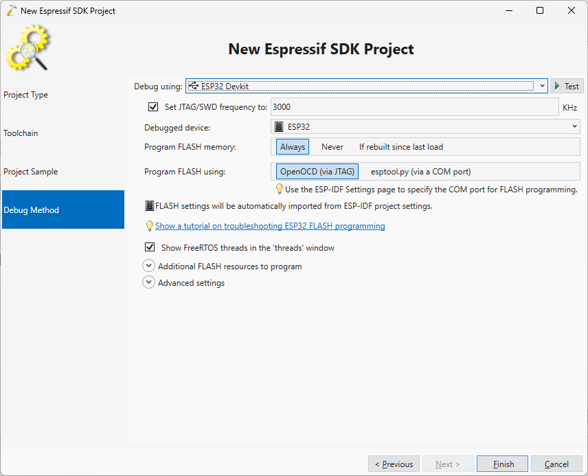
- On the last page of the wizard, pick the debug settings that work with your device:
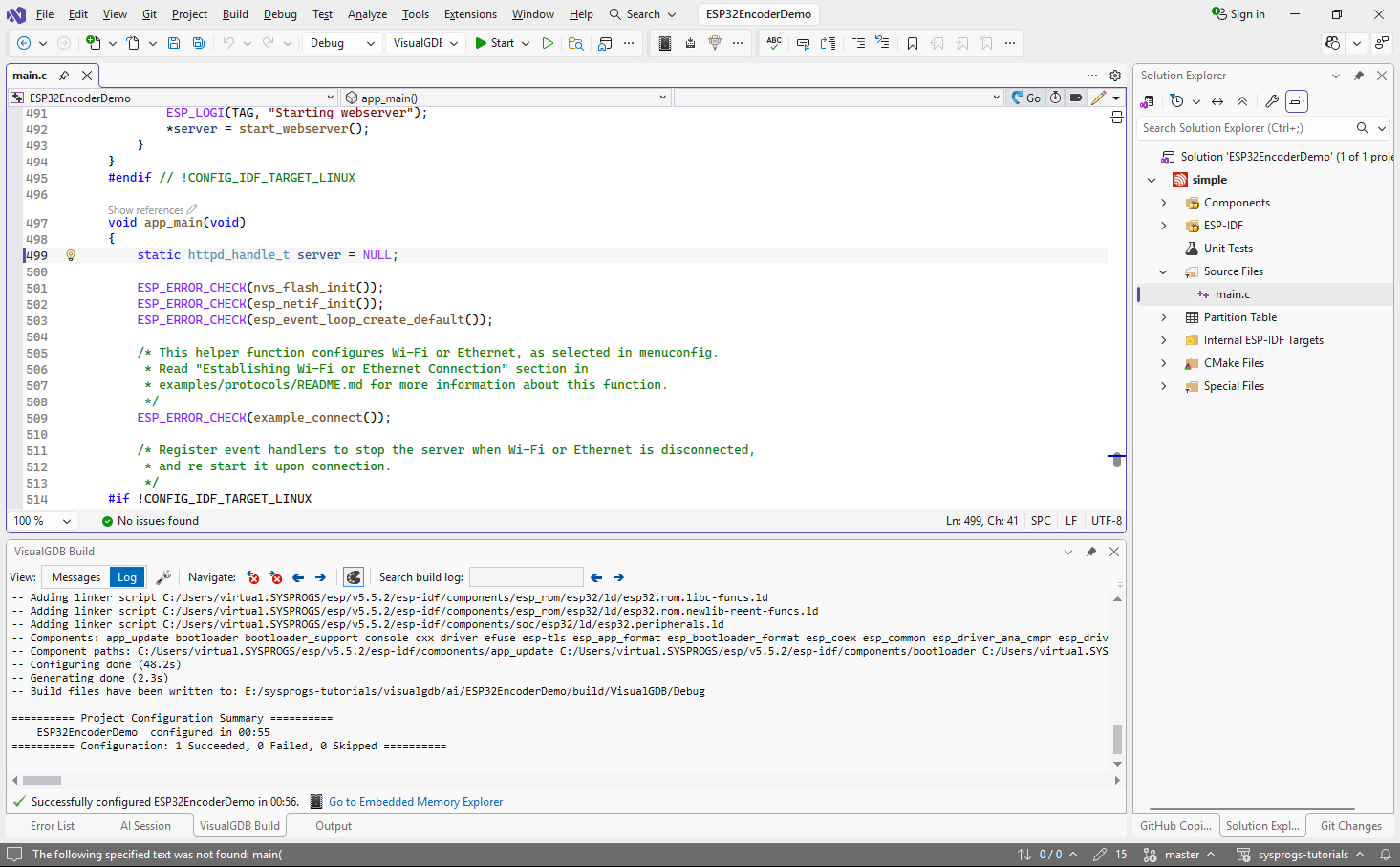
- Press “Finish” to create the project. Make sure it gets configured correctly:
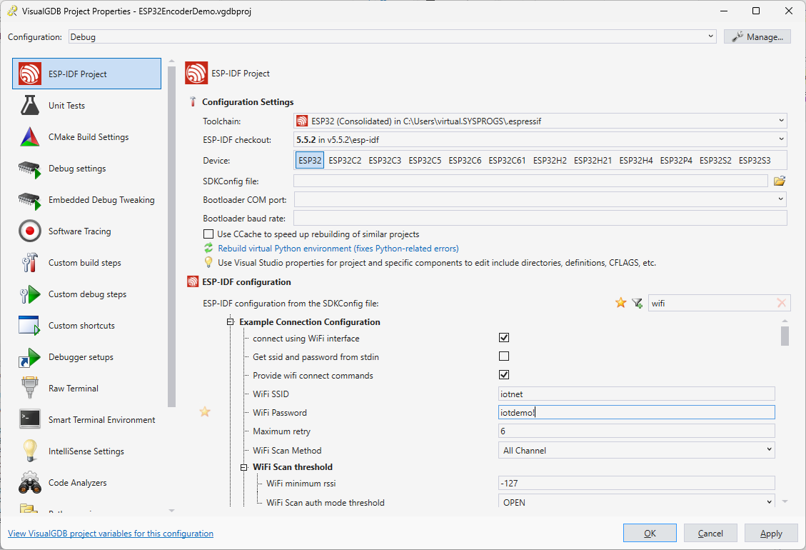
- Before adding any changes, we will verify that the original project can connect to the Wi-Fi network. Open VisualGDB Project Properties and configure the Wi-Fi SSID/Password parameters:
- Press F5 to build the project and start debugging it. Once it loads and connects to the Wi-Fi network, try opening http://<IP ADDRESS>/ (not https) in the browser and make sure it shows the default message:
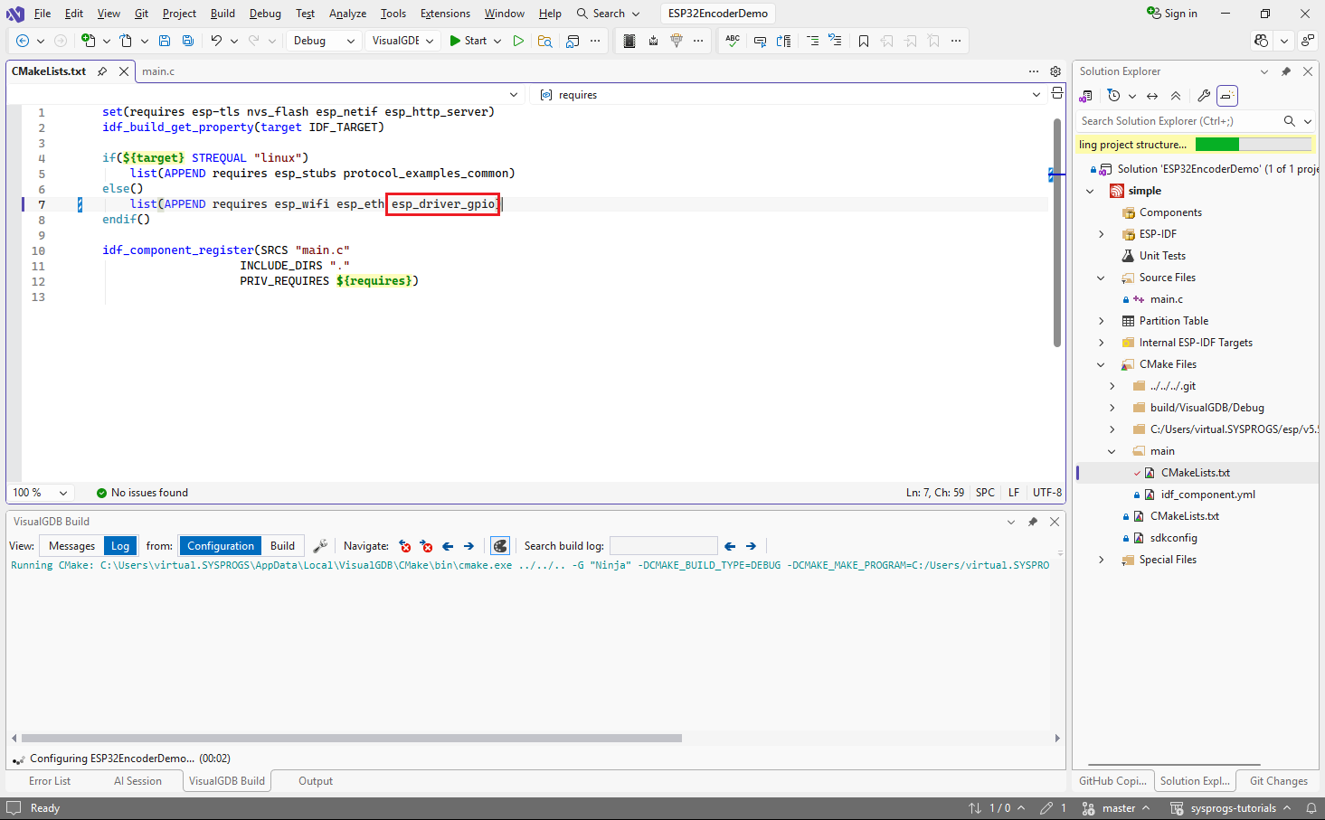
- We will use the GPIO driver to interface with the rotary encoder, so make sure it is referenced from the main component’s CMakeLists.txt file:
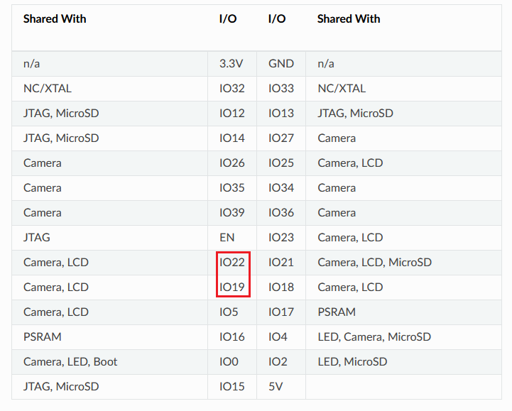
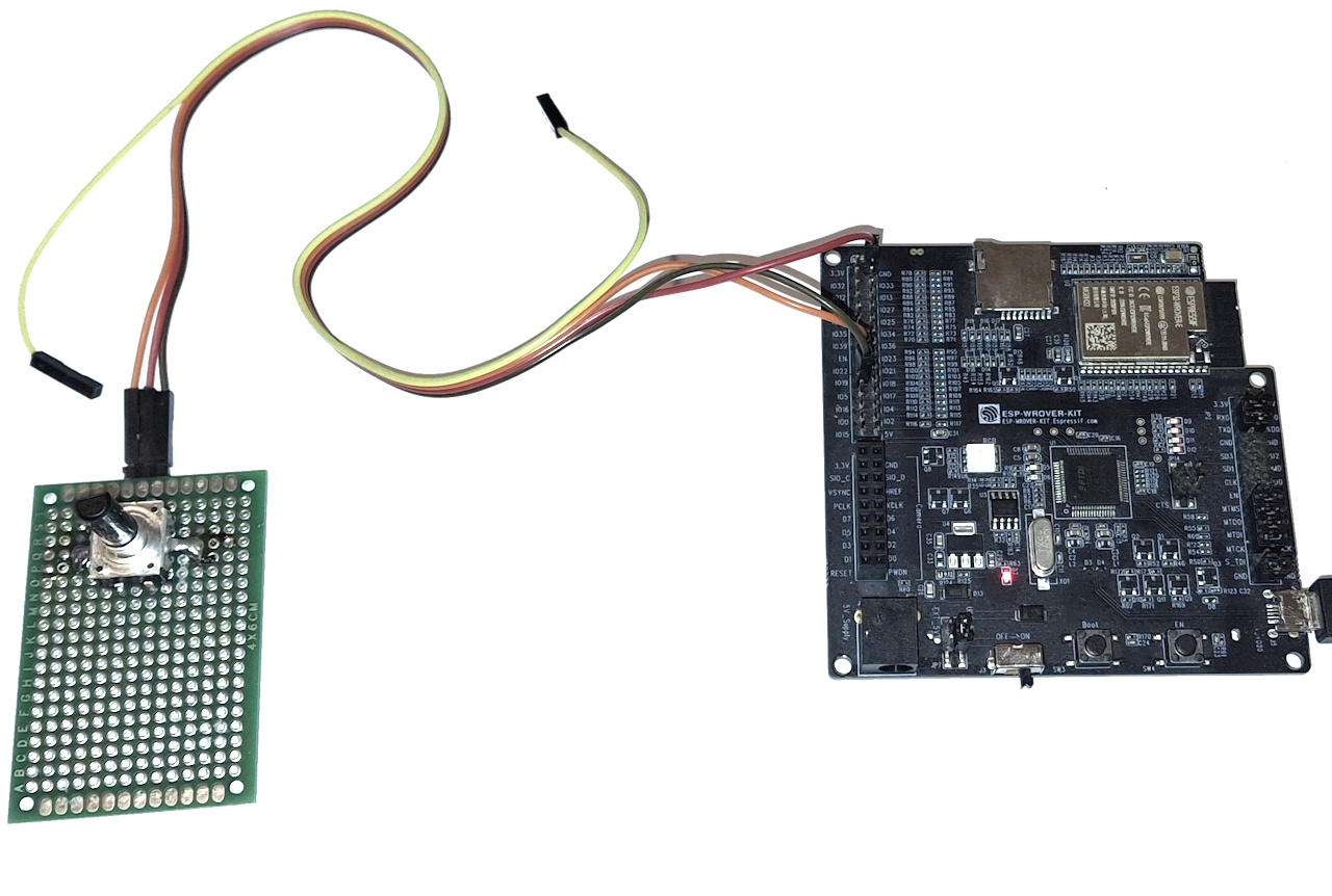
- In this tutorial we will use the ESP32-WROVER kit board, that uses most GPIO pins for existing peripherals. As we are not using on-board LCD display in this tutorial, we will borrow the GPIO19 and GPIO22 pins for use with the encoder:
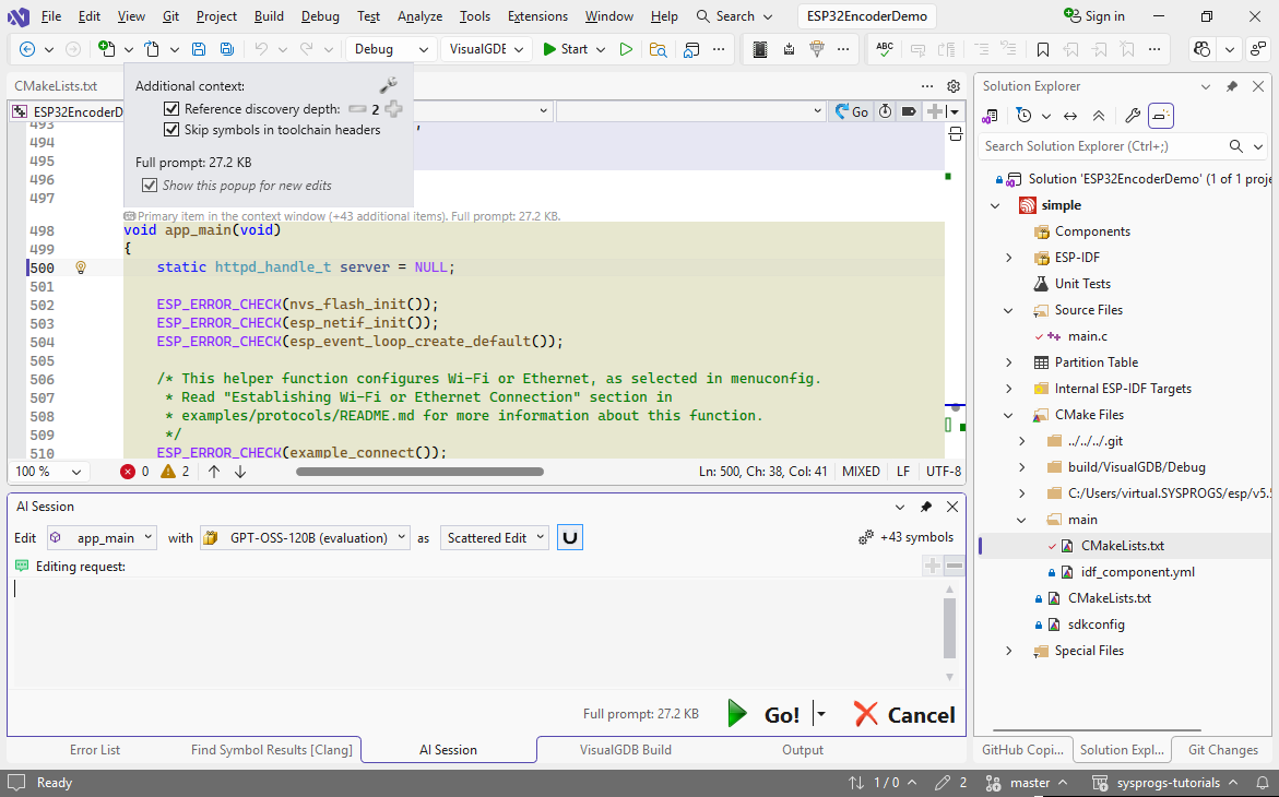
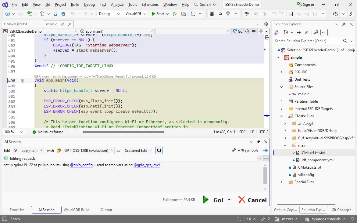
- To start using them, we would need to first configure them as inputs using the ESP-IDF GPIO functions in main(). Instead of doing it by hand, we will use VisualGDB’s symbol-level edits to quickly update the code based on a minimal prompt. Click the edit button in the CodeJumps link above main() to begin the edit:
- Use the following prompt:
setup gpio#19+22 as pullup inputs using @gpio_config + read to tmp vars using @gpio_get_level
- VisualGDB will automatically pick main() and all declarations used by it, will pass it to the model together with the symbols mentioned in the prompt. This works much more efficiently than passing entire files at a time, so it only takes a few seconds to get the edits done:
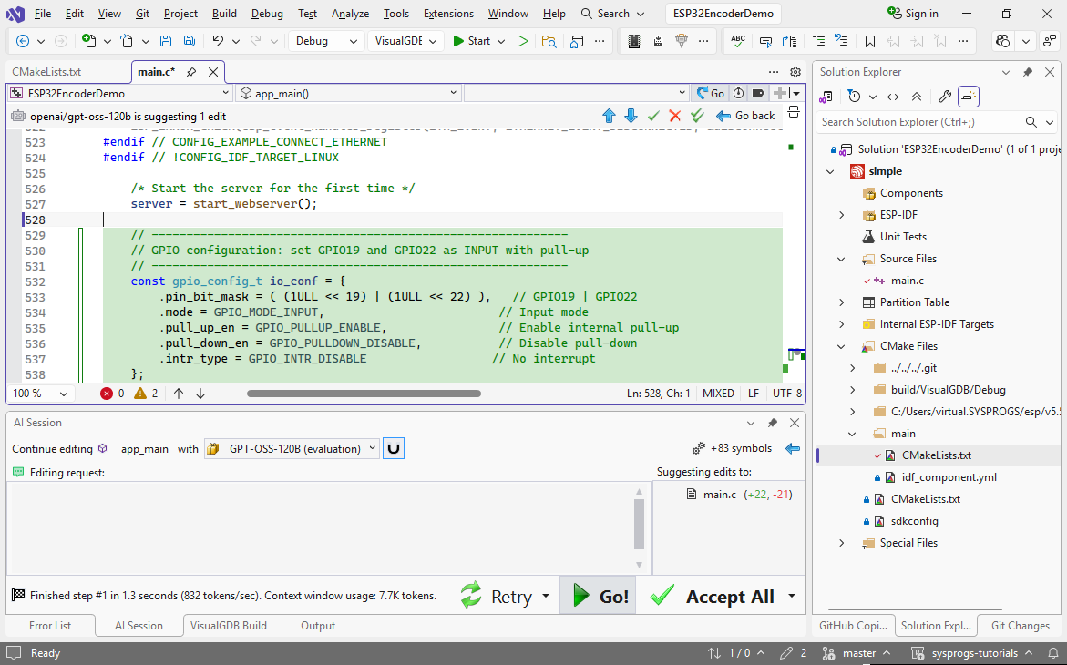 Note that VisualGDB automatically passes the definitions of gpio_config_t, gpio_get_level(), etc. to the model, so it will work equally well with frameworks that are less known than ESP-IDF.
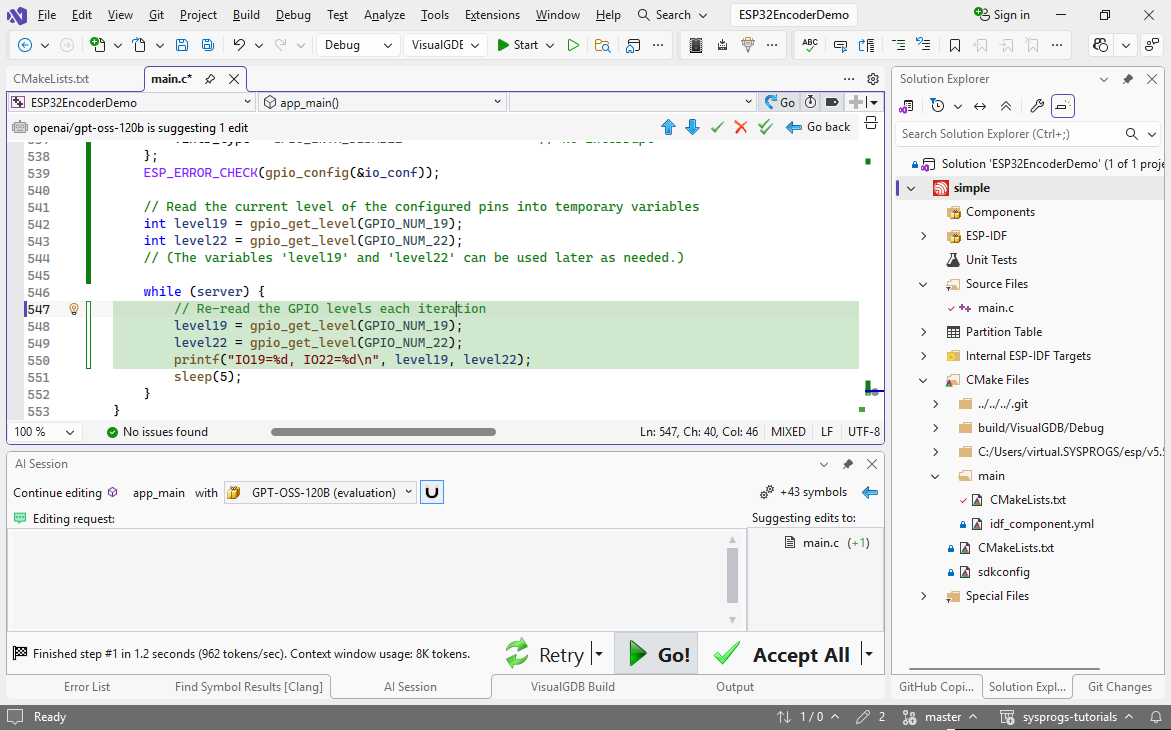
 - Now we will ask the AI to read and print the GPIO values in a loop. Use this prompt on main():
in loop, print IO19=..,..
This will update the while() loop in the end to print the GPIO values:
- Build the code and start another debugging session. Once the firmware starts, connect to the board’s COM port via a context menu in Solution Explorer and make sure it prints the values:
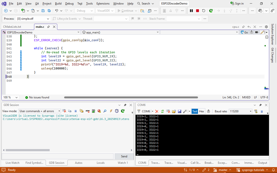
- You can now connect the encoder to the pins on the board and try turning it. The IO19 and IO22 values should change as your rotate the knob:
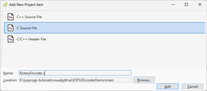
- Now we will restructure the code to have all encoder-related logic in a single source file. It will use the RotaryEncoder struct to store the encoder configuration and state, and will have RotaryEncoder_XXX() functions for various functionality. Add a new file called RotaryEncoder.c the project:
- Similarly, add RotaryEncoder.h containing an empty RotaryEncoder struct:
#pragma once

struct RotaryEncoder
{
};
Make sure RotaryEncoder.h is included from main.c and RotaryEncoder.c.
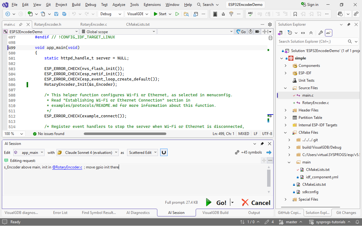
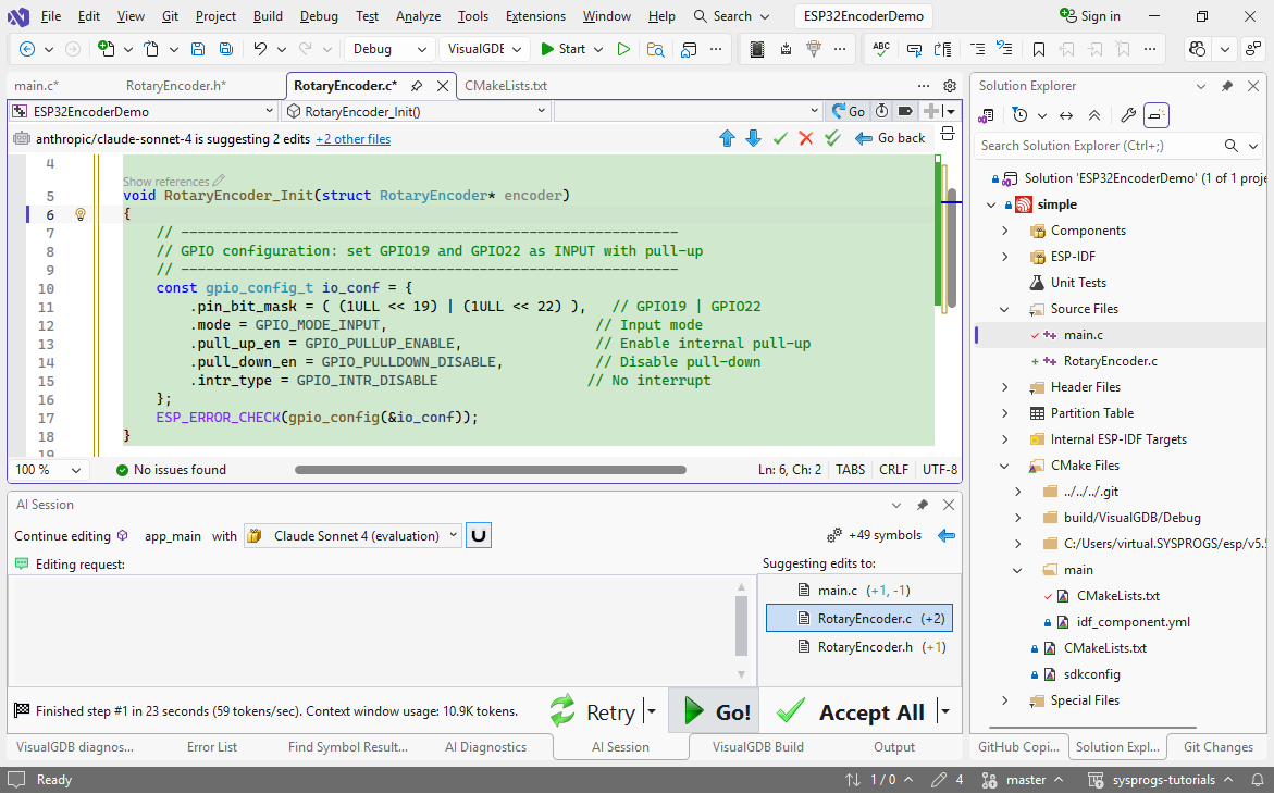
- Now we can use the AI to move initialization code to our new encoder driver. Add the “RotaryEncoderInit(&s_Encoder)” call to main and use the following prompt:
s_Encoder above main, init in @RotaryEncoder.c; move gpio init there
- This is sufficient for the AI to create the missing declarations, definitions, and move the current initialization code where it belongs:
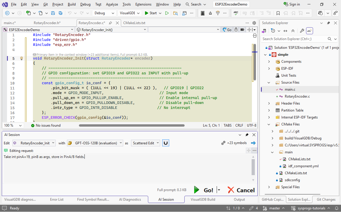
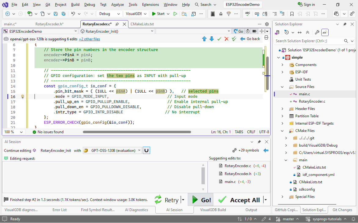
- Note that the init function still has hardcoded GPIO19 and GPIO22 pins. To make the driver more flexible, we should instead pass them as arguments and store in RotaryEncoder’s fields. Use this prompt:
Take int pinA=19, pinB as args, store in PinA/B fields
- This will quickly add the fields to the struct, add initialization code and update the call in main():
- Now we will add an interrupt handler that will get invoked whenever the signal on either of the pins changes. Use this prompt on the init function:
Add edge-triggered interrupt handler (static RotaryEncoder_HandleGPIOInterrupt) on both pins.
Use @gpio_install_isr_service , @gpio_isr_handler_add
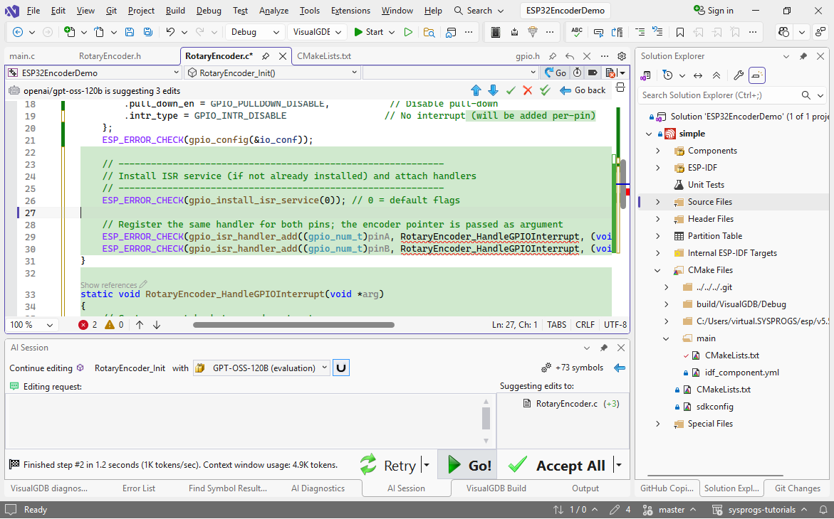 In this example we used a very small, but fast model, that generated the correct function, but did not make a forward declaration. You can fix it by moving the function manually, or by using a larger model to generate code.
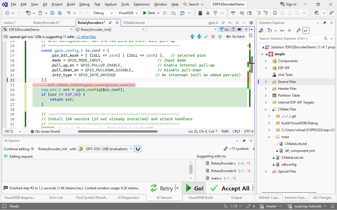
 - Note that the AI used the ESP_ERROR_CHECK macro for error handling, because it was used in the original main() function. In our encoder driver, we want to return an error code instead. Use the “if/return instead of ESP_ERROR_CHECK” prompt to quickly change the relevant parts:
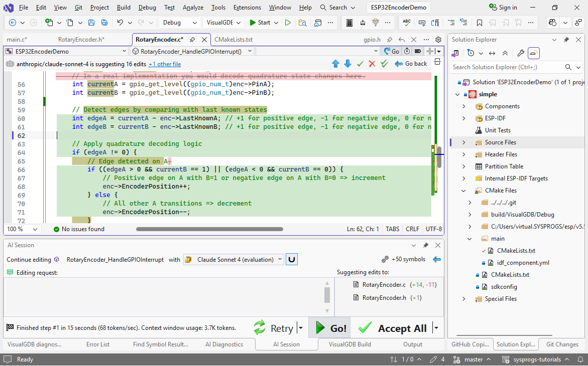
- Now we will use AI to actually analyze the rising/falling edges on the encoder signals, and update the count. The logic for it is very straight-forward if you look at the state diagram from Wikipedia, however it requires several similar checks. AI can very easily write them based on a fairly concise summary:
Maintain EncoderPosition field & LastKnownA/B
Update like this:

Positive edge on A with B=1 or negative with B=0 => increment
Positive B with !A or negative B with A => also
Others => decrement
As the edits are concentrated in a single relatively small function, even large models will manage them quite fast:
- Now let’s manually update the main loop to print the encoder position and try it out:
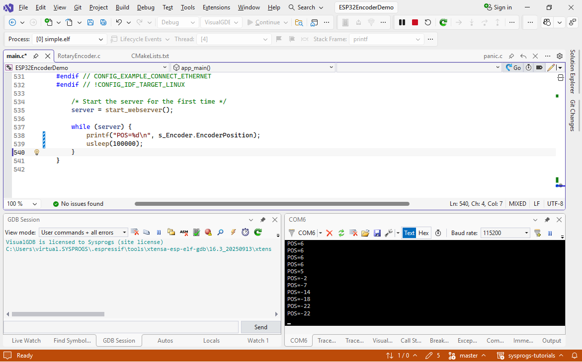 If you try rotating the encoder now, you should see the position update in real time.
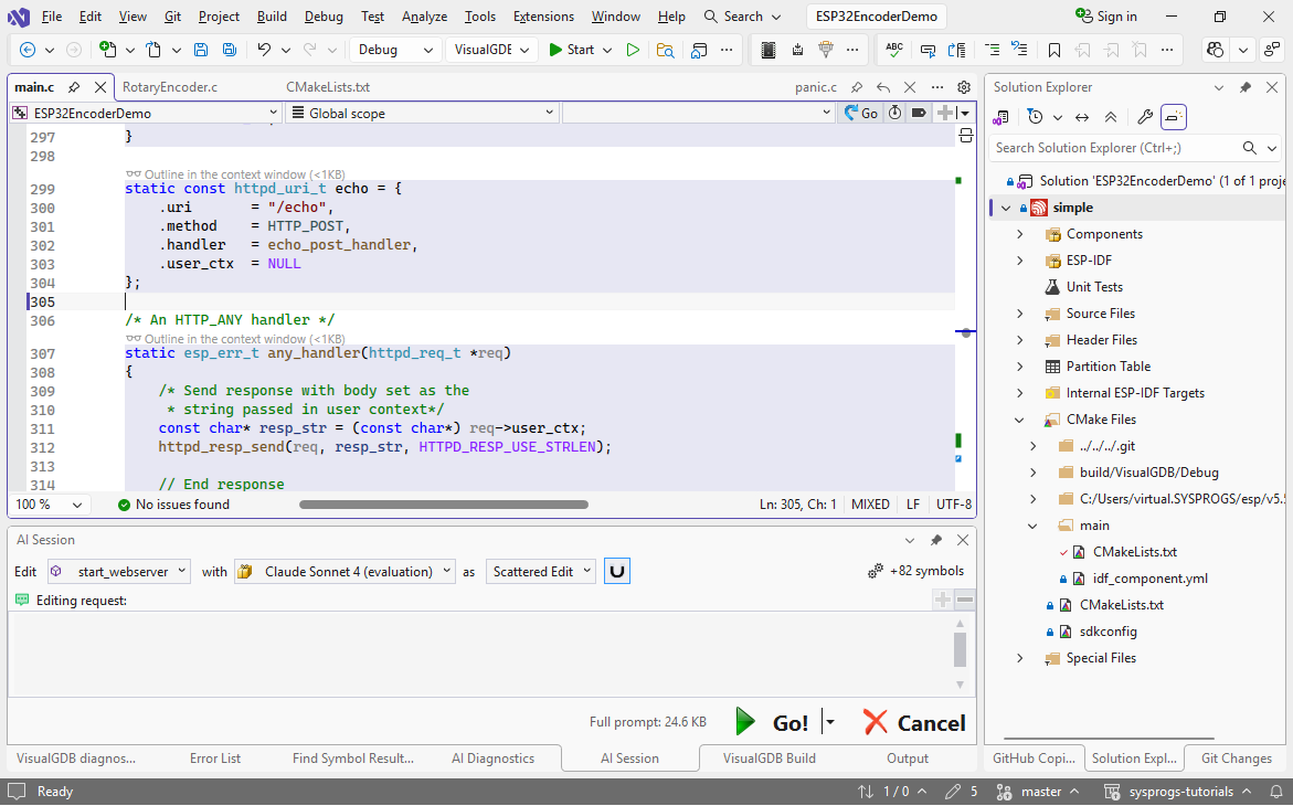
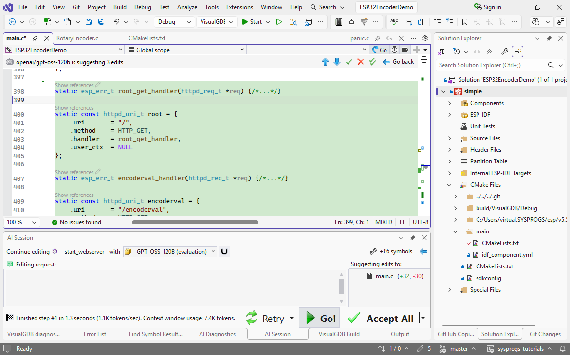
 - The last step would be to update the HTTP server to show the encoder position. We will do it by adding a root page with a simple field, and an /encoderval API returning the value. The example project registers handlers for various pages in the start_webserver() function. AI can very easily add more similar pages there, along with the necessary structures. Begin editing start_webserver():
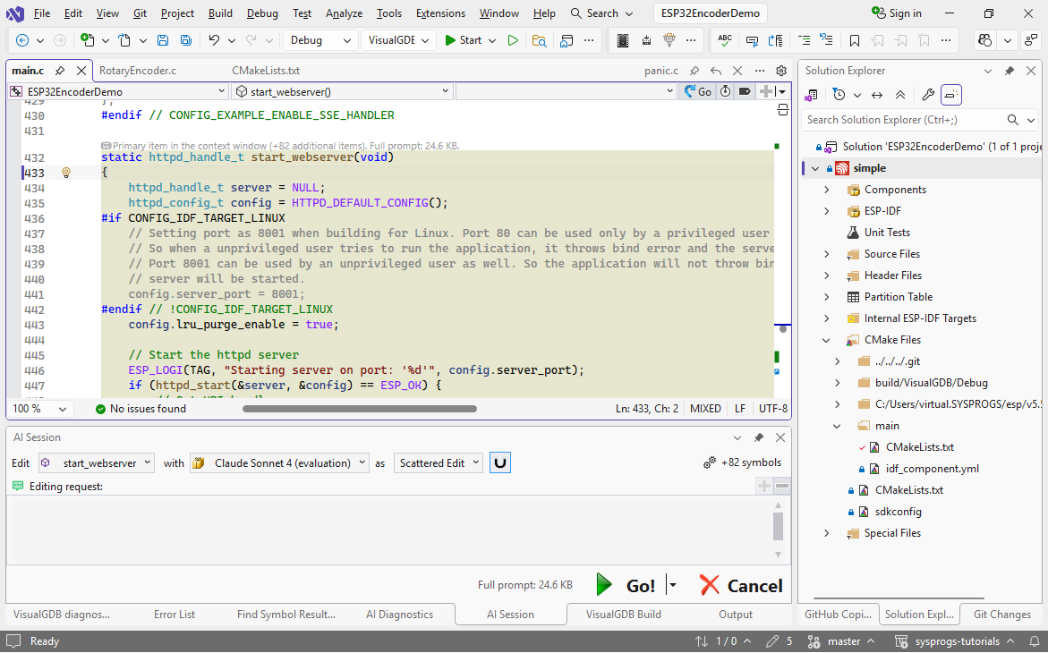
- Note how VisualGDB highlighted the symbols that were used by start_webserver(). They will be automatically included in the context window, so AI be able to use them for reference:
- Use this prompt:
register handlers for / (root) and /encoderval
 This will quickly copy the layout of the existing handlers, adding the two additional ones.
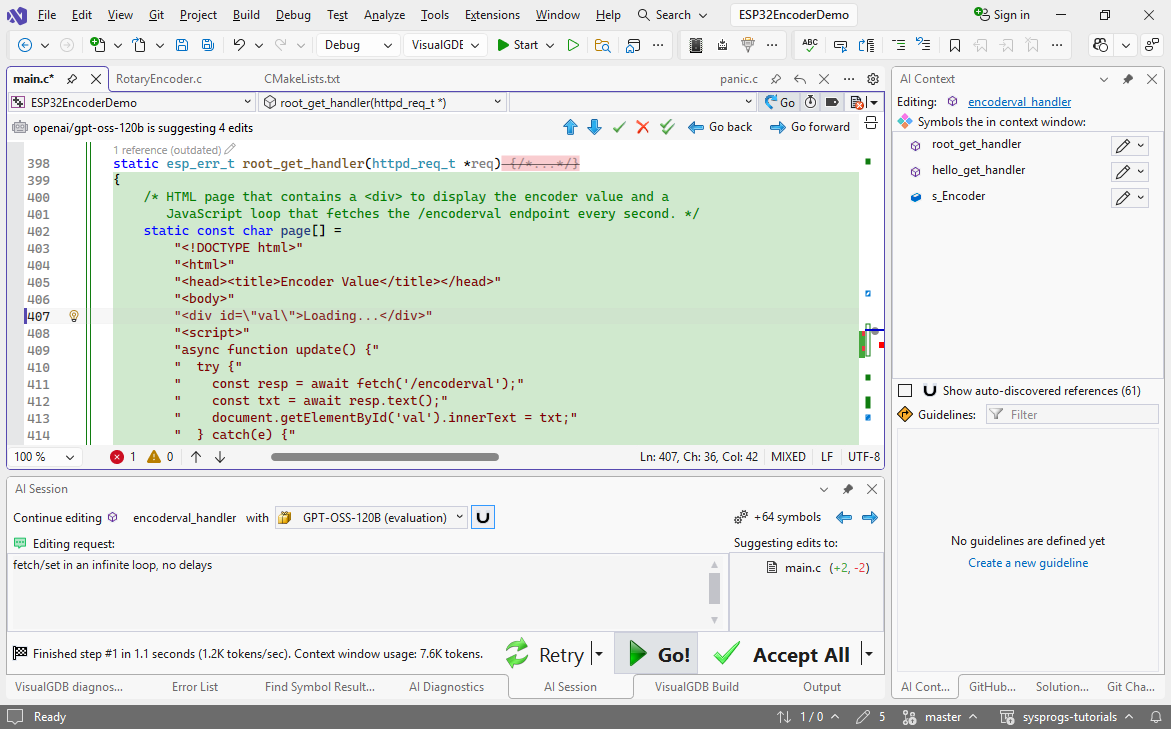
 - Select both handlers for editing and use this prompt to create basic implementations:
Implement handlers: encoderval return value from @s_Encoder ; root - page with a div and a script loading /encoderval in an infinite loop with await
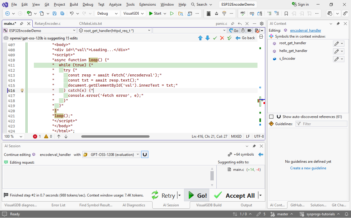
- In this example, the model decided to call the update function instead of having an infinite loop with awaits. Using “fetch/set in an infinite loop, no delays” as a refinement prompt quickly changes the layout to the fastest possible:
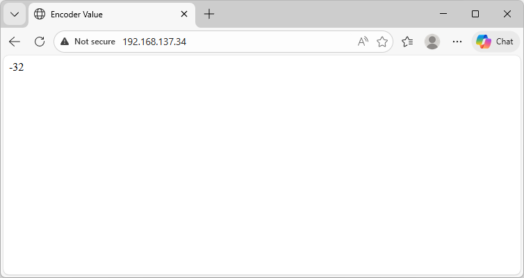
- If you run the application now and open the device IP address in the browser, you will see the encoder value being updated in real time: