Developing FreeRTOS Applications for Kinetis Devices
This tutorial shows how to develop embedded applications based on FreeRTOS for the Kinetis devices. We will create a basic multi-threaded application and run it on the FRDM-KL25Z board. Before you begin, install VisualGDB 5.0 or later.
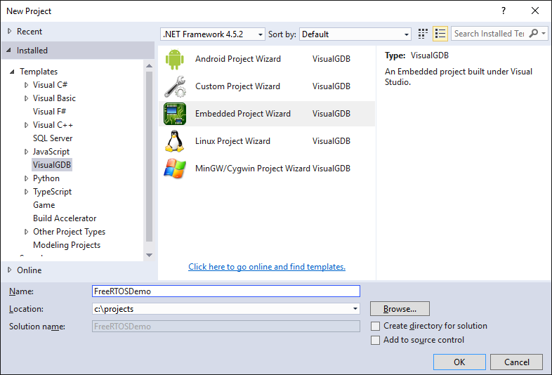
- Start Visual Studio and open the VisualGDB Embedded Project Wizard:
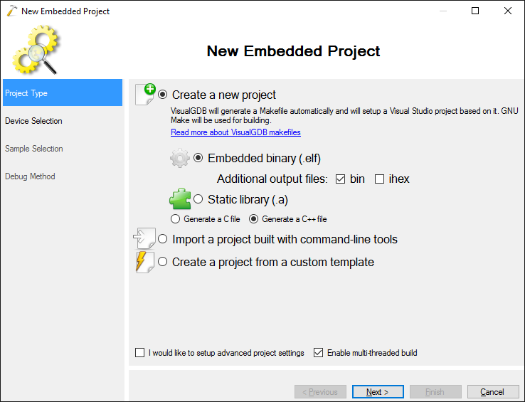
- Select “Create a new project -> Embedded Binary”:
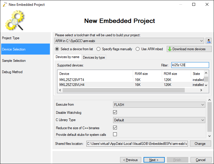
- Select the ARM toolchain and choose your Kinetis device. If you don’t have the Kinetis KSDK package installed, VisualGDB will download and install it automatically once you select the device. In this tutorial we will use the MKL25Z128VLH4 device that is installed on the FRDM-KL25Z board:
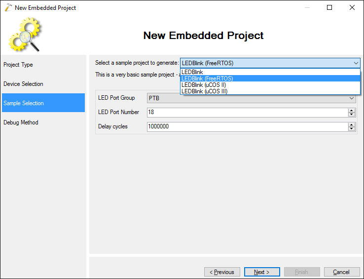
- On the sample selection page select the LEDBlink (FreeRTOS) sample and proceed with the default settings:
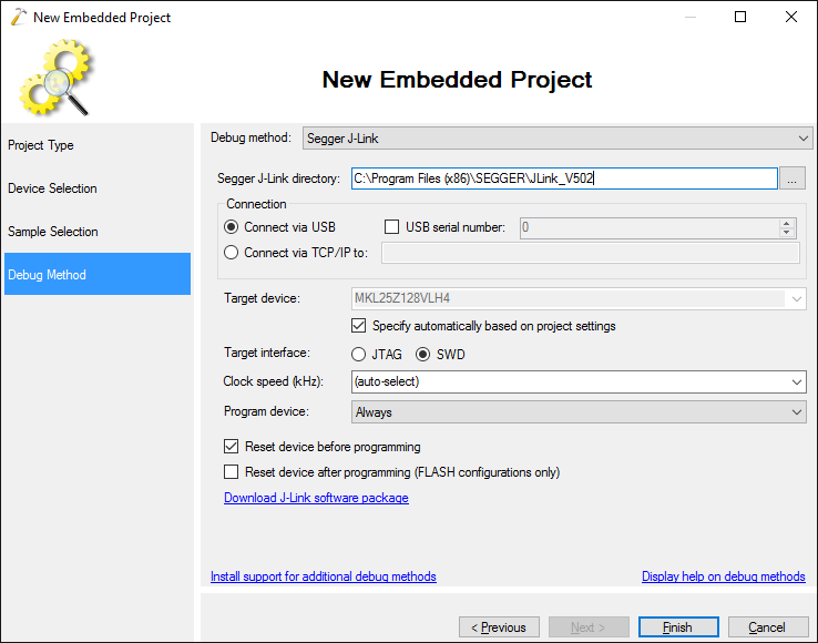
- On the Debug Method page select the Segger J-Link method and follow the instructions described in this tutorial to download the Segger J-Link firmware into the on-board OpenSDA programmer:
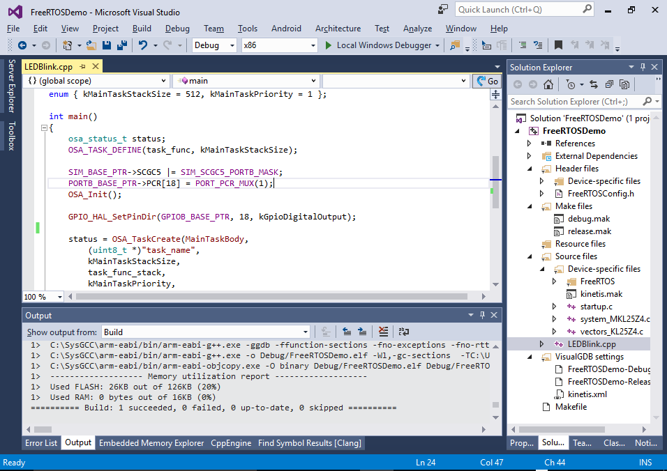
- Press “Finish” to generate your project. Build it via Build->Build Solution:
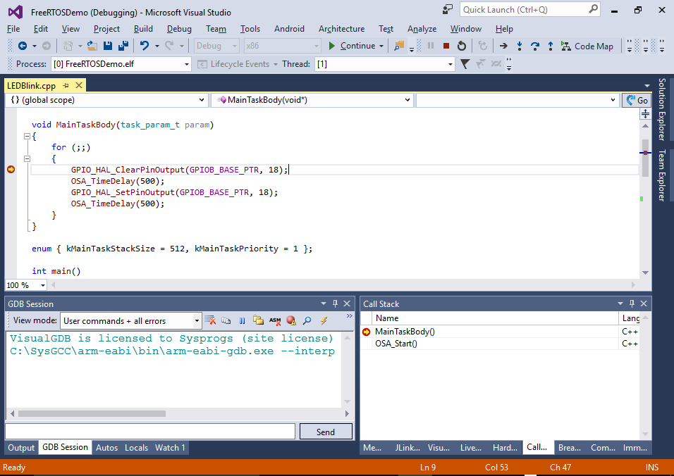
- The created project contains just one thread that will blink the red LED on the board that is connected to port B18. Before we begin modifying it, press F5 to program it and verify that the LED actually blinks. Then set a breakpoint in MainTaskBody() and try stepping through it:
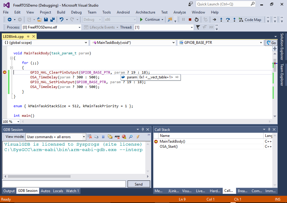
- Now we will modify the source code to have 2 threads instead of one. First of all replace the MainTaskBody() method to change the output of either port 18 (red LED) or port 19 (green LED) depending on the argument value and use different periods for these 2 LED channels:
void MainTaskBody(task_param_t param)
{
    for (;;)
    {
        GPIO_HAL_ClearPinOutput(GPIOB_BASE_PTR, param ? 19 : 18);
        OSA_TimeDelay(param ? 300 : 500);
        GPIO_HAL_SetPinOutput(GPIOB_BASE_PTR, param ? 19 : 18);
        OSA_TimeDelay(param ? 300 : 500);
    }
}
- Then add initialization for port 19 similar to port 18 to the main() function:
    PORTB_BASE_PTR->PCR[18] = PORT_PCR_MUX(1);
    PORTB_BASE_PTR->PCR[19] = PORT_PCR_MUX(1);
    OSA_Init();

    GPIO_HAL_SetPinDir(GPIOB_BASE_PTR, 18, kGpioDigitalOutput);
    GPIO_HAL_SetPinDir(GPIOB_BASE_PTR, 19, kGpioDigitalOutput);
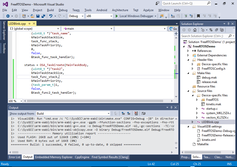
- Finally create another task in the main() function that will call the same MainTaskBody() method with an argument of 1 so that it will control channel 19 instead of 18:
    OSA_TASK_DEFINE(task_func2, kMainTaskStackSize);
    status = OSA_TaskCreate(MainTaskBody,
        (uint8_t *)"task2",
        kMainTaskStackSize,
        task_func_stack,
        kMainTaskPriority,
        (task_param_t)1,
        false,
        &task_func2_task_handler);
- Press F5 to build the project and ensure that the RGB LED color alternates between red, green and yellow (red + green). Then set a breakpoint in MainTaskBody() and see how it sometimes runs within a thread where param is 0 and sometimes in a thread where param is 1:
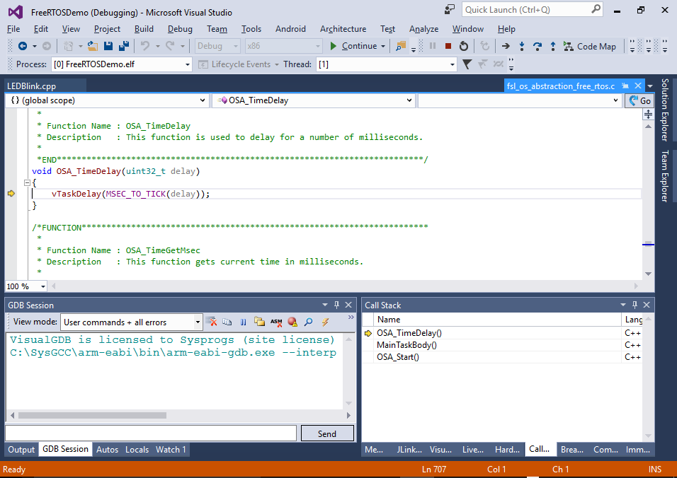
- Note that instead of calling the FreeRTOS functions directly the code calls OS Abstraction Layer functions like OSA_TimeDelay(). If you step into one of those, you will see that they simply call the FreeRTOS functions:
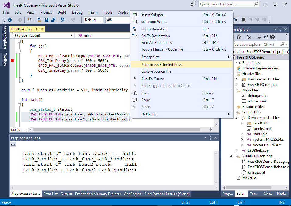
- The Kinetis abstraction layer heavily relies on the preprocessor macros like OSA_TASK_DEFINE(). You can quickly see the actual code behind those macros by right-clicking on the lines containing them and selecting “Preprocess selected lines”:
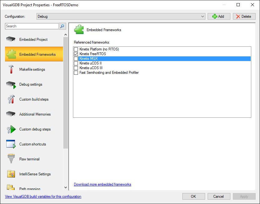
- You can manage the frameworks referenced by the project (such as FreeRTOS) via the Embedded Frameworks page of VisualGDB Project Properties: