Creating a FreeRTOS-based WiFi HTTP server for ESP8266
This tutorial shows how to create a FreeRTOS-based HTTP server with the ESP8266 chip. Unlike the single-threaded IoT SDK that requires writing code in the form of event handlers, the newer RTOS SDK allows creating threads that will be automatically scheduled by the FreeRTOS scheduler and can utilize common patterns like “wait for more incoming data to arrive”. We will create a basic WiFi HTTP server and modify it to allow controlling the on-board LED and the relay by pressing buttons in the browser.
Before you begin, follow the ESP8266 OpenOCD tutorial to get started with JTAG debugging for your ESP8266 board.
- Start Visual Studio and launch the VisualGDB Embedded Project Wizard:
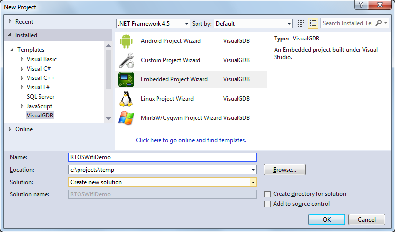
- Select “New project” => “Embedded Binray” and uncheck the “bin” file checkbox:
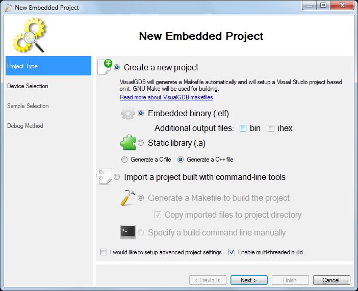
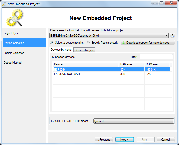
- Select the ESP8266 toolchain and pick the normal ESP8266 device. As the RTOS code is relatively large, it won’t entirely fit in the RAM and the “NOFLASH” option won’t work:
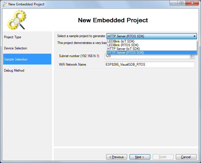
- On the sample selection page pick the HTTP Server (RTOS SDK) sample:
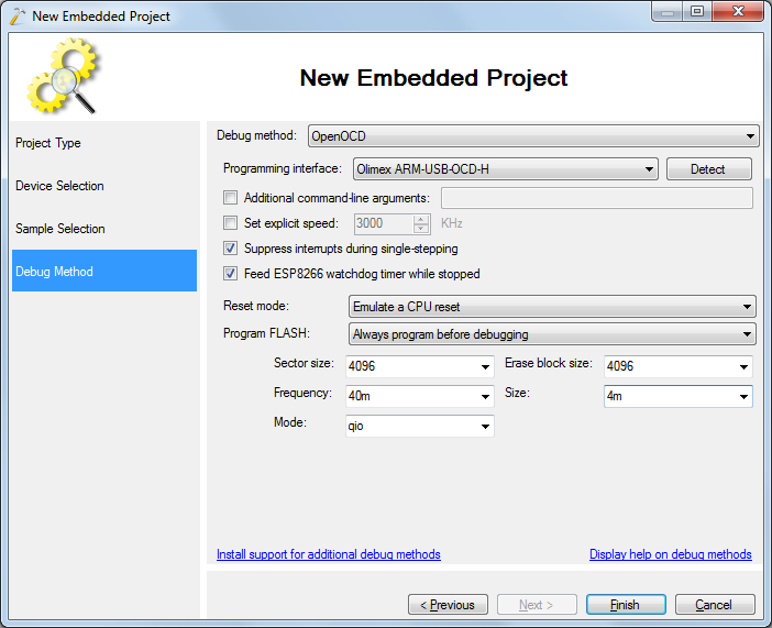
- Finally choose the debugging settings that worked for the basic blinking LED program when you were trying the OpenOCD tutorial:
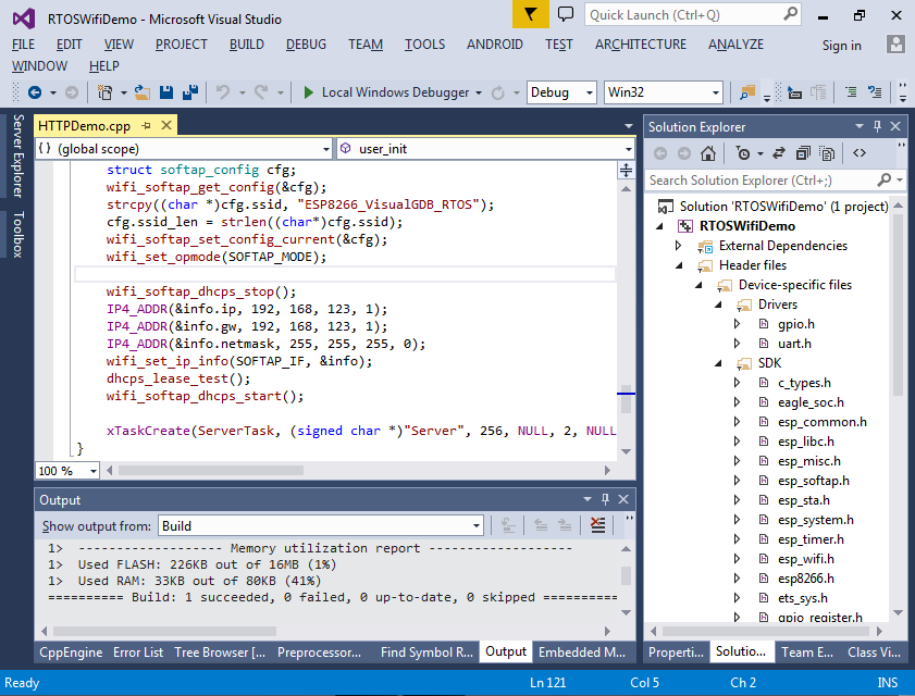
- Press Finish to create the project and build it with Ctrl-Shift-B:
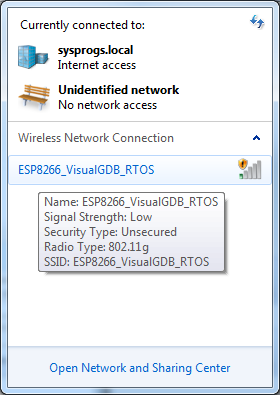
- Press F5 to start debugging the firmware. VisualGDB will program it into the SPI FLASH and start it automatically. Connect your computer or a mobile device to the ESP8266 WiFi network:
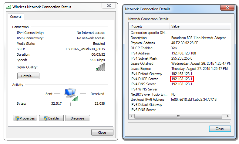
- Use the network connection status (or the ipconfig utility) to verify the IP address of the ESP8266:
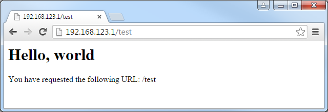
- Open the browser and enter the address there. You will see a simple “Hello, world” message followed by the URL you entered:
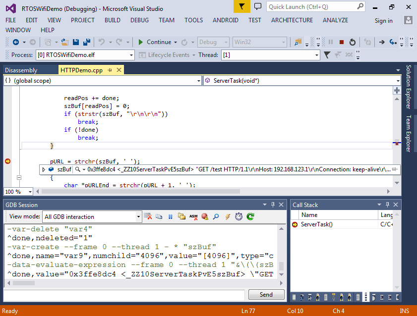
- Now we will look in the code that handles the HTTP requests. Set a breakpoint on the first call to strchr() in ServerTask() and hit the refresh button in the browser. Once the breakpoint is hit, you can see the HTTP request sent by the browser:
- The ServerTask() function uses the API provided by lwIP and does not look different from a function written for a Windows- or Linux-based environment:
- First it calls socket() to create a socket
- Then it calls bind() and listen() to begin listening on the port 80
- It calls accept() to accept incoming connections
- For each incoming connection it calls read() until the HTTP header is received and then calls write() to send the reply
- Finally it calls close() to close the client socket
Unlike the IoT SDK and the espconn API where the event handler must save its state to global variables and exit, the RTOS SDK is much easier to use and allows quickly porting network-related code from the desktop environment.
- We will now add a basic HTML form that will allow controlling the LED and the on-board relay:
<form>
    LED period: <input name="period"/>msec<input type="Submit" value="Set"/>
</form>
<form>
    Relay state:<br/>
    New State:
    <input type="Submit" name="relay" Value="A"/>
    <input type="Submit" name="relay" Value="B"/>
</form>
- Modify the global header/footer variable as follows and add the ‘format’ variable:
static const char szHeader[] = "HTTP/1.0 200 OK\r\nContent-type: text/html\r\n\r\n<html><body><h1>LED & Relay Demo</h1>"; static const char szFormat[] = "<form>LED period: <input name=\"period\" value=\"%d\"/>msec<input type=\"Submit\" value=\"Set\"/></form><form>Relay state: %s<br/>New state:<input type=\"Submit\" name=\"relay\" Value=\"A\"/><input type=\"Submit\" name=\"relay\" Value=\"B\"/></form>"; static const char szFooter[] = "</body></html>"; static int s_LEDPeriod = 300;
- Create another thread that will be blinking the LED and start it from user_init():
extern "C"
{
#include <gpio.h>
}

static void RAMFUNC LEDBlinkTask(void *pvParameters)
{
    PIN_FUNC_SELECT(PERIPHS_IO_MUX_U0TXD_U, FUNC_GPIO1);
    for (int tick = 0;; tick++)
    {
        vTaskDelay(s_LEDPeriod / portTICK_RATE_MS);
        gpio_output_conf(0, BIT1, BIT1, 0);
        vTaskDelay(s_LEDPeriod / portTICK_RATE_MS);
        gpio_output_conf(BIT1, 0, BIT1, 0);
    }
}

void RAMFUNC user_init(void)
{
    //...
    xTaskCreate(LEDBlinkTask, (signed char *)"Blink", 256, NULL, 2, NULL);
}
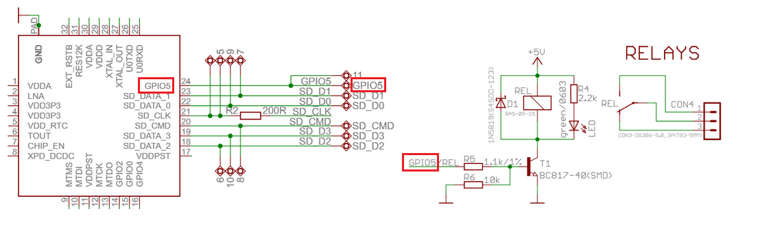
- In this tutorial we are using the ESP8266 module from Olimex that has a relay connected to GPIO5. If you are using a different board, use the schematics to find the GPIO port connected to the relay or just skip the relay-related code:
- Now we can modify the code responsible for parsing the request and sending the reply to parse the form fields and control the period and the relay:
        if (pURL)
        {
            char *pURLEnd = strchr(pURL + 1, ' ');
            if (pURLEnd)
            {
                pURL++;
                pURLEnd[0] = 0;
                const char *pRelay = strstr(pURL, "relay=");
                if (pRelay)
                {
                    if (pRelay[6] == 'A')
                        gpio_output_conf(BIT5, 0, BIT5, 0);
                    else
                        gpio_output_conf(0, BIT5, BIT5, 0);
                }
                const char *pPeriod = strstr(pURL, "period=");
                if (pPeriod)
                {
                    s_LEDPeriod = atoi(pPeriod + 7);
                }

                write(client_sock, szHeader, sizeof(szHeader) - 1);
                sprintf(szBuf, szFormat, s_LEDPeriod, (GPIO_REG_READ(GPIO_OUT_ADDRESS) & BIT5) ? "A" : "B");
                write(client_sock, szBuf, strlen(szBuf));
                write(client_sock, szFooter, sizeof(szFooter) - 1);
            }
        }
Also enable the GPIO5 in user_init():
PIN_FUNC_SELECT(PERIPHS_IO_MUX_GPIO5_U, FUNC_GPIO5);
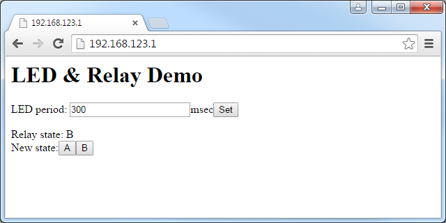
- Now you can build the new program and start it by pressing F5. Reconnect to the WiFi network and refresh the page in the browser:
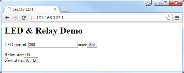
- Try changing the LED period and pressing “set” to update it, then press the “A” and “B” buttons and check that the relay is clicking. The relay has 2 states: in state A it connects the COM terminal with the NO terminal and instate B it connects COM with NC. You can use it to switch on and off various devices such as a 5V fan:

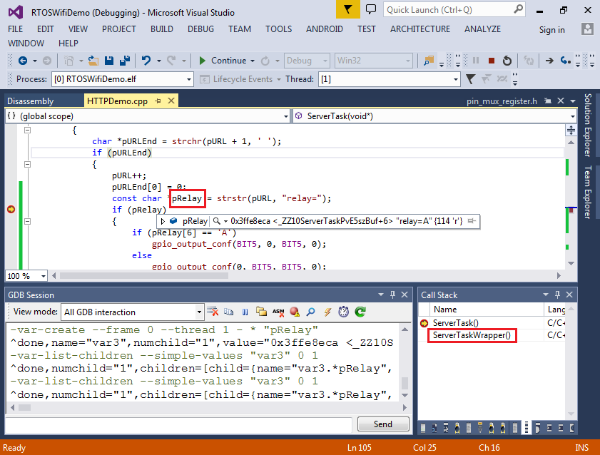
- You can set a breakpoint in the ServerTask() function, however you won’t be able to evaluate local variables as gdb won’t be able to find the function calling ServerTask(). To work around this, create the task using a wrapper function:
void RAMFUNC ServerTaskWrapper(void *pvParameters)
{
    ServerTask(pvParameters);
}
- As long as gdb can find the function’s caller, it will show the variables correctly: