Editing Hardware Register Definitions
Most of the device families supported by VisualGDB include definitions for the peripheral registers that allow viewing and modifying those registers conveniently via the Hardware Registers window: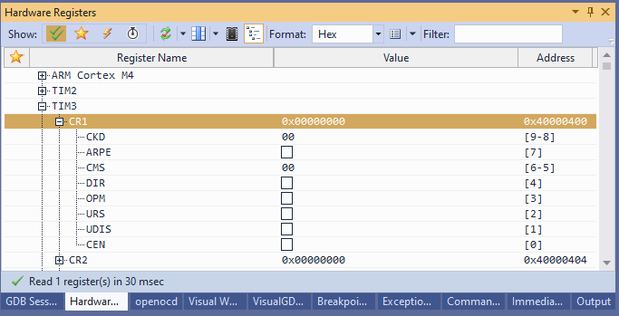 For legacy projects that are created by manually specifying the compiler settings, the hardware registers won’t be automatically shown. To fix this, open the VisualGDB Project Properties window and set the peripheral register definition file:
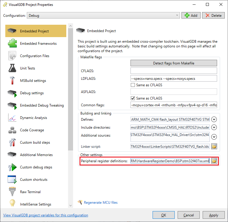 You can also use the link at the bottom of the Hardware Registers window to import the definition file into VisualGDB:
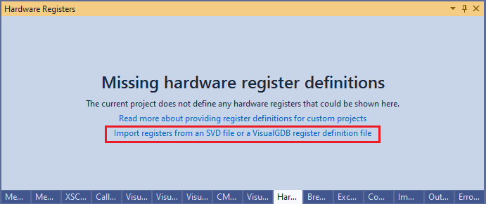 If you are using Quick Debug without a BSP, you can specify the path to a hardware register definition file as shown below:
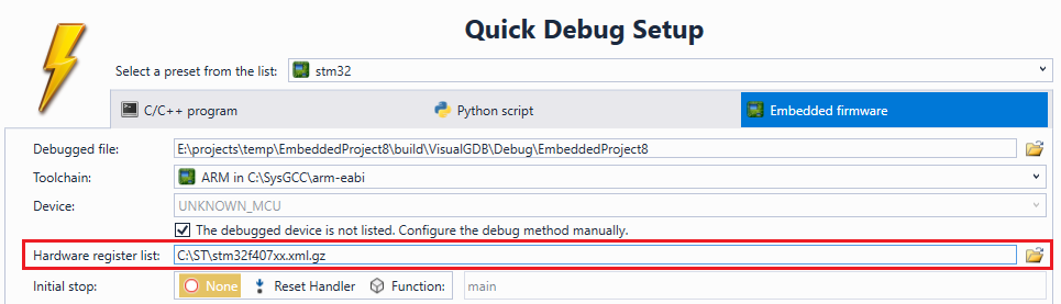
The register definition file is an XML file with the following structure:
<?xml version="1.0"?> <MCUDefinition xmlns:xsi="http://www.w3.org/2001/XMLSchema-instance" xmlns:xsd="http://www.w3.org/2001/XMLSchema"> <MCUName>DeviceName</MCUName> <RegisterSets> <HardwareRegisterSet> <ExpressionPrefix>TIM2-></ExpressionPrefix> <UserFriendlyName>TIM2</UserFriendlyName> <Registers> <HardwareRegister> <!-- ... --> </HardwareRegister> </Registers> </HardwareRegisterSet> </RegisterSets> </MCUDefinition> |
Each register set corresponds to a group of registers corresponding to the same peripheral (e.g. timer or USB). The UserFriendlyName element contains the name of the group as shown in the Hardware Registers window. The ExpressionPrefix element allows matching C/C++ Watch expressions (e.g. TIM2->CR1 to specific hardware registers defined in a peripheral register definition file).
Each HardwareRegister element corresponds to one register inside a register set. It has the following structure:
<HardwareRegister> <Name>CR1</Name> <SizeInBits>32</SizeInBits> <Address>0x40000000</Address> <ReadOnly>false</ReadOnly> <SubRegisters> <HardwareSubRegister> <Name>CEN</Name> <FirstBit>0</FirstBit> <SizeInBits>1</SizeInBits> </HardwareSubRegister> <HardwareSubRegister> <Name>UDIS</Name> <FirstBit>1</FirstBit> <SizeInBits>1</SizeInBits> </HardwareSubRegister> <HardwareSubRegister> <Name>CMS</Name> <FirstBit>5</FirstBit> <SizeInBits>2</SizeInBits> <KnownValues> <KnownSubRegisterValue> <Name>EDGE</Name> </KnownSubRegisterValue> <KnownSubRegisterValue> <Name>CENTER1</Name> </KnownSubRegisterValue> <KnownSubRegisterValue> <Name>CENTER2</Name> </KnownSubRegisterValue> <KnownSubRegisterValue> <Name>CENTER3</Name> </KnownSubRegisterValue> </KnownValues> </HardwareSubRegister> </SubRegisters> </HardwareRegister> |
Each HardwareSubRegister element corresponds to a meaningful group of bits inside the hardware register: VisualGDB will use the following rules when showing subregisters:
- Subregisters with size of 1 will be displayed as checkboxes
- Subregisters with size of k having exactly 2k KnownSubRegisterValue elements specified will be shown as combo boxes.
- All other subregisters will be shown as editable text fields containing raw values
The SubRegisters and KnownValues elements are optional; a simple register definition file may skip them.
Generated register definition files for real-world devices can be quite large. To save space VisualGDB allows storing them in a compressed format. Simply compress it with gzip and append .gz to the extension (e.g. device.xml.gz) and VisualGDB will automatically recognize and decompress it on-the-fly.
SVD Files
Many device vendors provide descriptions for the peripheral registers of their devices in the SVD format. You can normally locate these definitions by searching for *.svd files (or *.xml files in the svd subdirectory) in the SDKs. VisualGDB supports automatically importing the SVD files: once you select a .svd file instead of an file in the VisualGDB’s XML format, it will be automatically converted and imported.
Examples
To see examples of working register definition files, go to the %LOCALAPPDATA%\VisualGDB\EmbeddedBSPs directory and search for .xml.gz files. Unpack one of those files and open it in a text editor to get a real-world example of a device definition file.