Using the RGB LED on the FRDM-KL25Z board
This tutorial shows how to use the RGB LED available on the FRDM-KL25Z board. We will demonstrate the use of interrupts, hardware PWM and show how to setup basic clocks. We will create a project that will gradually shift the LED from red into green and back.
Before you begin, follow this tutorial to create a basic FRDM-KL25Z project. Once you can build and debug the basic project, follow the steps below to create the more advanced version.
- First of all we will use the built-in hardware timers to generate a periodic interrupt. In order to use them you will first need to provide them with a clock signal. Freescale Kinetis devices support various clock sources, one of them being the internal 4 MHz clock. Our first step will be to enable that clock and select it as the MCGIRCLK clock. Add the following lines to the beginning of your main() function:
MCG_BASE_PTR->C1 = MCG_C1_IREFS_MASK | MCG_C1_IRCLKEN_MASK;
MCG_BASE_PTR->C2 = MCG_C2_IRCS_MASK; //Select fast internal clock
SIM_BASE_PTR->SCGC6 |= SIM_SCGC6_TPM2_MASK; //Enable TPM2 clock
SIM_BASE_PTR->SOPT2 |= SIM_SOPT2_TPMSRC(3);
- Now we will enable the TPM2 timer, and configure it to reset itself 2 times per second. To achieve that we will divide the fast 4 MHz clock by 128 by setting the prescaler bits to 7 and further divide it by 16384 by setting the modulus register to 16383:
TPM2_BASE_PTR->SC = TPM_SC_CMOD(1) | TPM_SC_PS(7);
TPM2_BASE_PTR->MOD = 16383;
- Now we will add the interrupt handler that will toggle the PTB18 pin each time the timer generates an interrupt:
extern "C" void TPM2_Handler()
{
    PTB_BASE_PTR->PTOR = 1 << 18;
    TPM2_BASE_PTR->SC |= TPM_SC_TOF_MASK;
}
Note that if your file has the .c extension (not .cpp), you don’t need the ‘extern “C”‘ statement.
- Finally we need to configure the timer to raise an interrupt on overflow and enable the timer interrupt in the interrupt controller:
TPM2_BASE_PTR->SC |= TPM_SC_TOIE_MASK;
NVIC_BASE_PTR->ISER = 1 << 19;
- Don’t forget to remove the code writing to PSOR and PCOR registers from main(). Replace the previous for() loop with the following code:
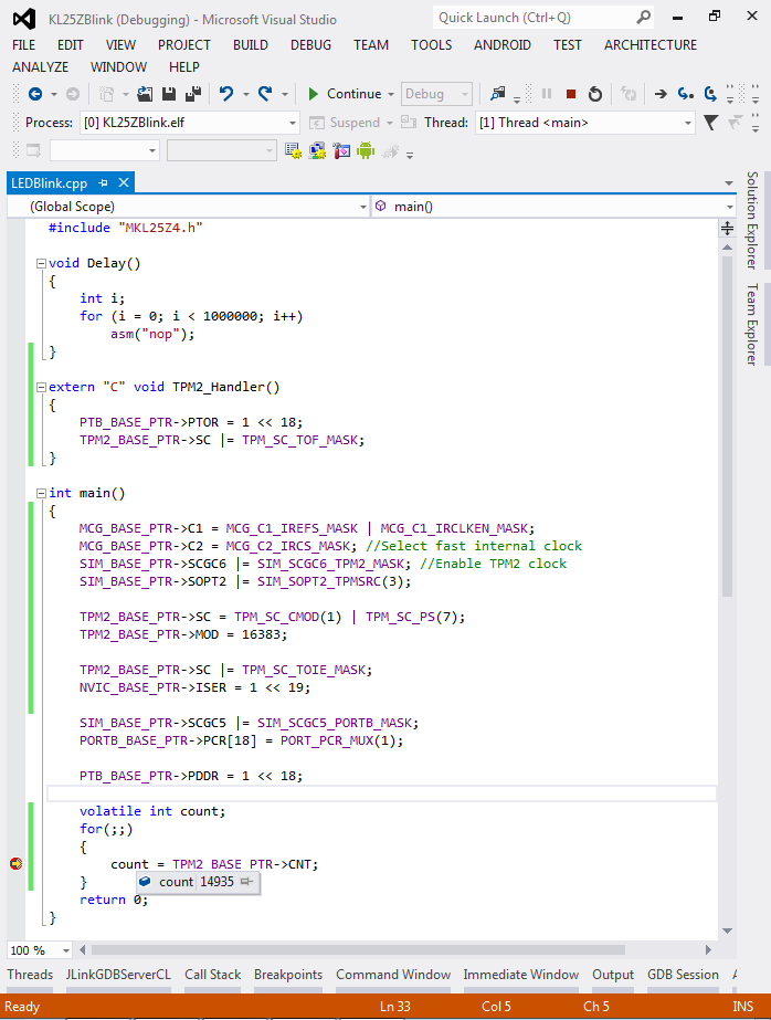
volatile int count;
for(;;)
{
    count = TPM2_BASE_PTR->CNT;
}
- If you build and run your project, you will see the red LED slowly blinking. If you put a breakpoint on the line inside the loop and inspect the value of the “count” variable, you will see how it is getting values between 0 and 16383:
- Instead of using an interrupt handler to manually change the value of the PTB18 pin you can configure the timer in the PWM mode to do it automatically. The PTB18 pin is multiplexed with channel 0 of the TPM2 module. You can switch the pin to be the TPM output instead of a normal GPIO pin by writing the PCR register (do it after PORTB clock is enabled by writing to the SGC5 register):
PORTB_BASE_PTR->PCR[18] = PORT_PCR_MUX(3);
- Now remove the code responsible for enabling the interrupts and configure the channel 0 of TPM2 to run in the PWM mode and generate short impulses (1/8 of the timer period):
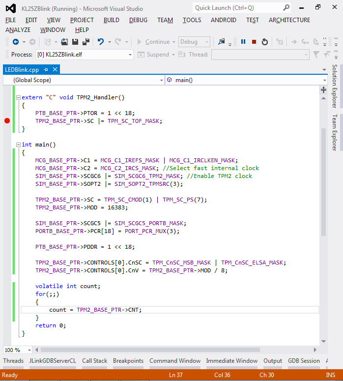
TPM2_BASE_PTR->CONTROLS[0].CnSC = TPM_CnSC_MSB_MASK | TPM_CnSC_ELSA_MASK;
TPM2_BASE_PTR->CONTROLS[0].CnV = TPM2_BASE_PTR->MOD / 8;
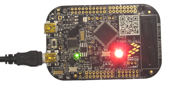
- Build and run the program. You will observe the red LED blinking in short impulses although TPM2_Handler() is never called:
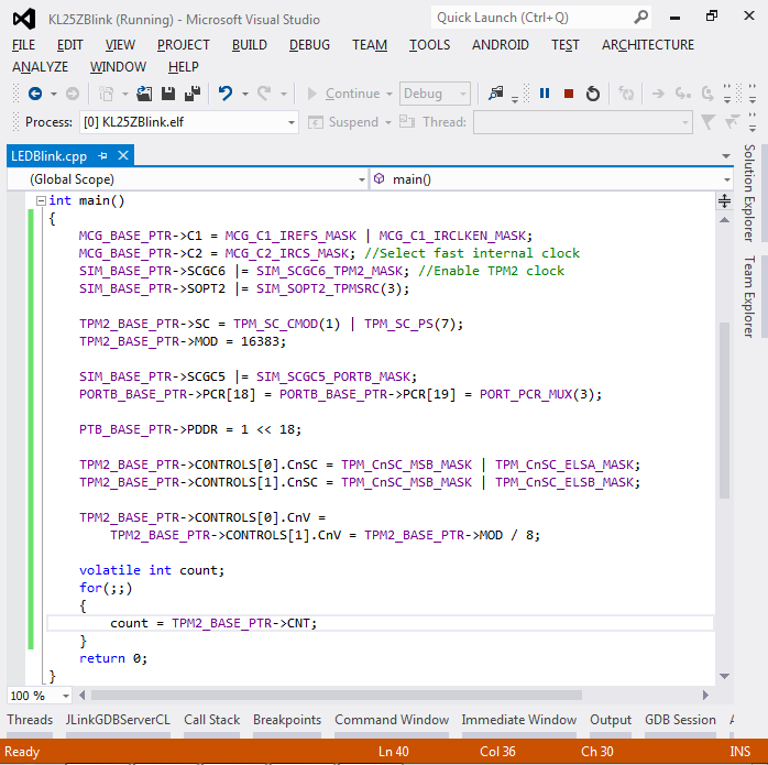
- As the green LED is connected to port PTB19 and PWM channel 1, we can configure the PWM output for it the same way as we did for the red LED. If we specify the TPM_CnSC_ELSB_MASK instead of TPM_CnSC_ELSA_MASK for channel 1, its output will be inverted and the green LED will be on only when the red LED is off and vice versa:
- Now if we increase the frequency to over 100 Hz and slowly change the red/green portion between 0 and 100% we’ll see the LED slowly going from red to green via yellow and back. Here’s the final source code:
#include "MKL25Z4.h"
#include <math.h>

void Delay(int cycles)
{
    while (cycles--)
    asm("nop");
}

int main()
{
    MCG_BASE_PTR->C1 = MCG_C1_IREFS_MASK | MCG_C1_IRCLKEN_MASK;
    MCG_BASE_PTR->C2 = MCG_C2_IRCS_MASK;
    SIM_BASE_PTR->SCGC6 |= SIM_SCGC6_TPM2_MASK;
    SIM_BASE_PTR->SOPT2 |= SIM_SOPT2_TPMSRC(3);

    TPM2_BASE_PTR->SC = TPM_SC_CMOD(1) | TPM_SC_PS(0);
    TPM2_BASE_PTR->MOD = 16383;

    SIM_BASE_PTR->SCGC5 |= SIM_SCGC5_PORTB_MASK;
    PORTB_BASE_PTR->PCR[18] = PORTB_BASE_PTR->PCR[19] = PORT_PCR_MUX(3);

    PTB_BASE_PTR->PDDR = 1 << 18;

    TPM2_BASE_PTR->CONTROLS[0].CnSC = TPM_CnSC_MSB_MASK | TPM_CnSC_ELSA_MASK;
    TPM2_BASE_PTR->CONTROLS[1].CnSC = TPM_CnSC_MSB_MASK | TPM_CnSC_ELSB_MASK;

    for(double phase = 0;;phase += 0.005)
    {
        double portion = 0.5 + sin(phase) / 2;
        TPM2_BASE_PTR->CONTROLS[0].CnV = TPM2_BASE_PTR->CONTROLS[1].CnV = TPM2_BASE_PTR->MOD * portion;
        Delay(1000);
    }
    return 0;
}
The LED will be gradually switching from red to green and back:
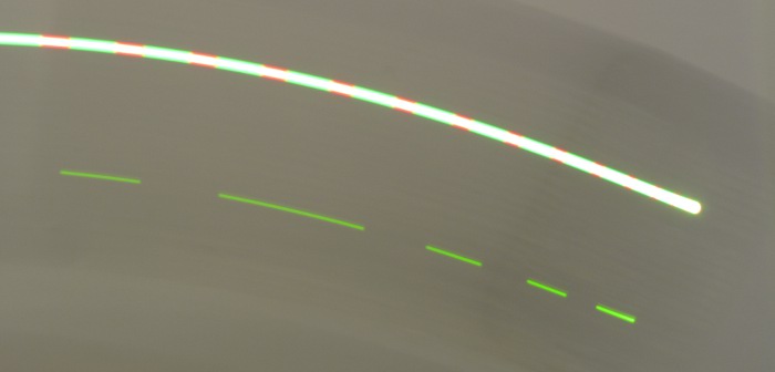
- If you now move the board around very fast, you will be actually able to see a striped line. The picture below taken with the exposure time of 1/4 seconds clearly shows the effect: