Using STM32 Hardware Floating Point Support
This tutorial shows how to use the hardware floating-point module present on STM32F4 devices. We will demonstrate the use of floating point by producing a “breathing LED effect” – gradually turning the LED on and off. The LED itself cannot be ‘partially on’, however if we quickly turn it on and off (>100Hz) having it on X% of the time, it will look like the LED is at the X% of its maximum brightness:
The proportion of the time when the LED is on is called duty cycle. To achieve the “breathing effect” we will adjust the duty cycle gradually according to the sine waveform:
The PWM pulse width will hence be calculated as T·(1 +
sin(arg)) / 2, where T is the PWM period and arg is a floating-point counter that we keep increasing in small increments.
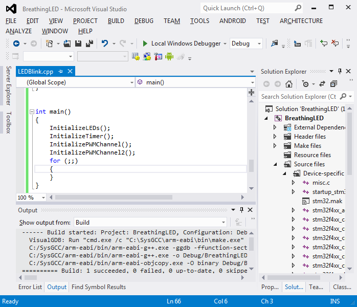
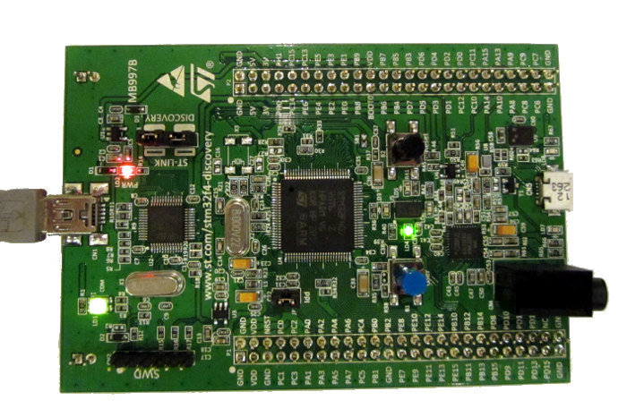
- Follow our PWM tutorial to create a basic PWM blinking LED program. Use the default ‘software floating point mode’ for the beginning. Build the project and run it to ensure that it works:
- Now we will modify the PWM sample to produce a basic ‘breathing effect’. First of all, change the prescaler in InitializeTimer() from 40000 to 1. This will increase the timer frequency to a point where the blinking is not noticeable anymore:
timerInitStructure.TIM_Prescaler = 1;
- Then include the <math.h> file and replace the contents of main() with the following:
const int period = 1000;

InitializeLEDs();
InitializeTimer(period);
InitializePWMChannel();
for (float arg = 0;;arg += 0.0001F)
{
    uint32_t pulseWidth = (period / 2) * (1 + sinf(arg));
    TIM_SetCompare1(TIM4, pulseWidth);
}
- Build and start debugging your program. Notice the smooth LED ‘breathing’. Set a breakpoint on the line calling the sinf() function and once it is hit go to disassembly:
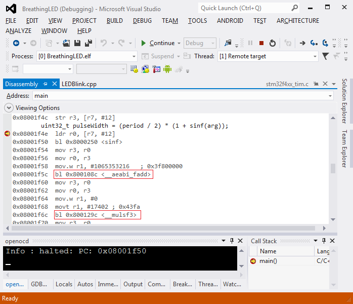 Note how addition and multiplication have been implemented by calling the library functions (with arguments being passed via general-purpose registers).
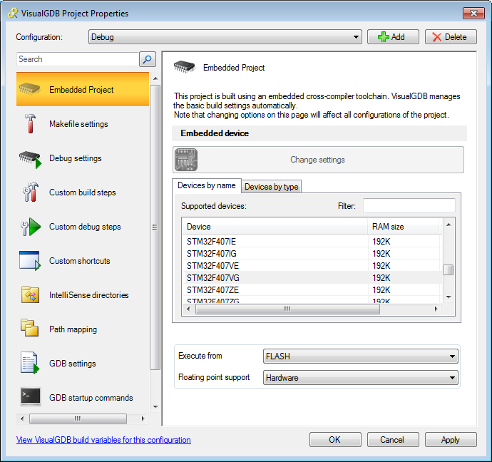
 - Now we will change the floating-point mode to hardware. Go to VisualGDB Project Properties, press “Change Settings” and select “Hardware” in “floating point support”:
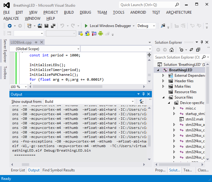
- Press OK and rebuild your project. Note that -mfloat-abi=hard has been added to GCC flags:
- Press F5 to start debugging. Note how the LED ‘breathing’ has become significantly faster as each iteration of the loop now takes fewer time to complete:
- Set a breakpoint on the line calling sinf(). Once it hits, open the Disassembly view:
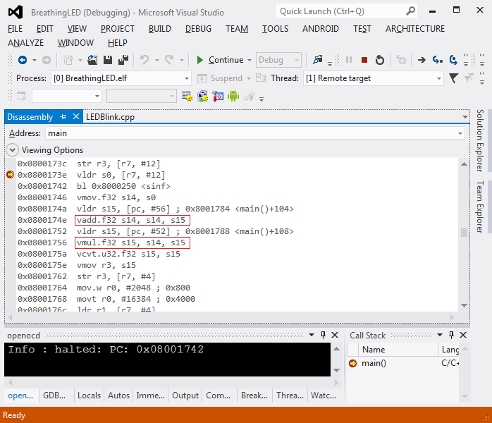 Note how addition and multiplication now take one instruction each (vadd/vmul). Sine is still computed by calling a library function.
 - STM32F4 floating-point unit only supports 32-bit floating point numbers (float type, but not the double type). If you are using an older GCC version, it will still try to generate hardware floating-point instructions for operations with double that will cause a run-time exception. We will demonstrate it now. Change ‘float‘ to ‘double‘ in the loop declaration, build and run your program. Once the program is running (and the LED looks frozen) select Debug->Break All:
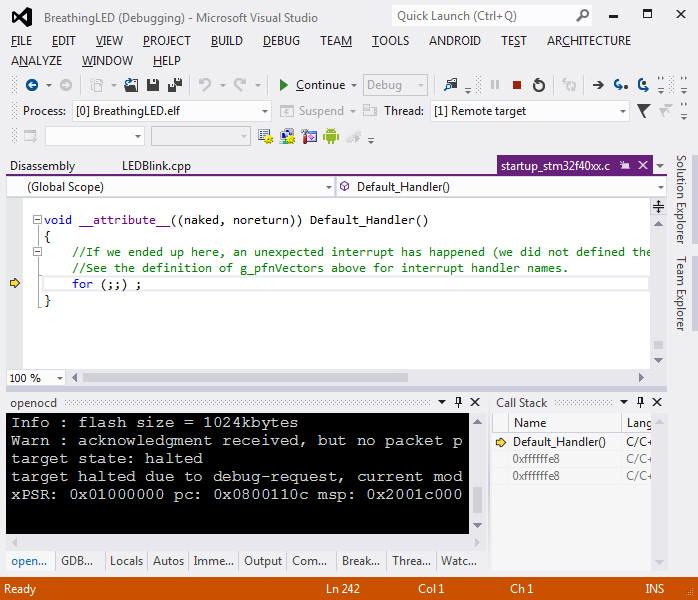
- You will see that the program is stopped at the exception handler, and the call stack does not provide meaningful information about the cause of the exception. This happens because GDB does not know how to unwind ARM exception frames, so we need to do it manually. Open the Memory view and type “$sp” in the Address field:
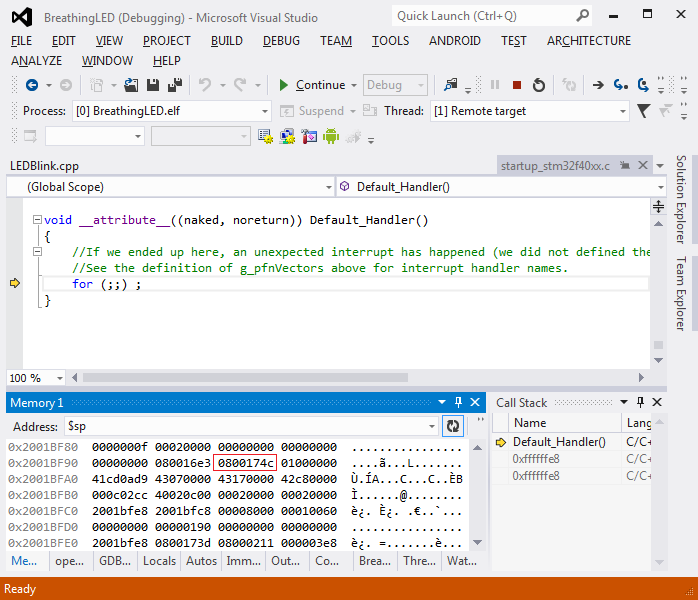
- According to the ARM documentation, the value of the PC register when the exception happened is stored under [pc + 0x18]. Copy that value into the Disassembly window (prefix it with 0x):
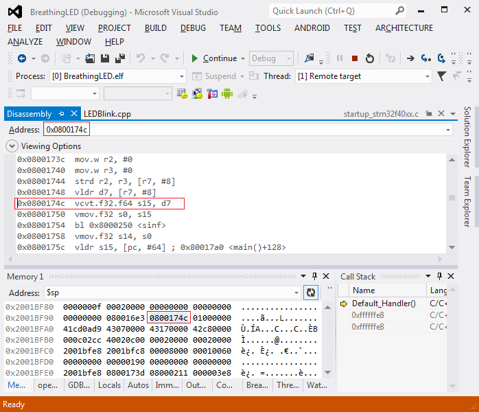 In this example the exception was caused by the vcvt.f32.f64 instruction that is not supported on STM32F4 devices due to lack of 64-bit floating point support. Use a more recent toolchain to support double properly. Our toolchains starting from gcc 4.9.1 include a fix that resolves the double handling for cortex devices in hardware FP mode.


