Using MQTT to remotely control an ESP8266 board
This tutorial shows how to use the MQTT protocol to remotely control the LED on the ESP8266 board and to monitor the state of the on-board button.
MQTT is a protocol that allows exchanging short messages between different small devices. It is optimized to use as little traffic as possible and to run on small devices like ESP8266.
MQTT communication involves a central MQTT broker (e.g. Mosquitto running on Raspberry Pi) and one or more MQTT clients. A client can subscribe to one or more topics and then once any other client posts a message to that topic, the subscribed clients will receive the message. The routing of messages is done by the MQTT broker, so the clients don’t need to handle that. In our example the ESP8266 board will subscribe to a topic called led and will turn the on-board LED on when someone sends ‘1’ to that topic and off when ‘0’ is sent instead. On the PC side we will run a basic program that will send ones and zeroes to the led topic to control the LED: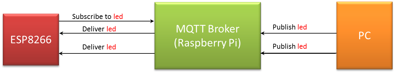 The advantage of the MQTT protocol over just sending ones and zeroes via TCP or UDP is automatic configuration. The PC does not need to know how many ESP8266 boards are listening to the led topic. All it needs to do is send a message to the MQTT broker and every node that subscribed for this topic will receive. Likewise, the ESP8266 does not need to know which PC is currently controlling the LED. As long as it is subscribed to the led topic, the MQTT broker will route the messages automatically.
Before you begin, install VisualGDB 5.2 or later and update your ESP8266 toolchain to the latest version. Then install the mosquitto broker on your Raspberry Pi (or any other Linux machine) and ensure it is running: Now we can begin with the main part of the tutorial.
- Start Visual Studio and open the VisualGDB Embedded Project Wizard:
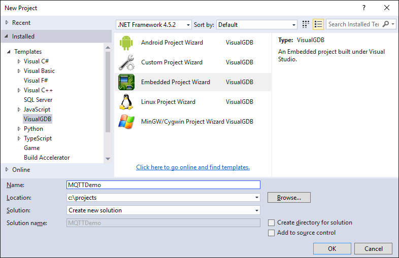
- Select “Create a new project -> MSBuild”:

- Select the ESP8266 toolchain and proceed with the regular ESP8266 device:
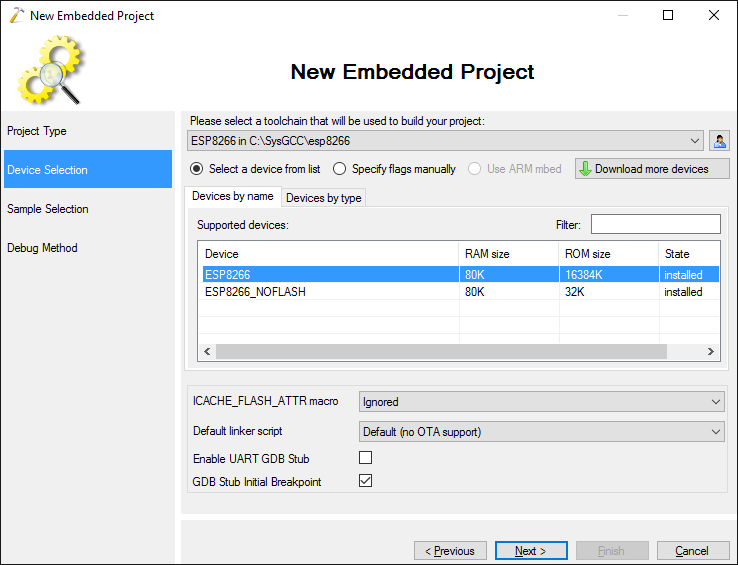
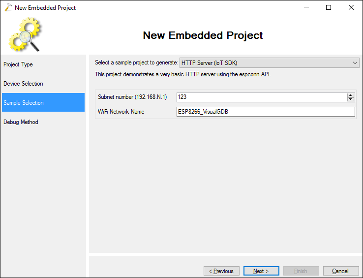
- The MQTT is currently supported by the IoT SDK (a.k.a. NONOS SDK) only, so select the HTTP Server (IoT SDK) sample:
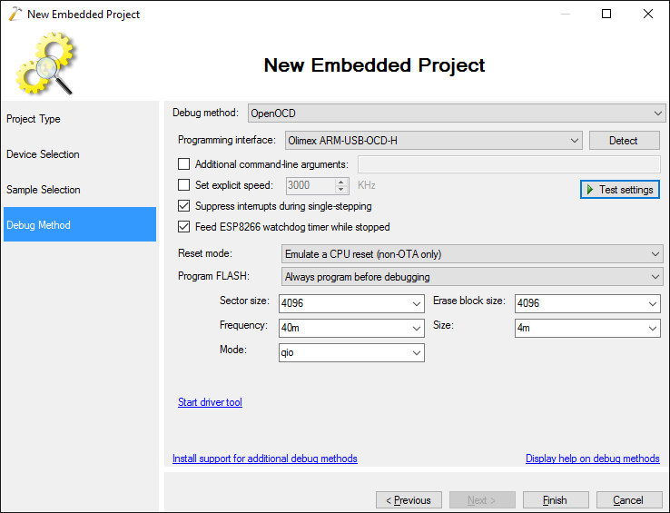
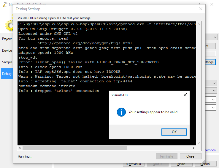
- On the Debug Method page select OpenOCD, connect your JTAG programmer to ESP8266, pick your programming interface and click “Test settings” to automatically check the connection:
- Once the JTAG connection is tested, press “Finish” to generate the project:
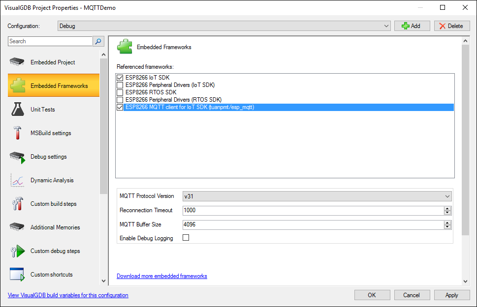
- Open VisualGDB Project Properties for the newly generated project and add a reference to the MQTT client. This will automatically add a reference to an open-source esp_mqtt library:
- Replace the contents of your main source file with the following:
extern "C"
{
    #include "ets_sys.h"
    #include "osapi.h"
    #include "mqtt.h"
    #include "wifi.h"
    #include "debug.h"
    #include "gpio.h"
    #include "user_interface.h"
    #include "mem.h"
    #include "espmissingincludes.h"
    #include "gpio.h"
}

static MQTT_Client s_MQTTClient;

static os_timer_t s_Timer;

extern "C" void ICACHE_FLASH_ATTR user_init(void)
{
    #error TODO: enter Raspberry Pi address below
    MQTT_InitConnection(&s_MQTTClient, (uint8_t*)"<YOUR RASPBERRY PI IP ADDRESS>", 1883, 0);
    if (!MQTT_InitClient(&s_MQTTClient, (uint8_t*)"client", 0, 0, 100, 0))
    {
        os_printf("Failed to initialize properly. Check MQTT version.\r\n");
        return;
    }

    MQTT_InitLWT(&s_MQTTClient, (uint8_t*)"/lwt", (uint8_t*)"offline", 0, 0);
    MQTT_OnConnected(&s_MQTTClient, mqttConnectedCb);
    MQTT_OnDisconnected(&s_MQTTClient, mqttDisconnectedCb);
    MQTT_OnPublished(&s_MQTTClient, mqttPublishedCb);
    MQTT_OnData(&s_MQTTClient, mqttDataCb);

    #error TODO: enter WiFi network settings below
    WIFI_Connect((uint8_t*)"<YOUR WIFI NETWORK NAME>", (uint8_t*)"<YOUR WIFI NETWORK PASSWORD>", wifiConnectCb);
    os_timer_setfn(&s_Timer, TimerFunction, NULL);
    os_timer_arm(&s_Timer, 100 , 1);
}
Do not forget to substitute the IP address of your Raspberry Pi and your Wi-Fi network settings to the lines marked with #error.
- Add a function that will start the MQTT connection once the Wi-Fi connection is established:
static void wifiConnectCb(uint8_t status)
{
    if (status == STATION_GOT_IP) {
        MQTT_Connect(&s_MQTTClient);
    }
    else {
        MQTT_Disconnect(&s_MQTTClient);
    }
}
- Add mqttConnectedCb() function that will subscribe to the “led” topic and a two other callbacks for other MQTT events:
static void mqttConnectedCb(uint32_t *args)
{
    MQTT_Client* client = (MQTT_Client*)args;
    os_printf("MQTT: Connected\r\n");
    MQTT_Subscribe(client, "led", 0);
}

static void ICACHE_FLASH_ATTR mqttDisconnectedCb(uint32_t *args)
{
    MQTT_Client* client = (MQTT_Client*)args;
    os_printf("MQTT: Disconnected\r\n");
}

static void ICACHE_FLASH_ATTR mqttPublishedCb(uint32_t *args)
{
    MQTT_Client* client = (MQTT_Client*)args;
    os_printf("MQTT: Published\r\n");
}
- Now add a function that will turn the LED on and off when someone posts to the “led” topic:
static void mqttDataCb(uint32_t *args, const char* topic, uint32_t topic_len, const char *data, uint32_t data_len)
{
    static bool initialized;

    if (!initialized)
    {
        initialized = true;
        gpio_init();
        PIN_FUNC_SELECT(PERIPHS_IO_MUX_U0TXD_U, FUNC_GPIO1);
    }

    if (topic_len == 3 && !memcmp(topic, "led", topic_len))
    {
        if (data_len >= 1 && data[0])
            gpio_output_set(0, BIT1, BIT1, 0);
        else
            gpio_output_set(BIT1, 0, BIT1, 0);
    }
}
- We will also add a small function that will periodically poll the GPIO inputs of the ESP8266 and send them to the “inputs” topic so that the PC can check whether the on-board button is pressed:
void TimerFunction(void *arg)
{
    unsigned gpioState = gpio_input_get();
    MQTT_Publish(&s_MQTTClient, "inputs", (char *)&gpioState, 4, 2, 0);
}
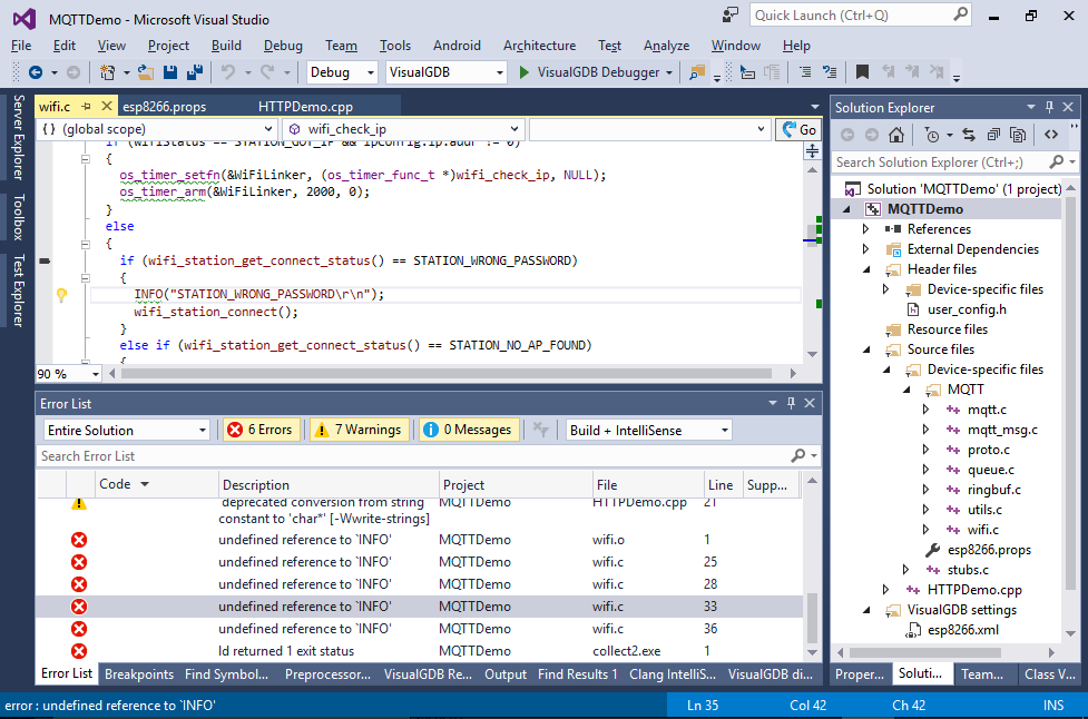
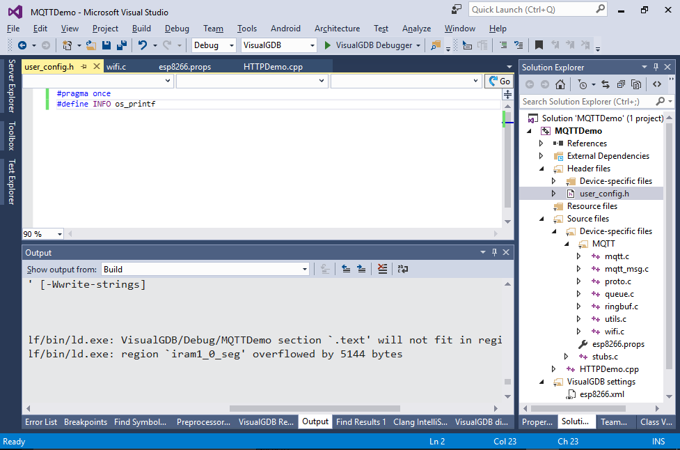
- Try building the code. You should get an error that the INFO() function is not found. This happens because the ESP8266 MQTT library expects your code to define it as a macro in user_config.h:
- Add the macro so that it calls os_printf(). Now you will get the “region iram1_0_seg overflowed” message:
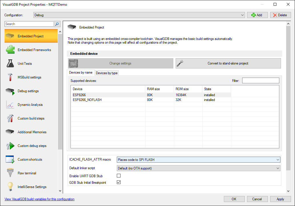
- This happens because too much code got placed into RAM. Open VisualGDB Project Properties and configure the ICACHE_FLASH_ATTR macro to actually place code into FLASH:
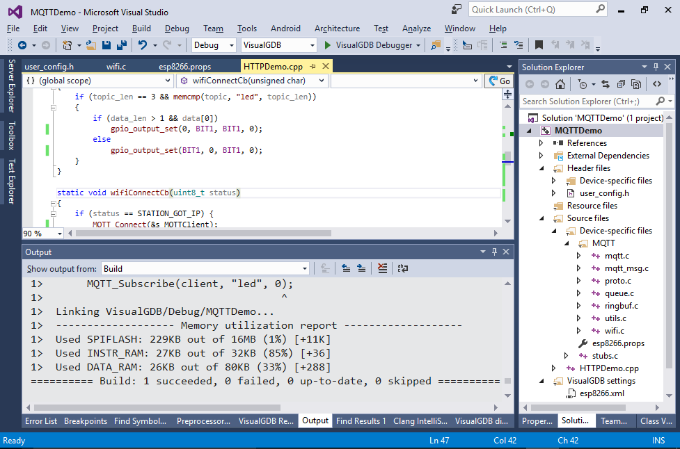
- Now the build should succeed:
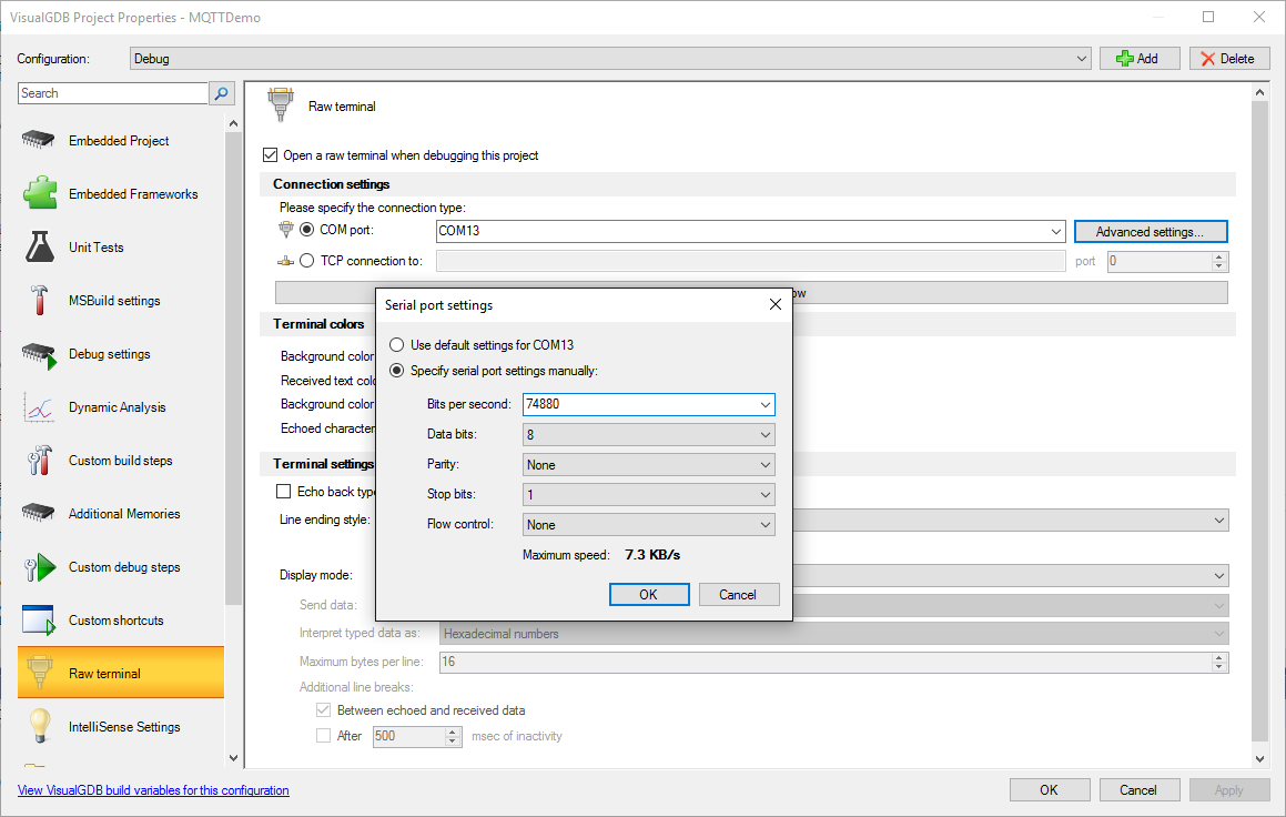
- If you are using the Custom edition of VisualGDB or higher and your ESP8266 UART port is connected to a COM-to-USB adapter, you can configure the Raw Terminal in VisualGDB Project Properties to connect to it and display the ESP8266 debug output inside Visual Studio:
- Press F5 to start debugging. VisualGDB will automatically program the SPI FLASH and start debugging:
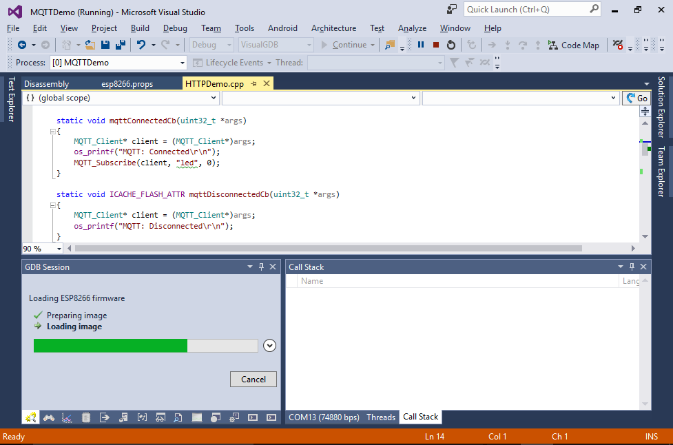
- Verify that the ESP8266 joins your Wi-Fi network and connects to the MQTT broker. The UART output should contain something similar to this:
rf cal sector: 120
rf[112] : 03
rf[113] : 00
rf[114] : 01

SDK ver: 2.0.0(656edbf) compiled @ Jul 19 2016 17:58:40
phy ver: 1055, pp ver: 10.2

WIFI_INIT
mode : sta(18:fe:34:a2:06:eb)
add if0
f r0, STATION_IDLE
STATION_IDLE
STATION_IDLE
scandone
state: 0 -> 2 (b0)
STATION_IDLE
state: 2 -> 3 (0)
state: 3 -> 5 (10)
add 0
aid 4
cnt

connected with <SSID>, channel 2
dhcp client start...
STATION_IDLE
STATION_IDLE
STATION_IDLE
STATION_IDLE
STATION_IDLE
STATION_IDLE
STATION_IDLE
ip:192.168.0.223,mask:255.255.255.0,gw:192.168.0.1
MQTT: Connected
MQTT: Published
MQTT: Published
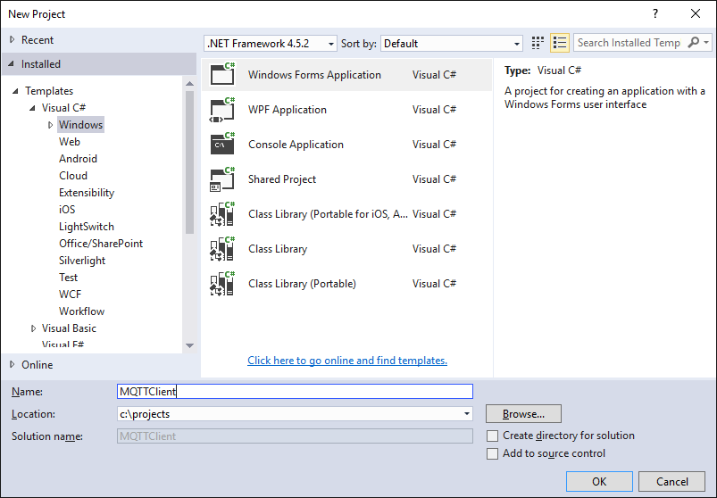
- Now we will create a very basic Windows MQTT client in C#. Open another instance of Visual Studio and create a Windows Forms application:
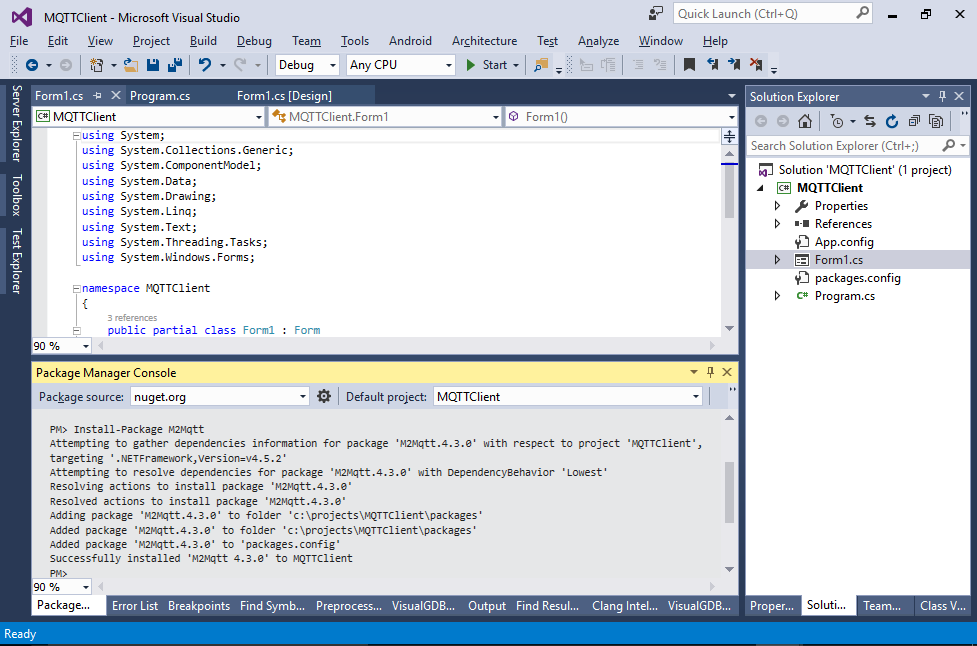
- Open View->Other Windows->Package Manager and type the following command there:
Install-Package M2MqttThis will automatically download the C# MQTT client package and reference it from your application:
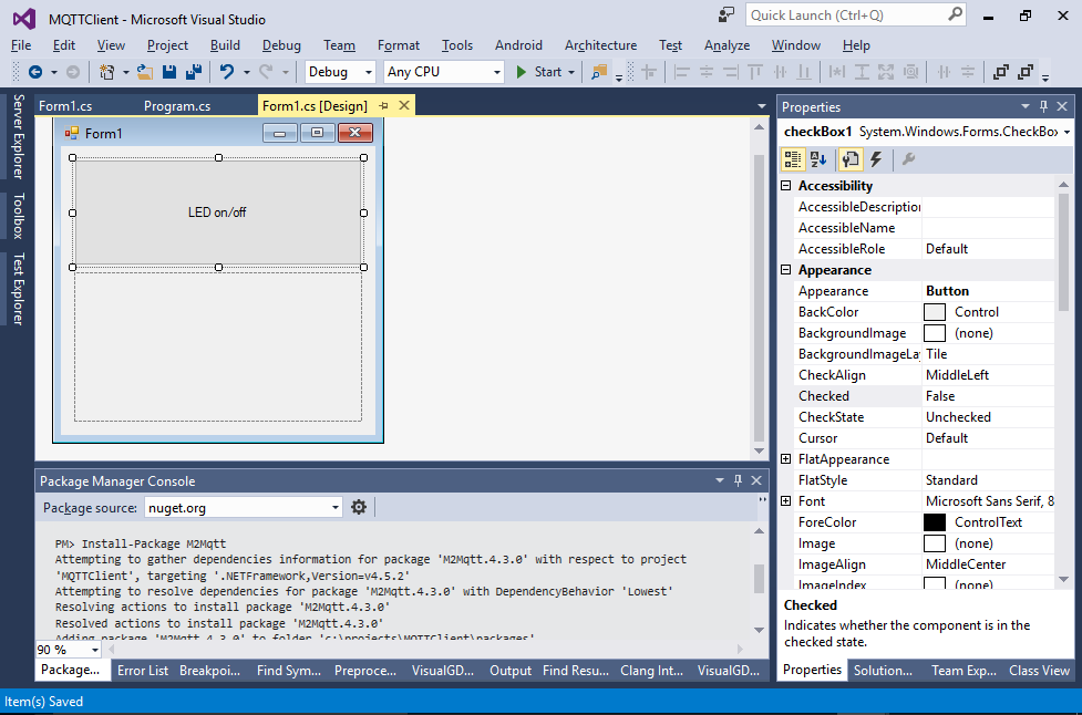
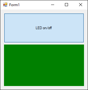
- Place a checkbox and a panel on your form. You can change the Appearance parameter of the checkbox to make it look like a button:
- Replace contents of Form1.cs with the following code:
using System;
using System.Collections.Generic;
using System.ComponentModel;
using System.Data;
using System.Drawing;
using System.Linq;
using System.Text;
using System.Threading;
using System.Threading.Tasks;
using System.Windows.Forms;
using uPLibrary.Networking.M2Mqtt;
using uPLibrary.Networking.M2Mqtt.Messages;

namespace MQTTClient
{
    public partial class Form1 : Form
    {
        private MqttClient _Client;

        public Form1()
        {
            InitializeComponent();
            _Client = new MqttClient("raspberrypi");
            _Client.Connect("C#Client");
            _Client.Subscribe(new[] { "inputs" }, new byte[] { MqttMsgBase.QOS_LEVEL_EXACTLY_ONCE });
            _Client.MqttMsgPublishReceived += _Client_MqttMsgPublishReceived;
        }

        private void _Client_MqttMsgPublishReceived(object sender, MqttMsgPublishEventArgs e)
        {
            BeginInvoke(new Action(() =>
            {
                uint inputs = BitConverter.ToUInt32(e.Message, 0);
                if ((inputs & 1) == 0)
                    panel1.BackColor = Color.Green;
                else
                    panel1.BackColor = Color.Transparent;
            }));
        }

        private void checkBox1_CheckedChanged(object sender, EventArgs e)
        {
            _Client.Publish("led", new [] { checkBox1.Checked ? (byte)1 : (byte)0 });
        }
    }
}
Do not forget to assign checkBox1_CheckedChanged() as a CheckedChanged handler for the checkbox so that the client can actually publish the messages to led when you click it.
- Start your C# program and try pressing the button on the ESP8266 board. The panel should change its color to green when the button is pressed:
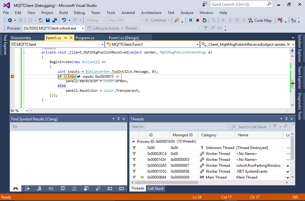
- You can see what is going on by placing a breakpoint inside the _Client_MqttMsgPublishReceived() method. The inputs variable will hold the GPIO inputs sampled by the ESP8266 board and reported via the inputs channel:
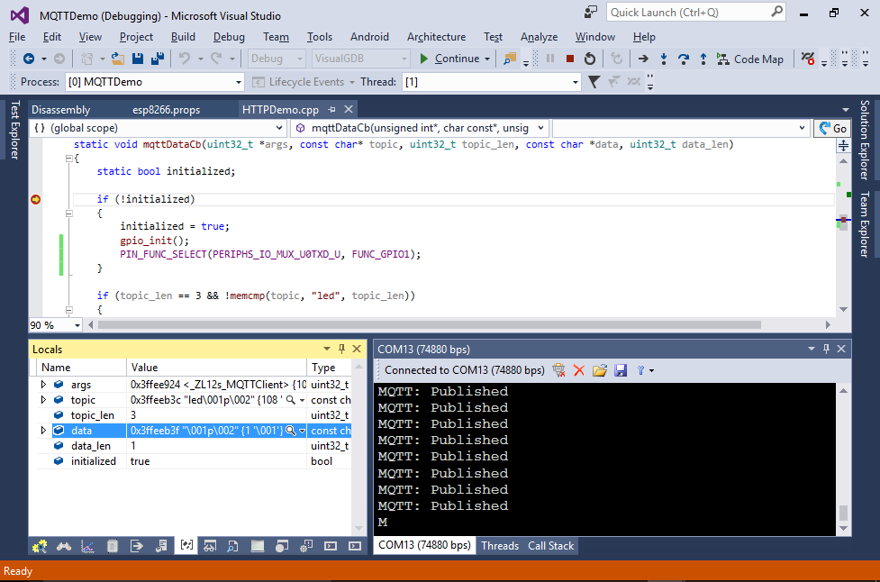
- Try clicking at the checkbox and observe the ESP8266 LED. See how it turns on and off. You can set a breakpoint in the mqttDataCb() function to see how the message gets delivered:
 Warning: the LED and the UART TX signal share the same pin. Turning the LED on or off will disrupt the debug output via UART.


The esp_mqtt library shown in this tutorial only works with the ESP8266 IoT SDK and is not compatible with the FreeRTOS SDK. If you want to use MQTT in a FreeRTOS-based application, you can try porting the official MQTT client library for embedded devices that supports FreeRTOS, but does not yet have an ESP8266-specific port.