Debugging NodeMCU Firmware over JTAG
This tutorial shows how to debug ESP8266 firmware running on your NodeMCU board using JTAG. We will show how to setup the necessary connections and configure the software to automatically program the FLASH memory and debug the firmware.
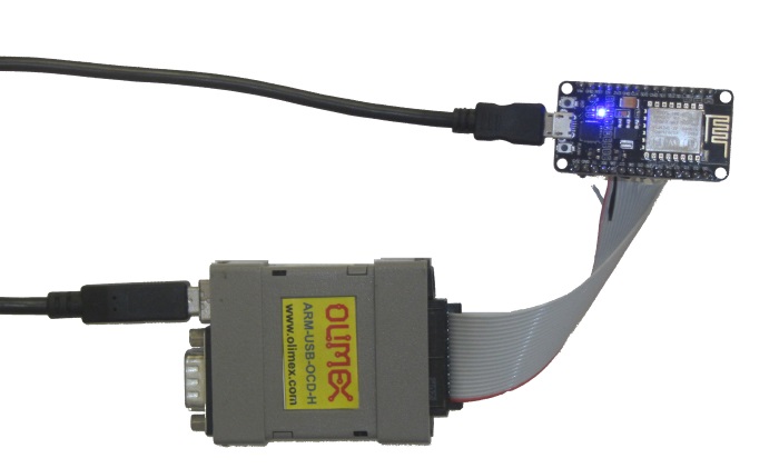
In this tutorial we will use the Olimex ARM-USB-OCD-H JTAG debugger. Other JTAG debuggers may work as well, however they may need slightly different configuration.
Before you begin, install VisualGDB 5.2 or later.
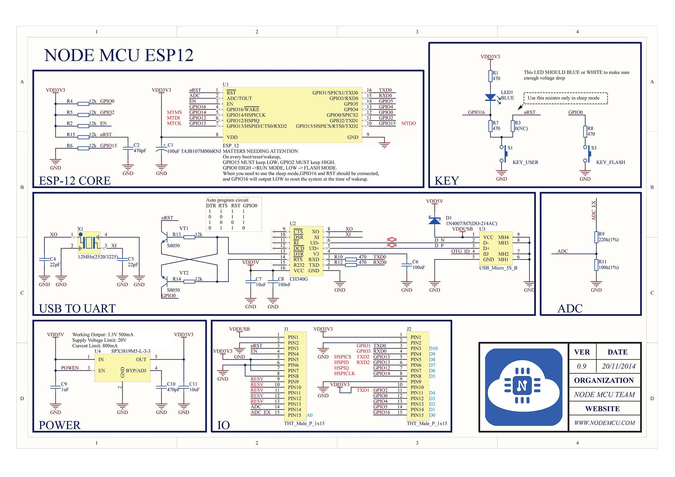
- The first step will be to connect the JTAG pins of the ESP8266 chip on the NodeMCU to your JTAG debugger. The relevant pins are VCC, GND, TDI, TDO, TMS, TCK and RESET. For NodeMCU v1, they should be connected as follows (see NodeMCU schematic and ESP-12 schematic):
ESP8266 Signal ESP8266 Pin NodeMCU Signal NodeMCU Pin JTAG20 Signal JTAG20 Pin VDDPST 17 VDD3V 1 on J2 VDD 1 VDD PAD GND 2 on J2 GND 4 MTDI 10 GPIO12 7 on J2 TDI 5 MTMS 9 GPIO14 8 on J2 TMS 7 MTCK 12 GPIO13 6 on J2 TCK 9 MTDO 13 GPIO15 5 on J2 TDO 13 EXT_RSTB 32 RST 3 on J1 nTRST or nSRST 3 (Olimex) or 15 (Segger) 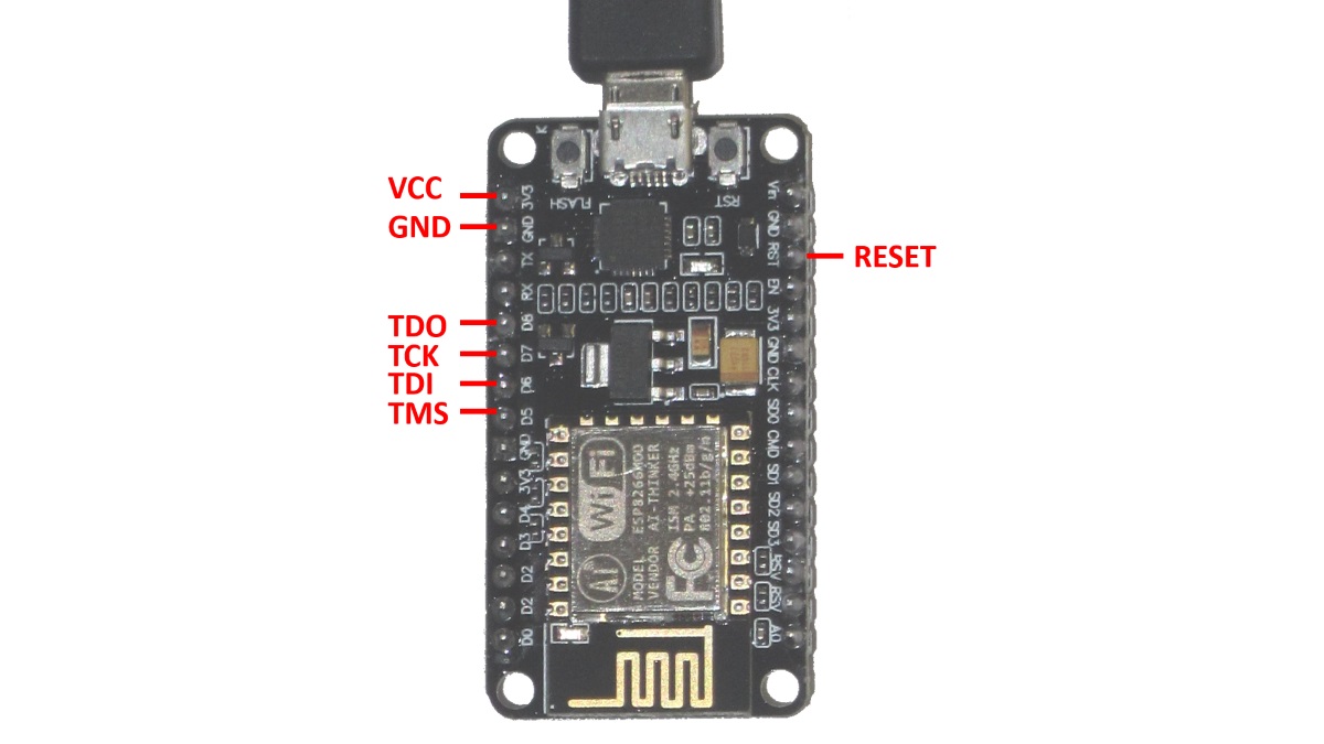
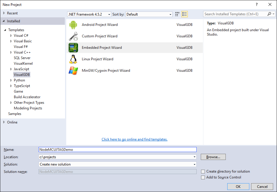
- Once you have connected all the pins, start Visual Studio and open the VisualGDB Embedded Project Wizard:
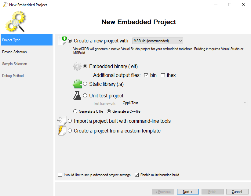
- Proceed with the default “Embedded binary” setting:
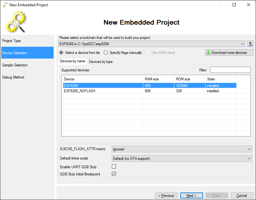
- Select the ESP8266 toolchain and the regular ESP8266 device:
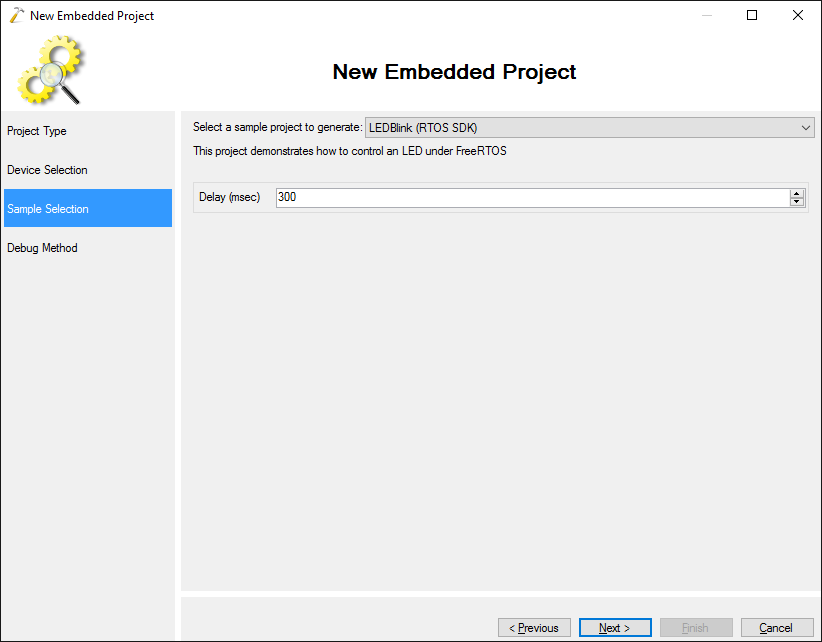
- On the Sample Selection page choose “LEDBlink (RTOS SDK)”:
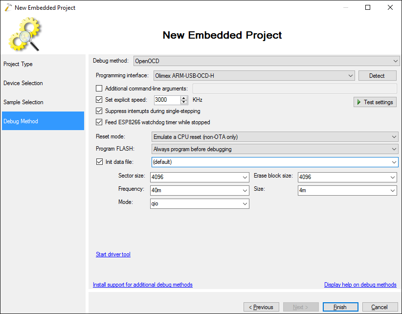
- On the Debug Setings page choose OpenOCD. Then connect your NodeMCU and the JTAG debugger via USB and click “Detect” to automatically detect the interface:
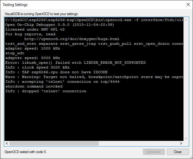
- Click “Test” to automatically test the connection between the JTAG debugger and NodeMCU:
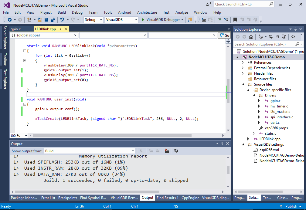
- Press “Finish” to generate your project. On NodeMCU the LED is connected to the special GPIO16 pin that is controlled differently from regular GPIO, so replace user_init() and LEDBlinkTask() with the following code:
static void RAMFUNC LEDBlinkTask(void *pvParameters)
{
    for (int tick = 0;;tick++)
    {
        vTaskDelay(300 / portTICK_RATE_MS);
        gpio16_output_set(1);
        vTaskDelay(300 / portTICK_RATE_MS);
        gpio16_output_set(0);
    }
}

void RAMFUNC user_init(void)
{
    gpio16_output_conf();

    xTaskCreate(LEDBlinkTask, (signed char *)"LEDBlinkTask", 256, NULL, 2, NULL);
}
- Press Ctrl-Shift-B to build your project:
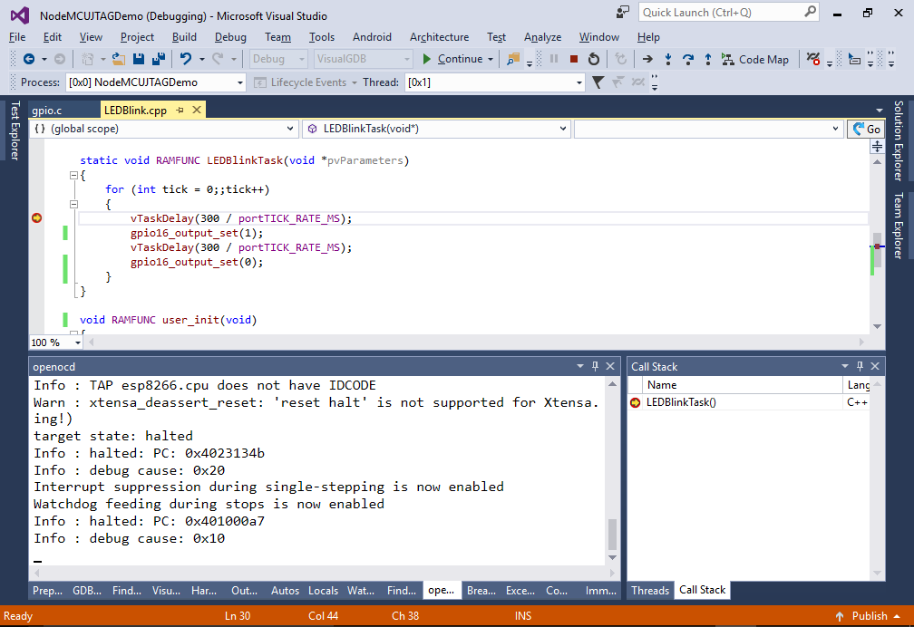
- Now press F5 to start debugging. The blue LED on NodeMCU should begin blinking:
- Set a breakpoint in the LEDBlinkTask and ensure it hits:
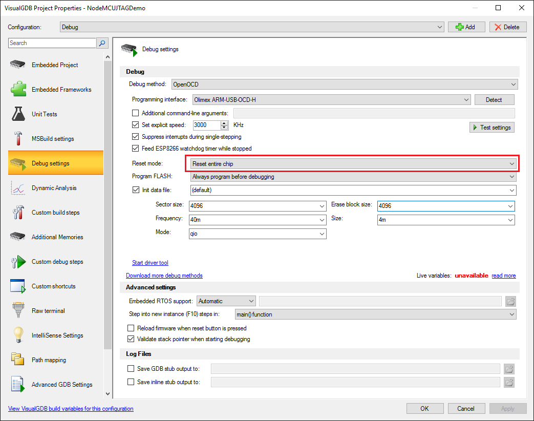
- If the LED does not start blinking after programming, try experimenting with the “Reset mode” setting in VisualGDB Project Properties: