Creating a “Blinking LED” project for Raspberry PI
This tutorial demonstrates how to attach a LED to the expansion connector on your Raspberry PI and to make it blink with a simple C++ program.
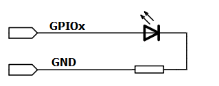
- First of all, in order to programmatically switch a LED on and off we need to connect it between a general-purpose input/output pin (GPIO) and the ground. Then we need to change the state of the pin between 1 and 0 to switch the LED on and off. The basic schematics is depicted below:
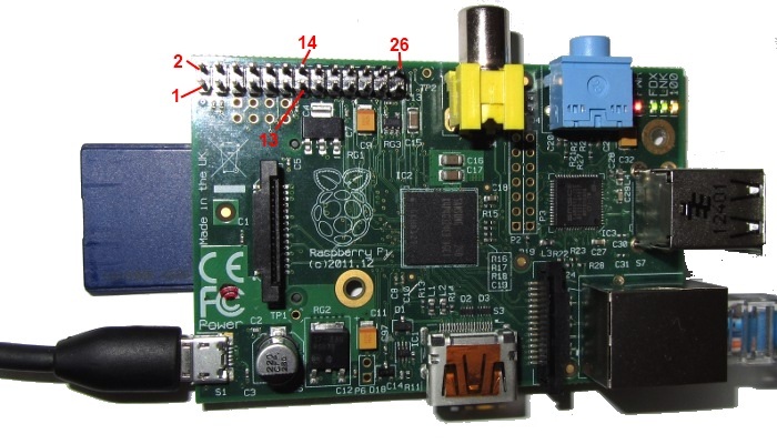
- Raspberry PI has an extension header called P1 that contains 26 pins. Not all of the pins can be controlled programmatically, so we will refer to the schematics to find out which ones can be controlled:

- According to the schematics above, pin #13 corresponds to a software-controllable GPIO27 and pin #14. Here’s how this looks on the board:
- We will now connect our external LED with a
resistor to pins 13 and 14 of the connector P1. This
requires soldering together a LED, a resistor and a pair of
connectors compatible with P1 pins: Warning! Mishandling things while or after soldering may burn your Raspberry PI and even your PC connected to it via USB! We assume no liability for any damages related to following or misfollowing this tutorial. If you still feel like experimenting, do not solder anything on a circuit that is currently powered or connected to a powered device. Be careful when connecting things, as short-circuiting certain pins will restart (and might even burn) our board and any devices attached to it. Use an expandable USB phone charger instead of your actual computer as the power source.
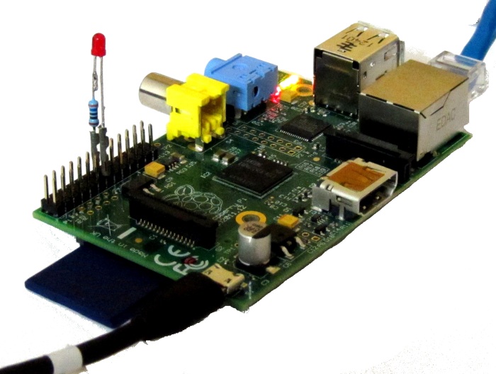
 - Turn off your Raspberry PI board and carefully connect the LED to the P1 header. Ensure that you have not short-circuited any adjacent pins. Use a multimeter to be 100% sure. When done all checks, turn it on:
- According to the schematics above, we have connected our LED to GPIO27. In order to turn the LED on programmatically, logon to the Raspberry PI over SSH and run the following commands:
sudo su
cd /sys/class/gpio
echo 27 > export
cd gpio27
echo out > direction
echo 1 > value
- Once you enter the last command you will see the LED go on:
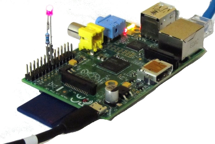
- You can switch it off again by typing the following command:
echo 0 > value
- Now we will make a simple C++ program that will make the LED blink by automating the commands we used above. Make a basic C++ project for Raspberry PI. Follow this tutorial to set it up with just a few clicks within Visual Studio.
- Ensure that you will be running your program as root:

- Add the following code to your main() function:
#include <unistd.h>
#include <string.h>
#include <stdio.h>
#include <fcntl.h>

class LinuxFile
{
private:
   int m_Handle;

public:
    LinuxFile(const char *pFile, int flags = O_RDWR)
    {
        m_Handle = open(pFile, flags);
    }

    ~LinuxFile()
    {
       if (m_Handle != -1)
            close(m_Handle);
    }

    size_t Write(const void *pBuffer, size_t size)
    {
        return write(m_Handle, pBuffer, size);
    }

    size_t Read(void *pBuffer, size_t size)
    {
        return read(m_Handle, pBuffer, size);
    }

    size_t Write(const char *pText)
    {
        return Write(pText, strlen(pText));
    }

    size_t Write(int number)
    {
        char szNum[32];
        snprintf(szNum, sizeof(szNum), "%d", number);
        return Write(szNum);
    }
};

class LinuxGPIOExporter
{
protected:
   int m_Number;

public:
    LinuxGPIOExporter(int number)
        : m_Number(number)
    {
        LinuxFile("/sys/class/gpio/export", O_WRONLY).Write(number);
    }

    ~LinuxGPIOExporter()
    {
        LinuxFile("/sys/class/gpio/unexport", O_WRONLY).Write(m_Number);
    }
};

class LinuxGPIO : public LinuxGPIOExporter
{
public:
    LinuxGPIO(int number)
        : LinuxGPIOExporter(number)
    {
    }

   void SetValue(bool value)
    {
        char szFN[128];
        snprintf(szFN, sizeof(szFN), "/sys/class/gpio/gpio%d/value", m_Number);
        LinuxFile(szFN).Write(value ? "1" : "0");
    }

   void SetDirection(bool isOutput)
    {
       char szFN[128];
        snprintf(szFN, sizeof(szFN),
           "/sys/class/gpio/gpio%d/direction", m_Number);
        LinuxFile(szFN).Write(isOutput ? "out" : "in");
    }
};

int main(int argc, char *argv[])
{
    LinuxGPIO gpio27(27);
    gpio27.SetDirection(true);
    bool on = true;
    for (;;)
    {
        printf("Switching %s the LED...\n", on ? "on" : "off");
        gpio27.SetValue(on);
        on = !on;
        sleep(1);
    }
}
This code is far from being optimal, it opens and closes file handles each time it needs to set the value, it does not check for errors, it does not do many things. However, it abstracts the GPIO interface good enough to start playing around with it. You can later switch the LinuxGPIO class implementation to a faster one that caches file handles, or something even faster that maps the BCM2835 peripherals into the process memory and controls them directly.
- Build your project and run it. You will see the LED blinking. If you encounter any problems, use the debugger to step through the code and analyze it further: