Developing AT91SAM7 projects with Visual Studio
This tutorial shows how to develop and debug a simple firmware project for the AT91SAM7S256 microcontroller using OpenOCD and Visual Studio.
Before proceeding with the tutorial please ensure that VisualGDB 4.0 or later is installed.
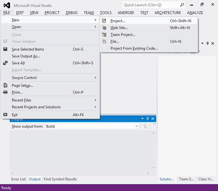
- Start Visual Studio. Select File->New->Project in the menu.
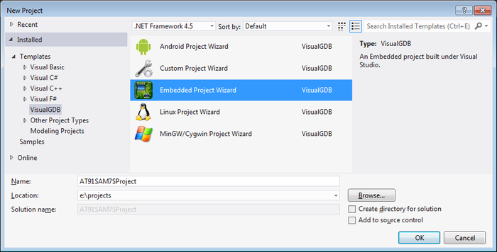
- Select VisualGDB -> Embedded Project Wizard.
Specify project directory and enter project name.
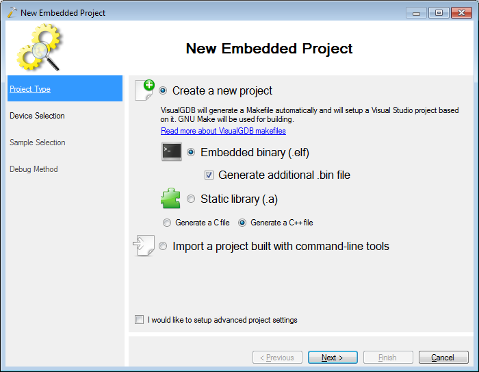
- Select “Embedded binary”. If you want to program your firmware using a third-party FLASH programming tool, it is recommended to enable the ‘create additional .bin file’ option.
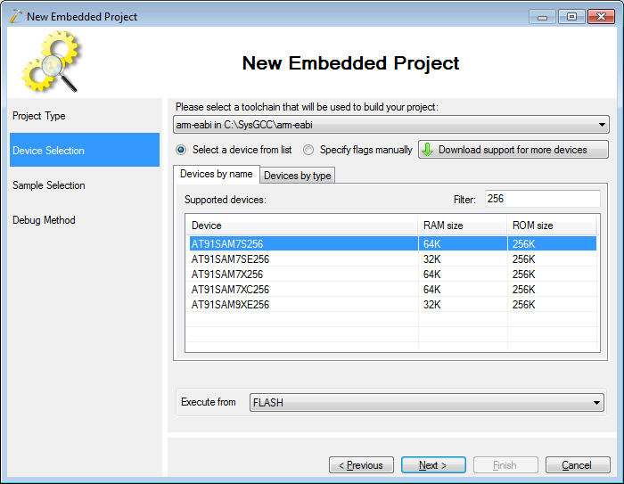
- Select the “arm-abi” toolchain. If it is missing, VisualGDB will automatically download and install it:
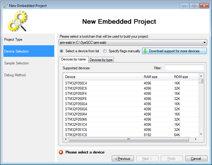
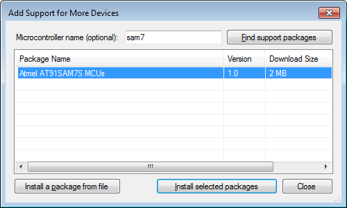
- If you don’t see AT91SAM7 devices in the device list, click “Download Support for more devices”, find “AT91SAM7S MCUs” and click “Install selected packages”:
- Now select your device from the device list. In this tutorial we will use AT91SAM7S256:
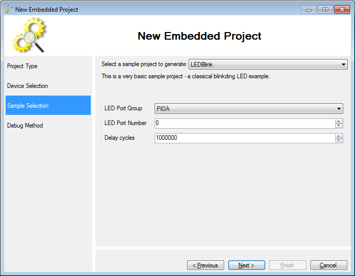
- On the next page select a sample to create. The LEDBlink is the simplest one. Alternatively VisualGDB can create projects for some samples provided by Atmel.
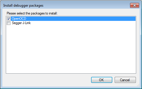
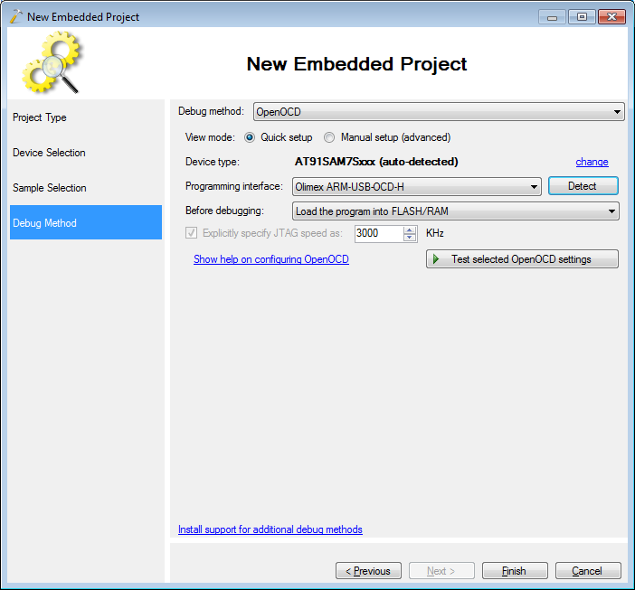
- The last page allows selecting the debug method. We will use the OpenOCD tool to debug the board using the Olimex ARM-USB-OCD-H programmer. If you have not installed it yet, click “Install support for additional debug methods”, select “OpenOCD” and press OK:
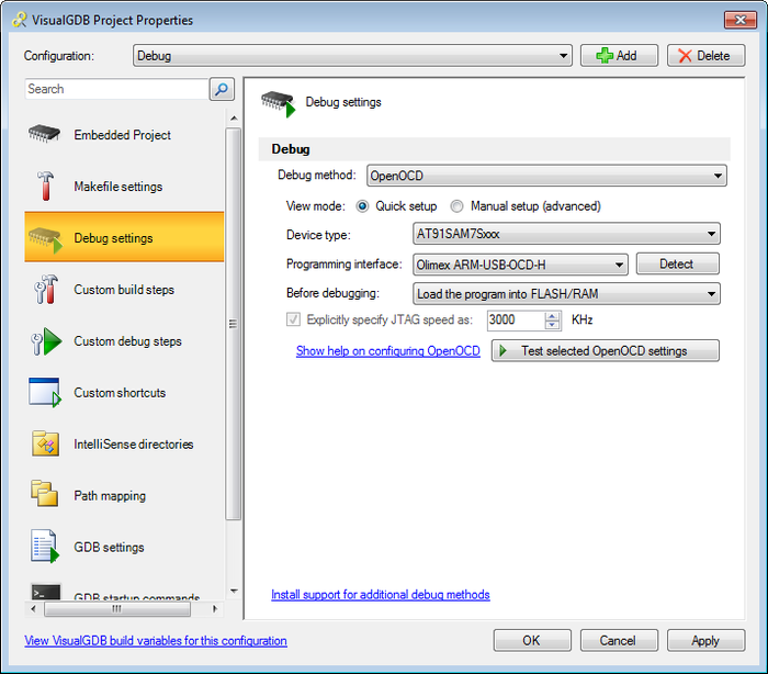
- On the debug method configuration page press the “Detect” button to automatically detect your JTAG programmer or select it from the list:
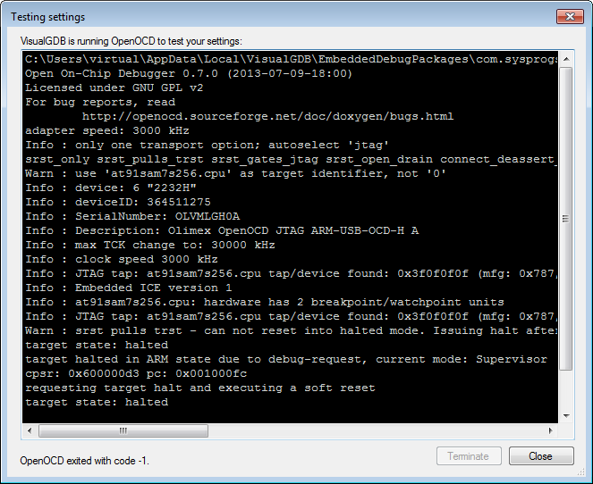
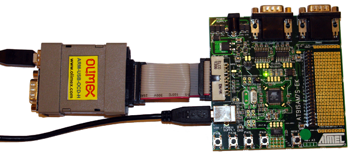
- Connect your JTAG programmer to the board, turn it on and press “Test selected OpenOCD settings”. If you don’t have the FTDI driver installed, VisualGDB will install it for you. The successful test results should look the following way:
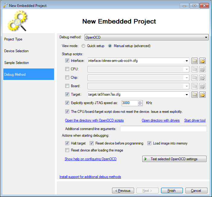
- If you want to customize the OpenOCD scripts and tweak various settings, you can switch to manual setup mode:
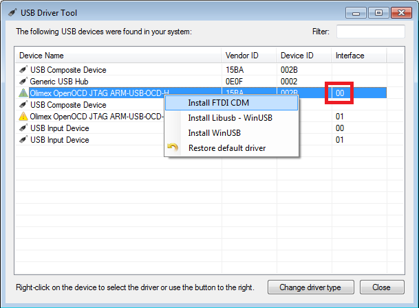
- If you experience driver issues, you can install the FTDI driver manually by clicking on “Start driver tool” and finding your device (select interface 0) in it:
- Once the debugger connection is tested, close the test window and press “Finish” to end the wizard. VisualGDB will generate a Visual Studio project for your device. Build it by pressing Ctrl-Shift-B:
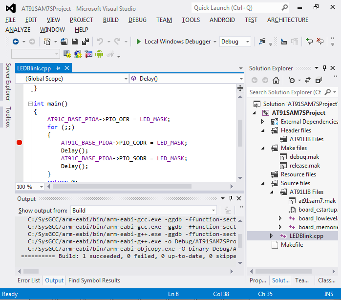
- Set a breakpoint on the line turning on the LED and press F5 to start debugging:
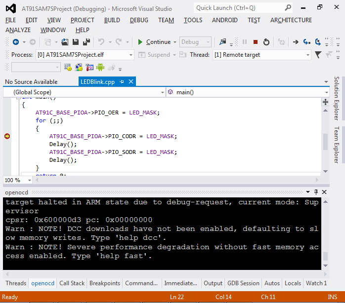
- Once the breakpoint is hit, press F10 to do a single step or F5 to run an iteration of the loop until the breakpoint hits again. Observe how the LED turns on and off:
- Press Shift-F5 to stop debugging. Right-click on your project in Solution Explorer and select VisualGDB Project Properties:
 You can use the Project Properties window to change a wide variety of settings related to building and debugging your project.


