Using the Serial Port on Teensy boards from Arduino code
This tutorial shows how to use the serial port on the Teensy boards to communicate with the Arduino code running on it. We will create a basic Teensy project with Visual Studio and modify it to input and output data via the USB serial port provided by the Teensy Arduino core.
Before you begin, follow our basic Teensy tutorial to get started with Teensy and VisualGDB.
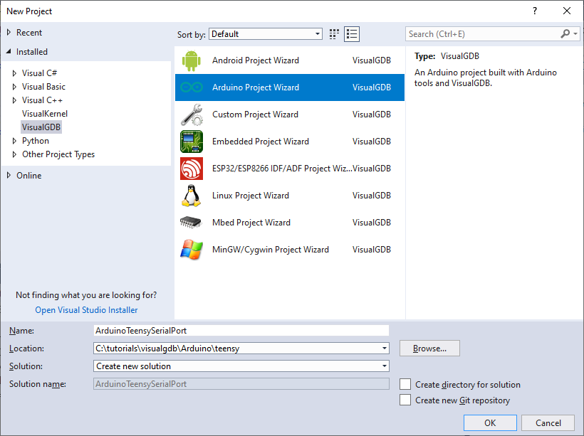
- Start Visual Studio and open the VisualGDB Arduino Project Wizard:
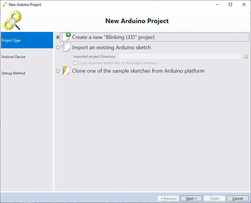
- On the first page of the wizard select Create a new “Blinking LED” project:
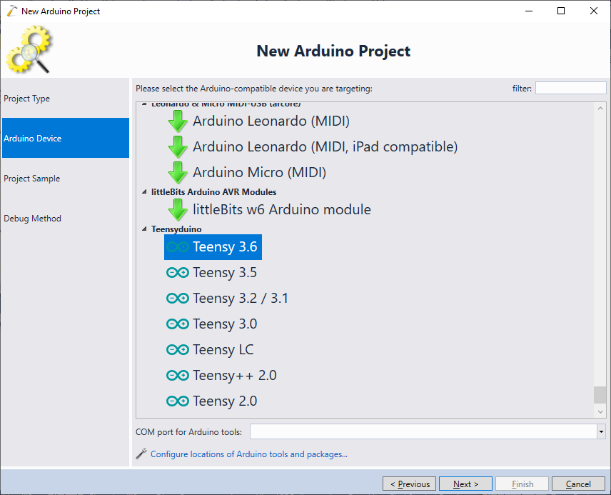
- On the next page select your Teensy board. If the Teensy targets do not appear, follow our basic Teensy tutorial to import the Teensy files into VisualGDB:
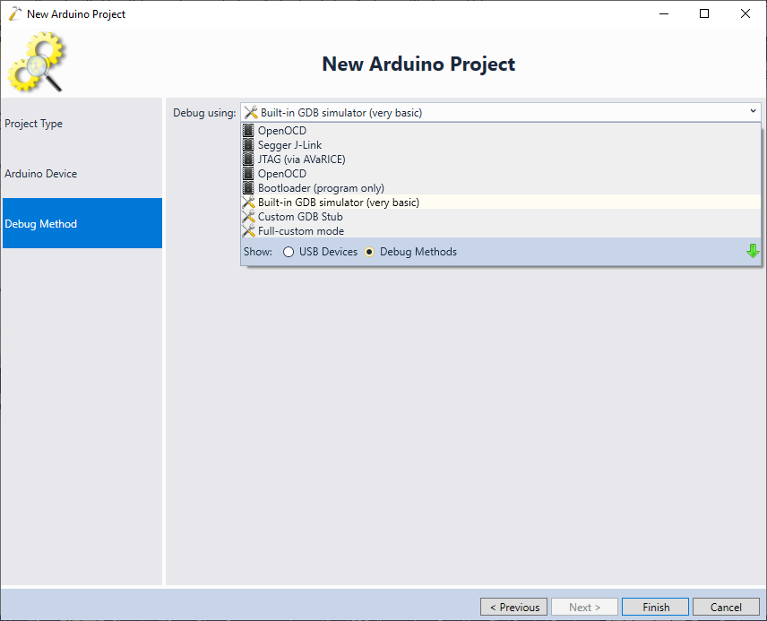
- As the Teensy boards to not support JTAG/SWD debugging, select “Debug Methods -> Built-in GDB Simulator” on the Debug Method page. This will allow continuing the wizard, although the simulator won’t be able to emulate the Teensy board:
- Press “Finish” to create the project. Once it is created and loaded, open VisualGDB Project Properties and locate the “USB Type” setting:
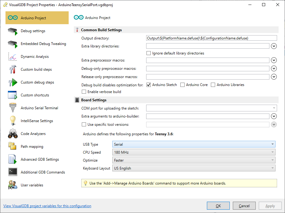 The Teensy board is capable of emulating numerous different USB peripherals and their combinations. In this tutorial we will only use the virtual serial port, so ensure “Serial” is selected as the USB type.
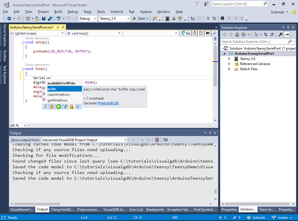
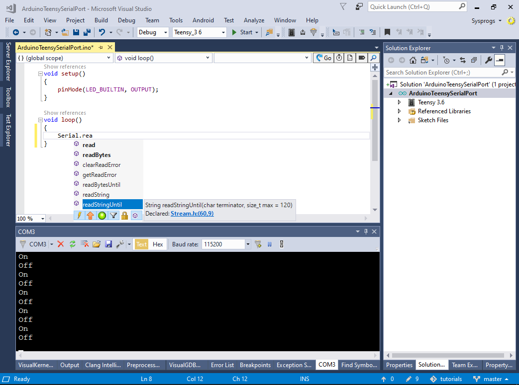
 - VisualGDB will automatically scan the code of the Teensy core and configure IntelliSense accordingly. E.g. it will suggest the available serial ports and their methods:
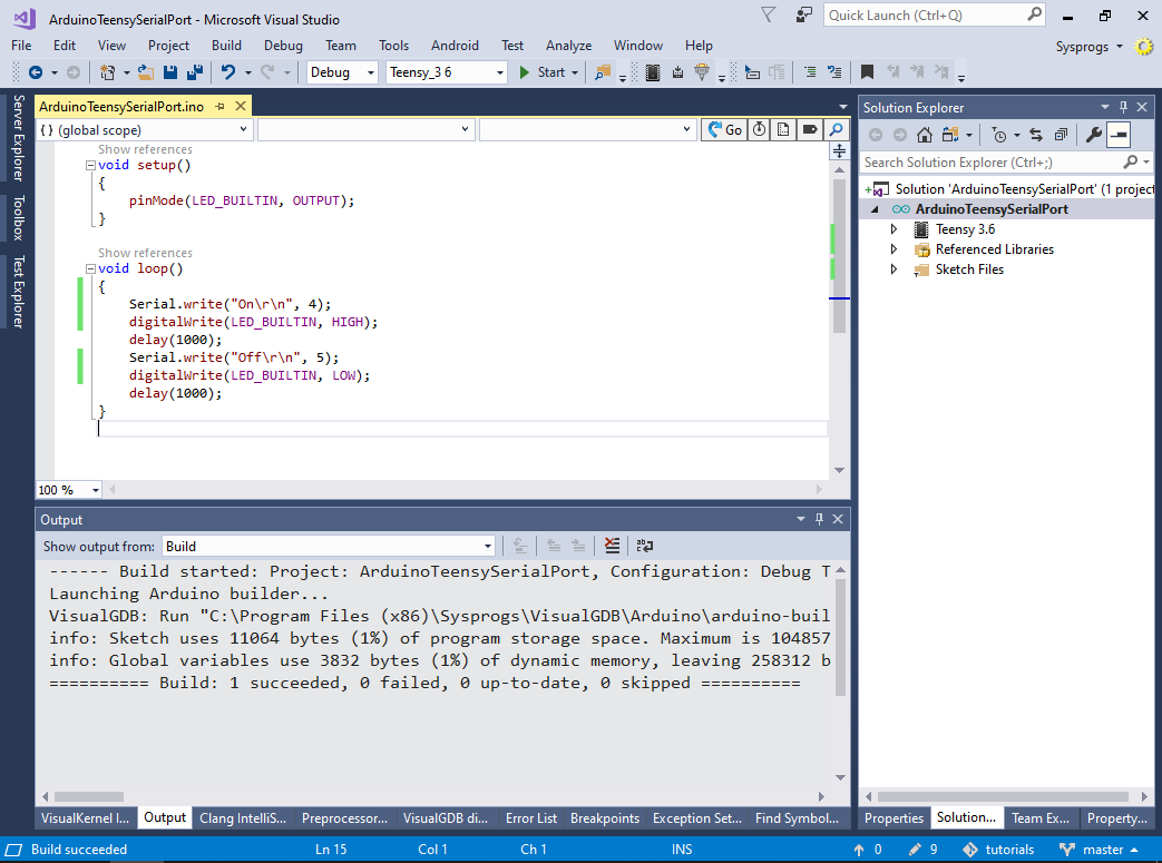
- We will now use the low-level write() method of the Serial object to output some text. Replace the loop() function with the code below:
void loop()
{
    Serial.write("On\r\n", 4);
    digitalWrite(LED_BUILTIN, HIGH);
    delay(1000);
    Serial.write("Off\r\n", 5);
    digitalWrite(LED_BUILTIN, LOW);
    delay(1000);
}
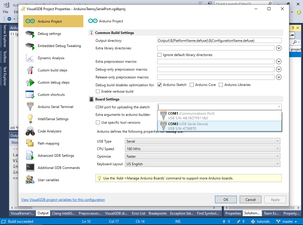
- Build the code and program it into the Teensy board by pressing the programming button (see the basic Teensy tutorial for more details). Once the programming is complete, the board will get recognized as a USB-based COM port. Open VisualGDB Project Properties and select the port in the “COM port for uploading the sketch” field:
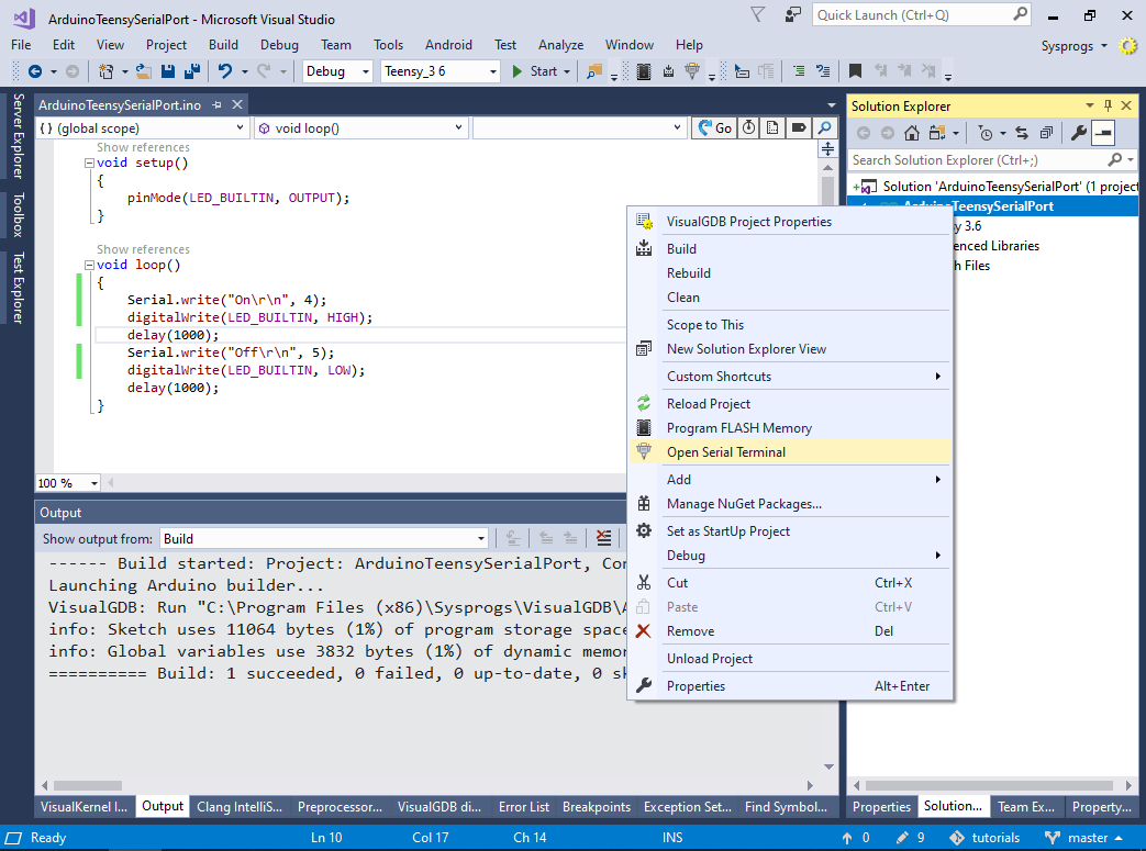
- Close VisualGDB Project Properties, right-click in Solution Explorer and select “Open Serial Terminal”:
- VisualGDB will open a terminal window showing the output from the loop() function:

- Now we will demonstrate some more high-level serial port API:
- The readStringUntil() method will be used to read the input line-by-line.
- The printf() method will be used to write formatted text output
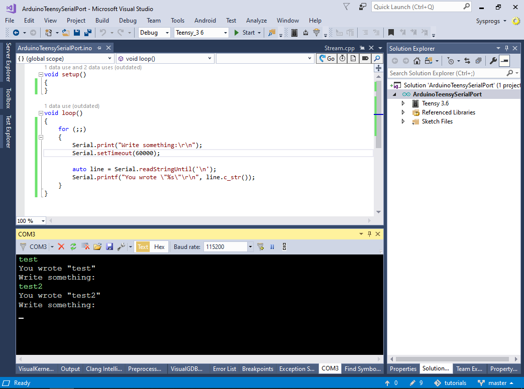
- Replace the contents of the loop() function with the code below:
        Serial.print("Write something:\r\n");
        auto line = Serial.readStringUntil('\n');
        Serial.printf("You wrote \"%s\"\r\n", line.c_str());
Then program the board and reconnect the serial terminal:
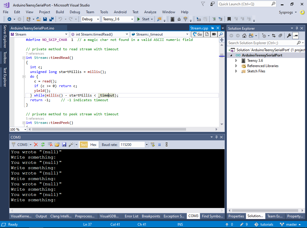
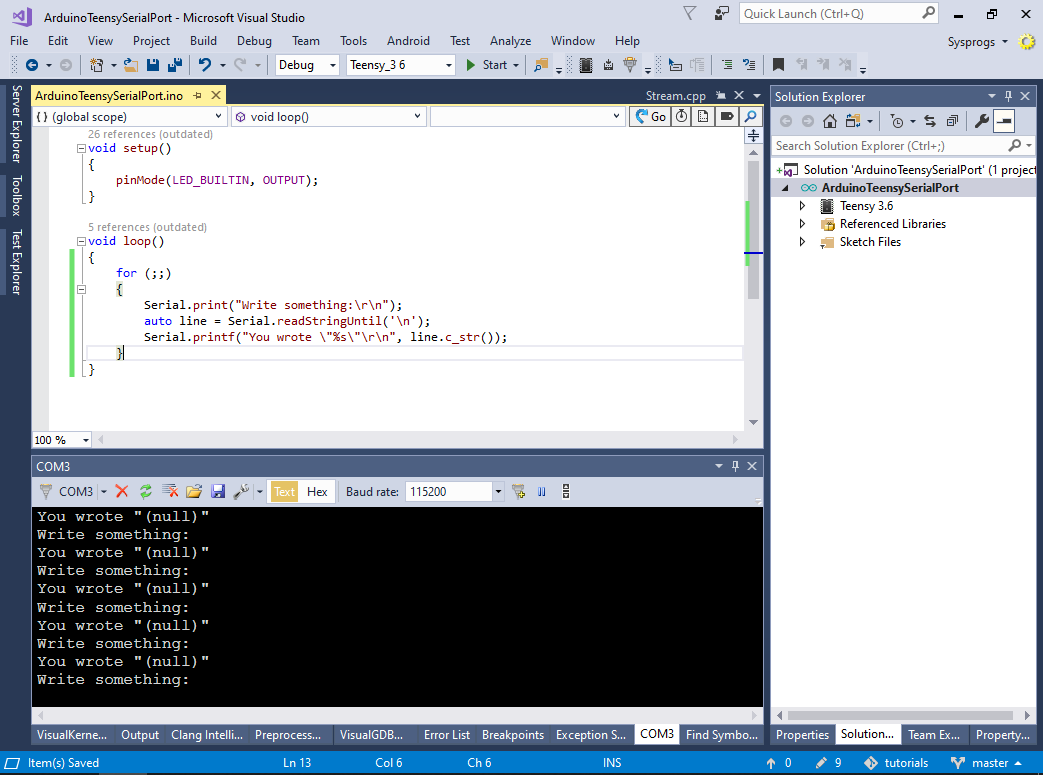 You will observe that the printf() method works as expected, however the readStringUntil() method times out.
 - The lack of a hardware debugging interface makes it harder to understand what is going on, so we will rely on VisualGDB’s code jumps to quickly navigate the function call chains:
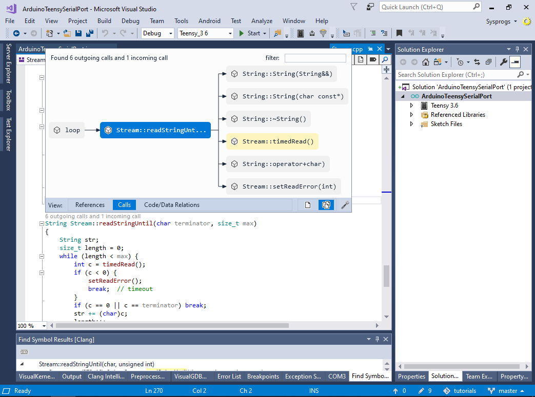
- Go to the timedRead() function and note code that checks the _timeout variable:
- Hover the mouse over the _timeout word and select “Code/Data Relations”. VisualGDB will immediately show that the timeout is set by the setTimeout() method and read by 4 other methods:
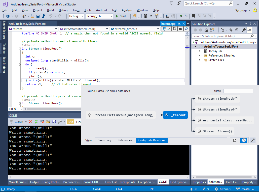
- Add a call to setTimeout() before calling readStringUntil(). The example will now work as expected, waiting for you to enter the entire line of text: