Programming the FLASH memory of i.MXRT devices with OpenOCD
This tutorial shows how to debug the i.MXRT devices and program their FLASH memory using OpenOCD. We will show how to create an OpenOCD script that will handle the resetting of the chip properly, and then clone the fsl_romapi example from the i.MXRT SDK and will change it into an OpenOCD plugin for writing the FLASH memory. The FLASH plugins are supported by the Sysprogs fork of OpenOCD.
In this tutorial we will use Visual Studio and VisualGDB to demonstrate everything, however the same steps will also work with any other environment that uses GCC and OpenOCD.
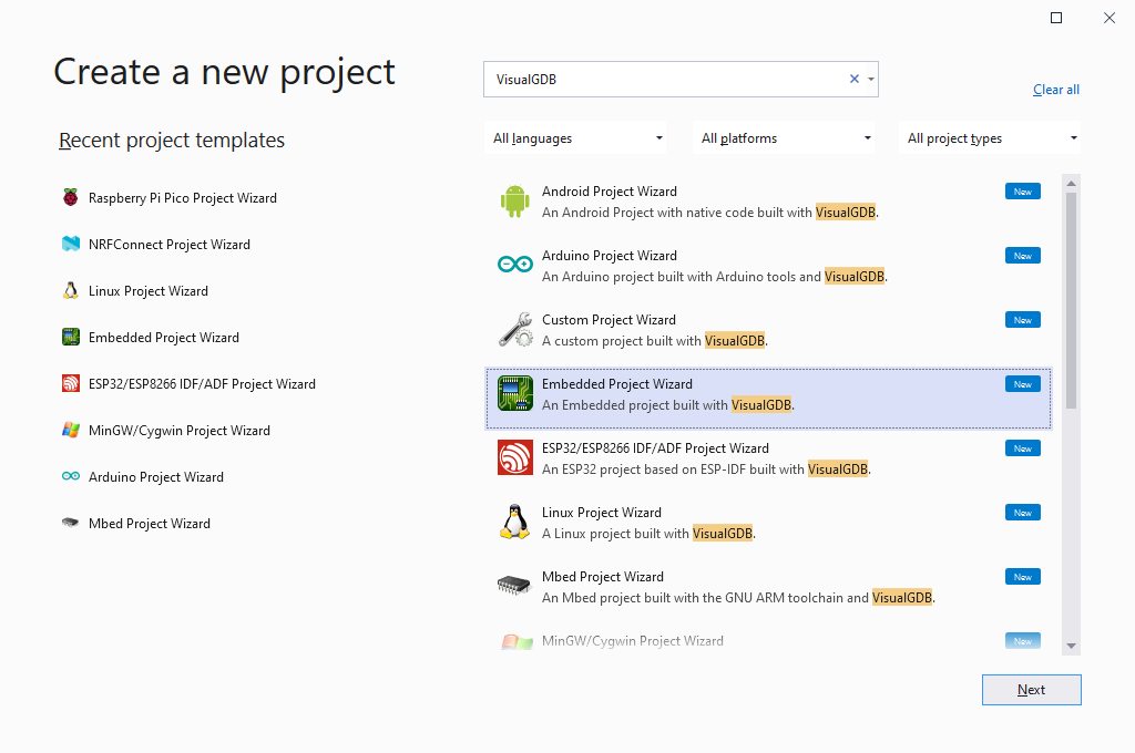
- Start Visual Studio and locate the VisualGDB Embedded Project Wizard:
- The first project we will create will be the fsl_romapi example showing how to use the i.MXRT ROM API to program the FLASH memory via FlexSPI. Pick the name and location for the project and click “Create”:

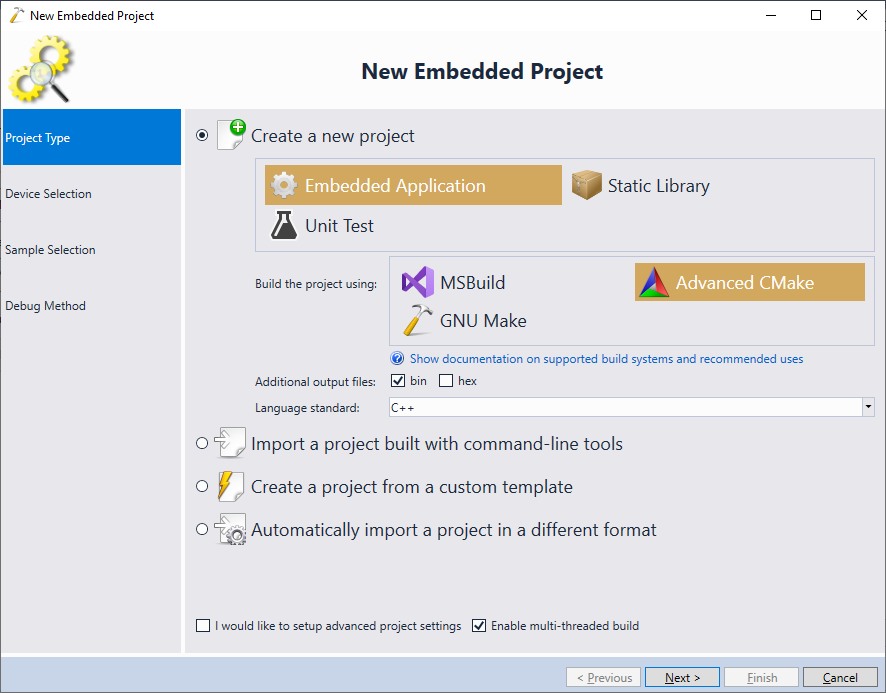
- On the first page of the VisualGDB-specific part of the wizard, select “Create a new project -> Embedded Application -> Advanced CMake”:
- If you have not created any i.MXRT projects with VisualGDB before, create an SDK for your device using the MCUXpresso SDK builder (make sure it targets the GNU tools), download it, extract it to a folder of your choice and click “Import an MCUXpresso SDK” to import it:

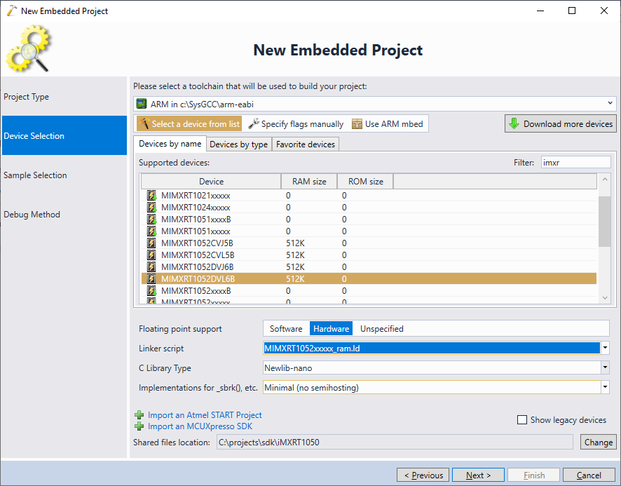
- Once the SDK is imported, you can pick your i.MXRT device sfrom the list. Make sure you select the RAM linker script:
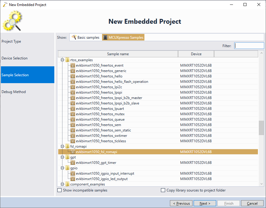
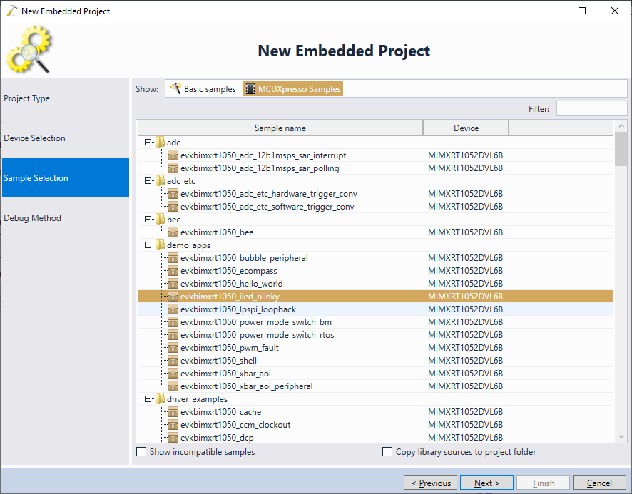
- On the Sample Selection page pick the fsl_romapi example and click “Next”:
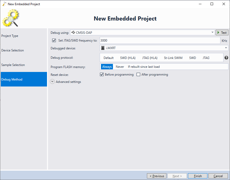
- Connect your board to the USB port. VisualGDB will automatically detect your debug interface and will suggest the matching OpenOCD configuration. The Sysprogs fork of OpenOCD already includes a basic configuration script for i.MXRT (not including the FLASH driver) that will be selected automatically. We will explain how to create your own script later in the tutorial:
- Once you click “Finish”, VisualGDB will generate the project based on the selected sample. However, the generated project will use the linker script from the example itself (MIMXRT1052xxxxx_flexspi_nor.ld) instead of the default RAM script. Reset is by clearing the “Linker Script” setting under VisualGDB Project Properties:
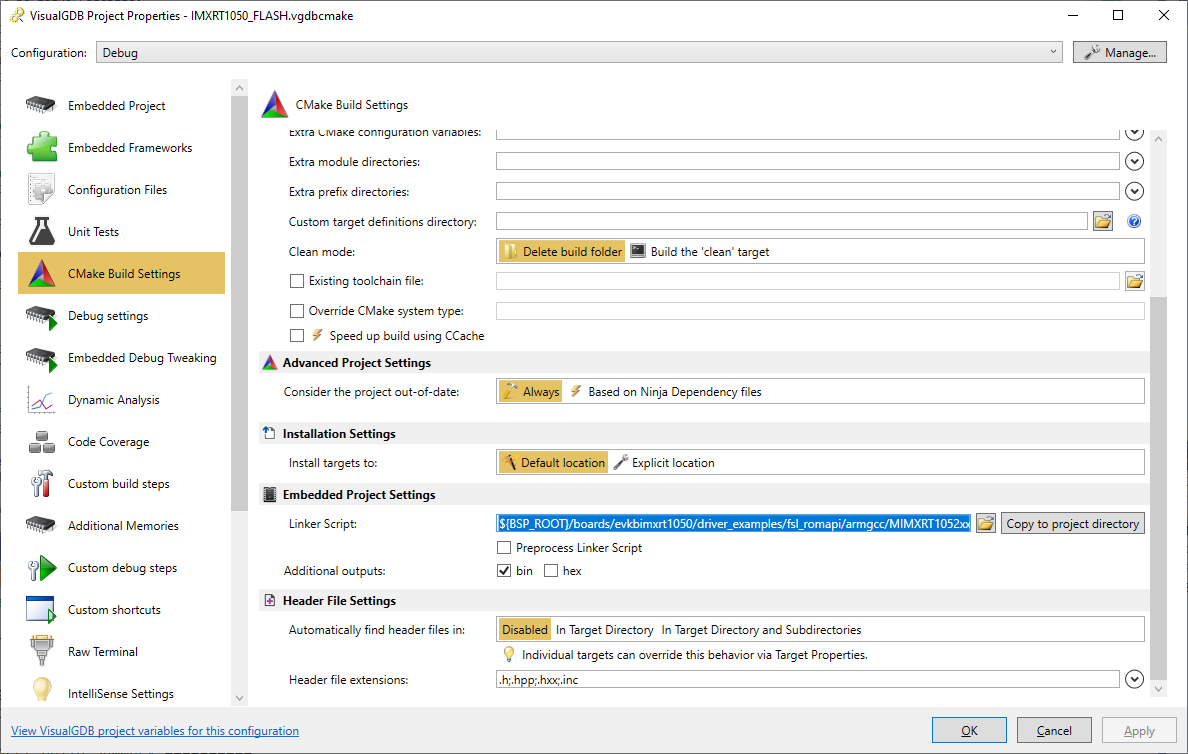
- This will revert to the MIMXRT1052xxxxx_ram.ld script and the project will now run directly from RAM:
- In order to debug the i.MXRT device with OpenOCD without programming the FLASH memory, you need to create a corresponding OpenOCD script. You can use our existing script for i.MXRT, or create a new one as shown below. First of all, the script needs to define a single ARM core debuggable via JTAG or SWD and specify the name/location of RAM that will be used as a scratch buffer:
swj_newdap $_CHIPNAME cpu -irlen 4 -expected-id $_CPU_SWD_TAPID
dap create $_CHIPNAME.dap -chain-position $_CHIPNAME.cpu

set _TARGETNAME $_CHIPNAME.cpu

target create $_TARGETNAME cortex_m -endian little -dap $_CHIPNAME.dap

$_TARGETNAME configure -work-area-phys 0x20200000 \
                       -work-area-size 0x4000 \
                       -work-area-backup 0
The _CPU_SWD_TAPID variable can be set arbitrarily. OpenOCD will display a warning if it doesn’t match the actual ID of the chip, so you can update it later based on that warning.
- The i.MXRT devices do not support automatic halting after a system-reset via the SVD interface (SRST), so instead they need to be reset using the ARM Cortex reset request:
cortex_m reset_config sysresetreq
reset_config none
The “reset_config none” line means that OpenOCD will not do a system-level reset itself and will only reset the core. However the “cortex_m reset_config sysresetreq” line makes sure that the core reset will actually reset the entire system.
- With the configuration shown above the “reset halt” and “reset init” commands will reset the chip right into the first instruction in the boot ROM, before the ROM gets a chance to initialize any peripherals. We can script OpenOCD to let the boot ROM run instead, and to wait until it jumps to the actual program. This can be done by examining the FLASH memory contents just before the reset (from the reset_init callback in Tcl) and setting a breakpoint at the entry point discovered from parsing the FLASH in the reset-deassert-post event handler. See our OpenOCD script for i.MXRT for the full implementation of this functionality.
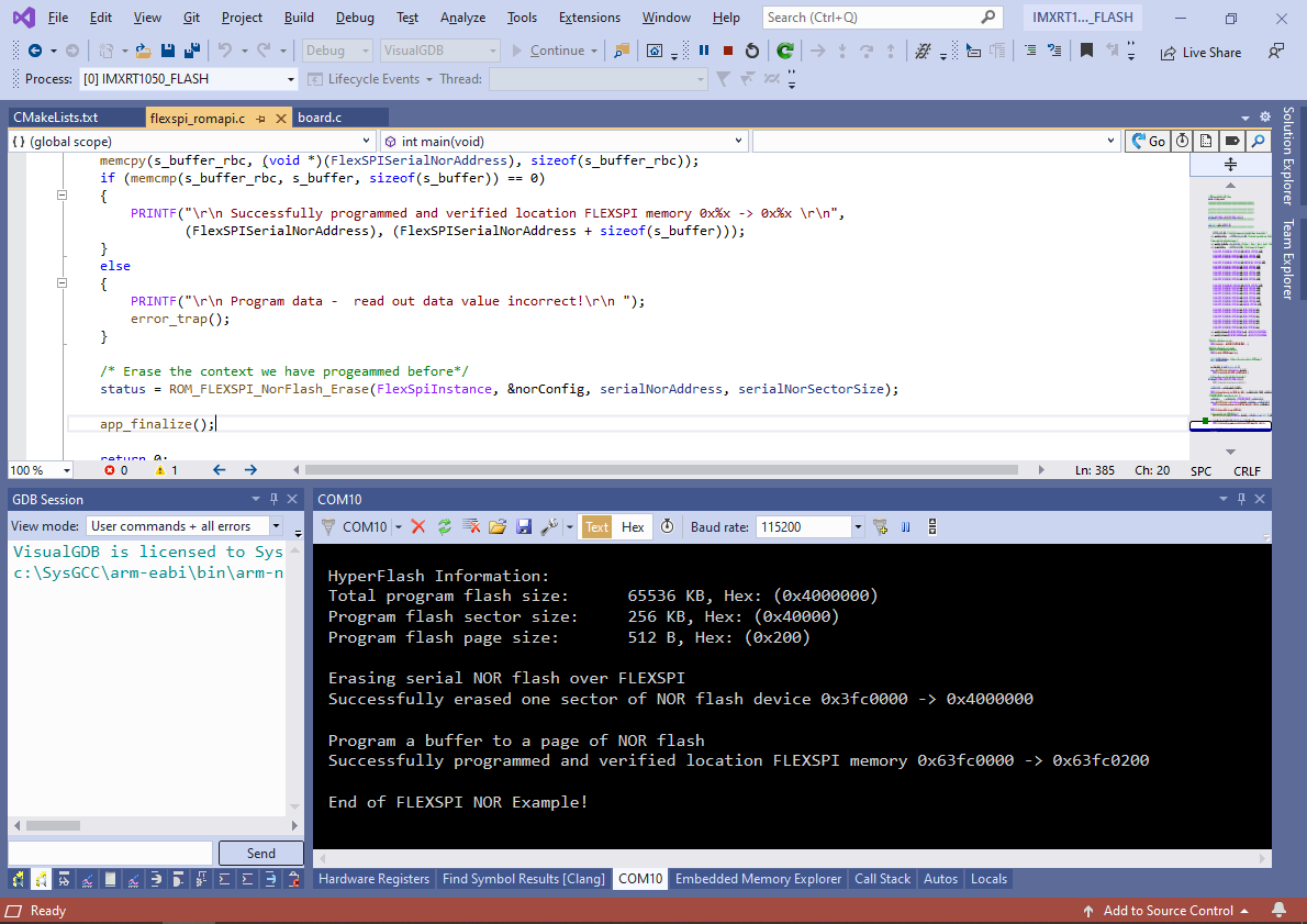
- Now we are ready to test out the FLASH programming example. Normally, it will print debugging output to the COM port connected to the on-board CMSIS-DAP debuggger. You can use the Raw Terminal window (requires VisualGDB Custom Edition) or any other terminal program to view it:

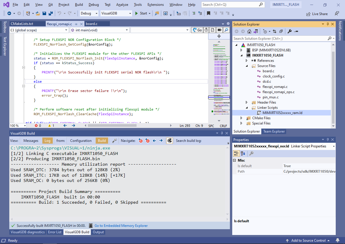
- Run the example and make sure it succeeds:
- The example project programs a fixed page of the FLASH memory with fixed contents. However, if we restructure it into having separate functions for erasing and programming the memory, the OpenOCD plugin interface will be able to call these functions to program meaningful FLASH memory contents. The restructuring involves the following steps:
- Add the common FLASH plugin sources to the project.
- Remove the calls to BOARD_ConfigMPU() and BOARD_BootClockRUN() as they are not required for programming the memory.
- Call FLEXSPI_NorFlash_GetConfig() and ROM_FLEXSPI_NorFlash_ClearCache() directly from main().
- Once FlexSPI has been initialized, call FLASHPlugin_InitDone(). This will signal to OpenOCD that the plugin has been initialized and is ready to run meaningful functions.
- Implement the FLASHPlugin_Probe(), FLASHPlugin_FindWorkArea(), FLASHPlugin_EraseSectors() and FLASHPlugin_DoProgramSync() functions using the functions from the sample project. See our sample i.MXRT1050 implementation for a ready-to-use example. We recommend chaning the main file extension to .cpp to avoid C/C++ conflicts.
- Create a FLASHPluginConfig.h file defining the MINIMUM_PROGRAMMED_BLOCK_SIZE macro. You can copy FLASH_xxx definitions from the original example.
- Optionally, call TestFLASHProgramming() from main() to test the programming logic in a debuggable environment.
You can find complete plugin implementations for the i.MXRT1050 and i.MXRT1064 devices in our GitHub repository.
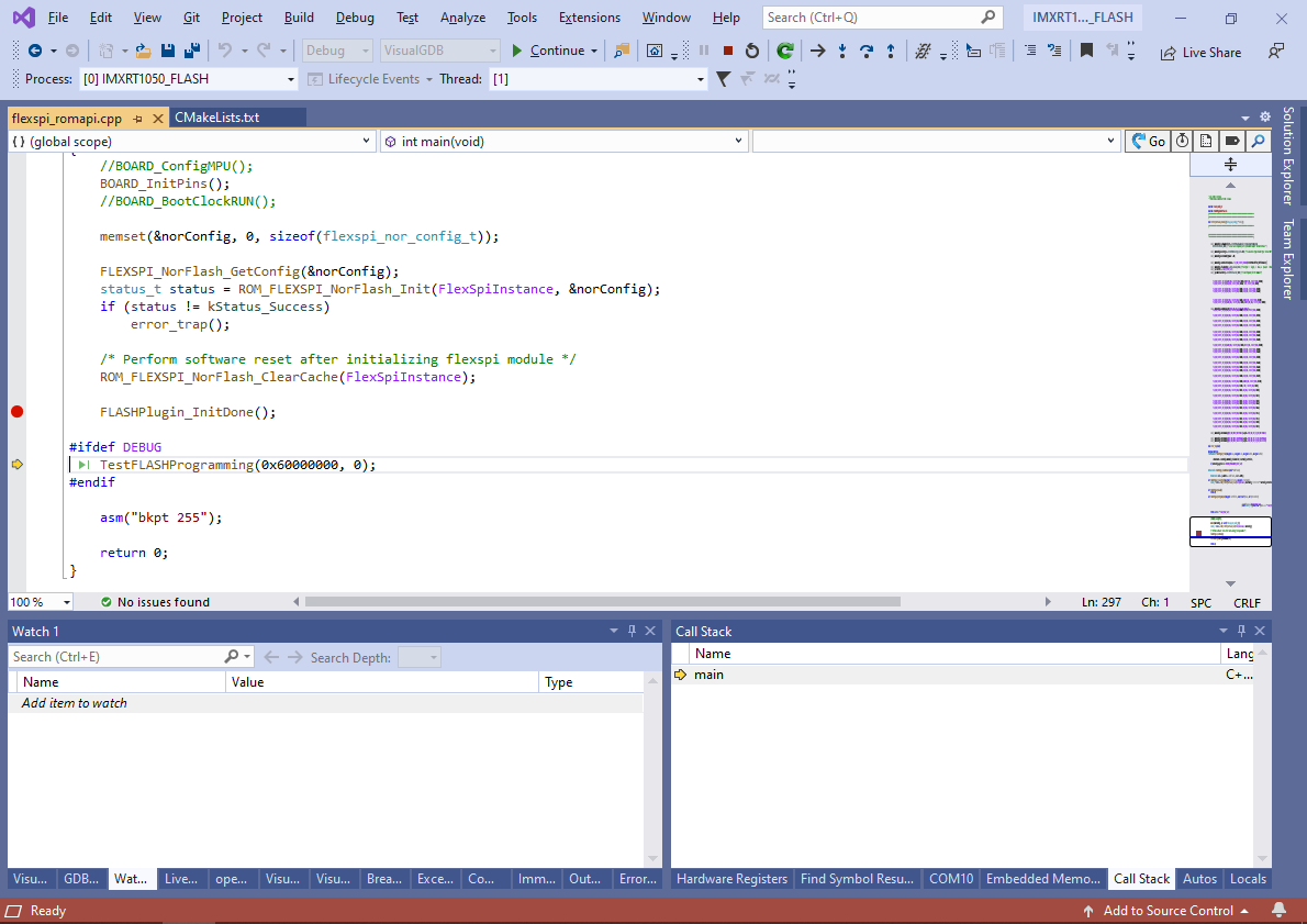
- After the restructuring is complete, try setting a breakpoint at the call to FLASHPlugin_InitDone() and debugging the project:
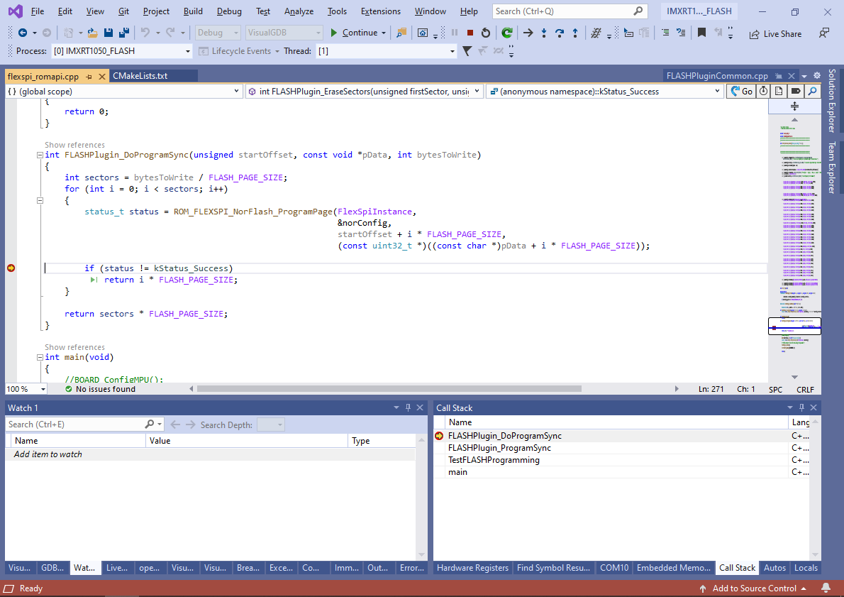
- The TestFLASHProgramming() function will automatically erase and program the first page of the FLASH memory using your implementations of FLASHPlugin_EraseSectors() and FLASHPlugin_DoProgramSync(). You can use it to verify that the memory gets programmed as expected:
- Now that the plugin is ready, open the VisualGDB Embedded Project Wizard again and create another project based on the iled_blinky example:
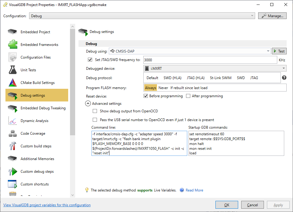
- This project will run from FLASH. In order to make OpenOCD program the FLASH memory, add the following command just before the “-c init” command:
flash bank imxrt plugin $FLASH_MEMORY_BASE 0 0 0 0 $(ProjectDir.forwardslashes)/IMXRT1050_FLASH
Then, copy the ELF file of the built FLASH plugin (e.g. <projects>\IMXRT1050_FLASH\build\VisualGDB\Debug\IMXRT1050_FLASH) to the directory of the new project:
- When you start a debug session now, OpenOCD will automatically do the following:
- Reset the device and let the boot ROM initialize the peripherals
- Load the FLASH plugin into the RAM
- Use the FLASH plugin to erase and program the memory (note that due to the way OpenOCD implements FLASH drivers, the plugin will get unloaded and loaded again between the erase and program operations).
- If the currently debugged project contained any RAM sections, OpenOCD would load them after unloading the FLASH plugin. In either case, the FLASH plugin will be completely unloaded before the application gets a chance to run and will never collide with it.
- Set the $pc register to the application’s entry point and let it run.
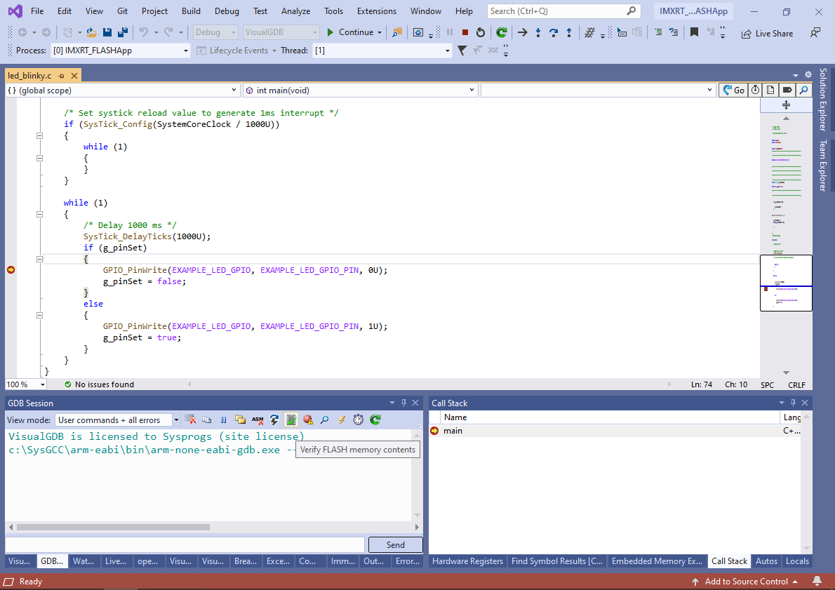
As a result, the application you are debugging will seamlessly get programmed into FLASH and you will be able to debug it. You can use the “Verify FLASH memory contents” button to ensure all sections have been programmed correctly: