Targeting ARM-based Renesas devices with Visual Studio
This tutorial shows how to use VisualGDB to create, build and debug a basic project for the ARM-based Renesas devices. We will use the EK-RA2E1 board featuring the R7FA2E1A92DFM microcontroller and will show how to change various parameters of the Renesas software framework and let VisualGDB regenerate the configuration files.
Before you begin, install VisualGDB 5.6R5 or later.
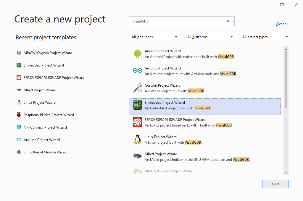
- Start Visual Studio and locate the VisualGDB Embedded Project Wizard:
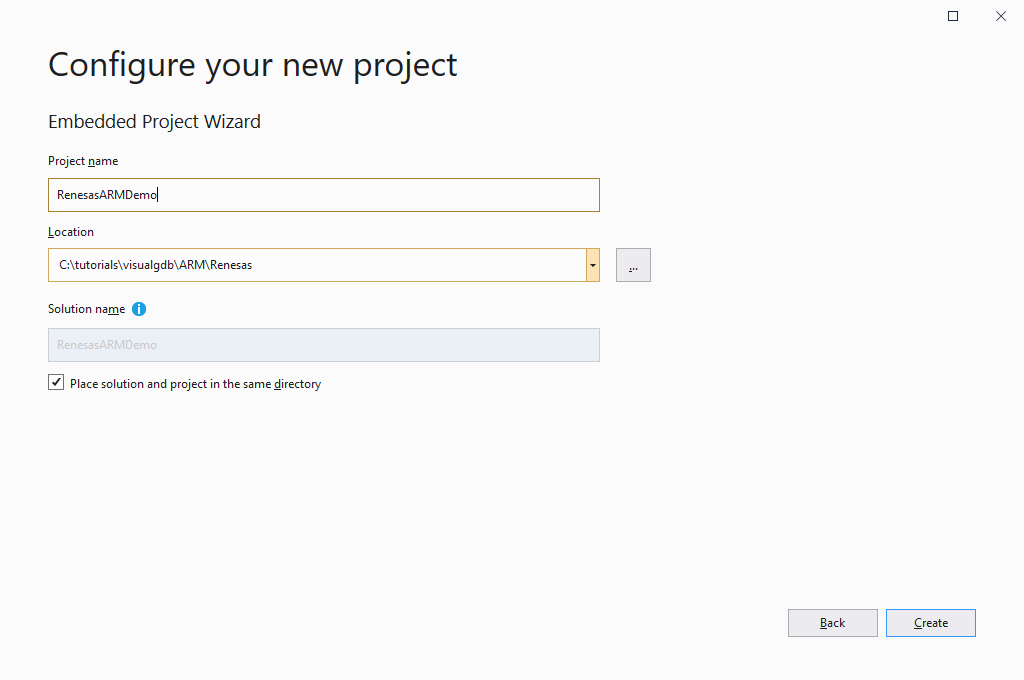
- Specify the name and location for your project:
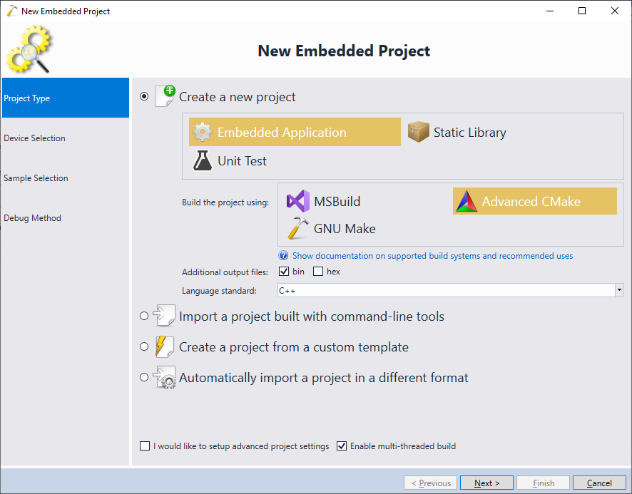
- Proceed with the default settings on the next page (Create a new project -> Embedded Application). As the Renesas software framework is relatively complex, we recommend using the Advanced CMake project subsystem that has been specifically optimized to handle frameworks of this scale:
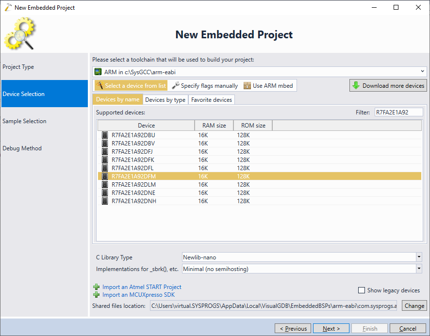
- On the next page pick the ARM toolchain and select your device from the list. If this is the first time you are creating a project for an ARM-based Renesas device, VisualGDB will suggest automatically installing the BSP:
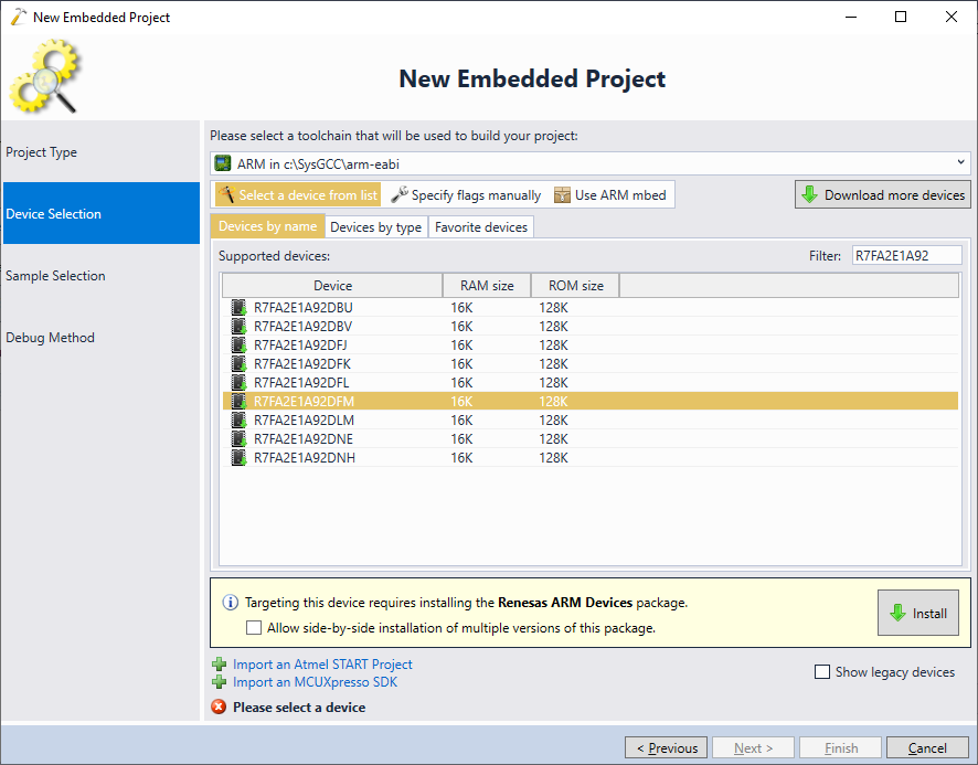
- Once the BSP has been installed, select the device you would like to target and press “Next”:
- The next page of the wizard allows selecting a sample project. The Renesas BSP contains 2 types of example projects:
- A very basic LEDBlink example that requires manually selecting the I/O port.
- The ‘blinky‘ samples taken from the original Renesas SDK. They can automatically pick up the LED locations for the development boards featuring the following devices:
- R7FA4W1AD2CNG
- R7FA2A1AB3CFM
- R7FA2E1A92DFM
- R7FA2L1AB2DFP
- R7FA4E10D2CFM
- R7FA4M1AB3CFP
- R7FA4M2AD3CFP
- R7FA4M3AF3CFB
- R7FA6E10F2CFP
- R7FA6M1AD3CFP
- R7FA6M2AF3CFB
- R7FA6M3AH3CFC
- R7FA6M4AF3CFB
- R7FA6M5BH3CFC
- R7FA6T1AD3CFP
If you are using one of the Renesas development boards with the devices listed above, select any of the blinky samples. If not, we advise starting with the basic LEDBlink example.
 Warning: if you create a blinky project for a device that is not listed above, you would need to copy (and edit) the LED definitions from one of the supported devices.
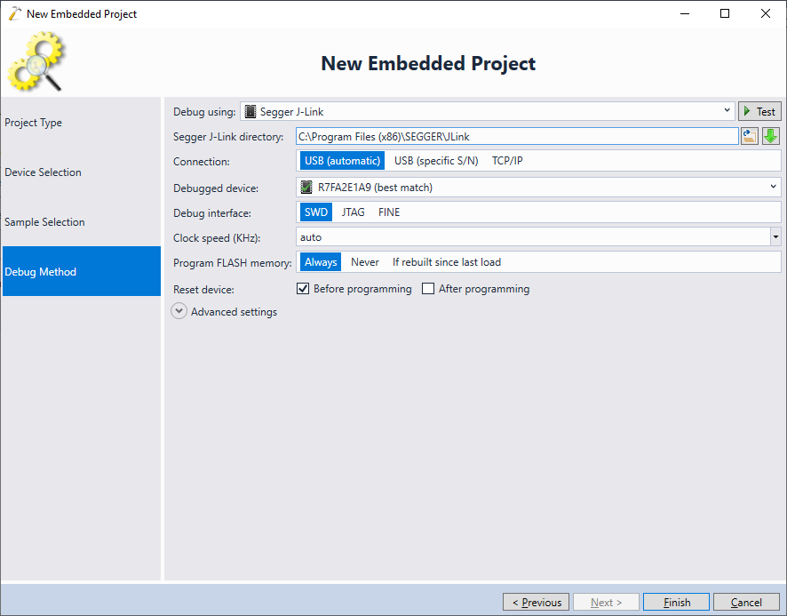
 - Connect your board to the USB port. Most Renesas development boards come with an on-board Segger J-Link, so VisualGDB will be able to automatically detect and configure it:
- Press “Finish” to create the project. Then build it by pressing Ctrl-Shift-B. The build should succeed out without any further modifications:
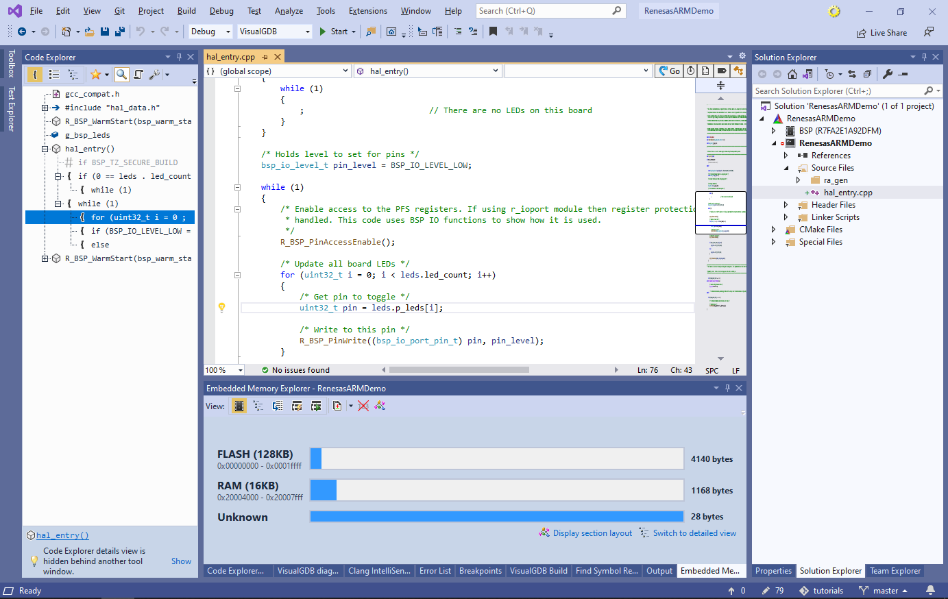 Note that the “unknown” section in the memory explorer corresponds to the ID_CODE region and can be ignored.
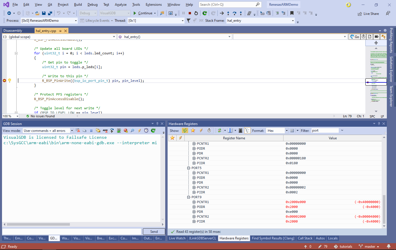
 - Set a breakpoint around the call to R_BSP_PinWrite() and press F5 to begin debugging. Once the breakpoint hits, try stepping over the call and observing how the corresponding PORT registers are changed:
 Warning: if the program doesn’t start correctly first time, try pressing the reset button in the GDB Session window, or starting the debug session again.
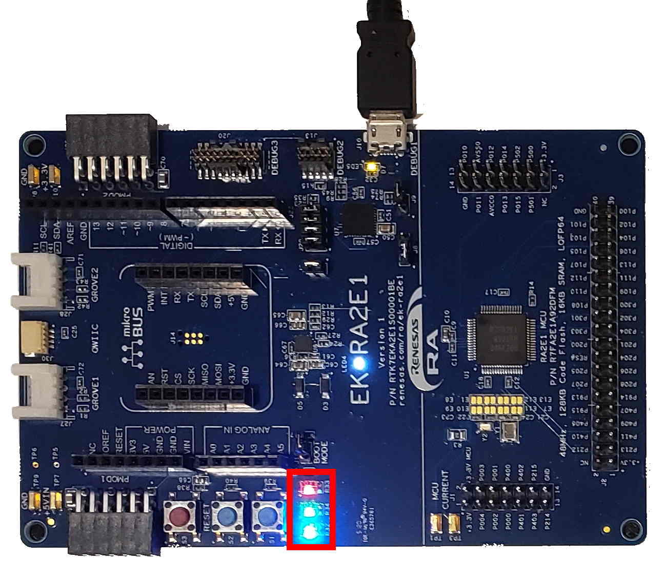
 - If you resume the program now, all the on-board LEDs should be continuously blinking:
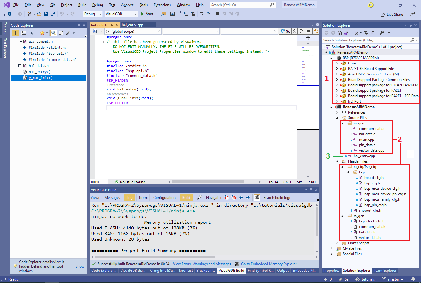
- Note that the Renesas projects consist of 3 key parts:
- Reusable components (e.g. I/O port driver, board support package) derived from the original Renesas SDK
- Configuration files generated based on the current project settings
- Actual project-specific code that can be edited
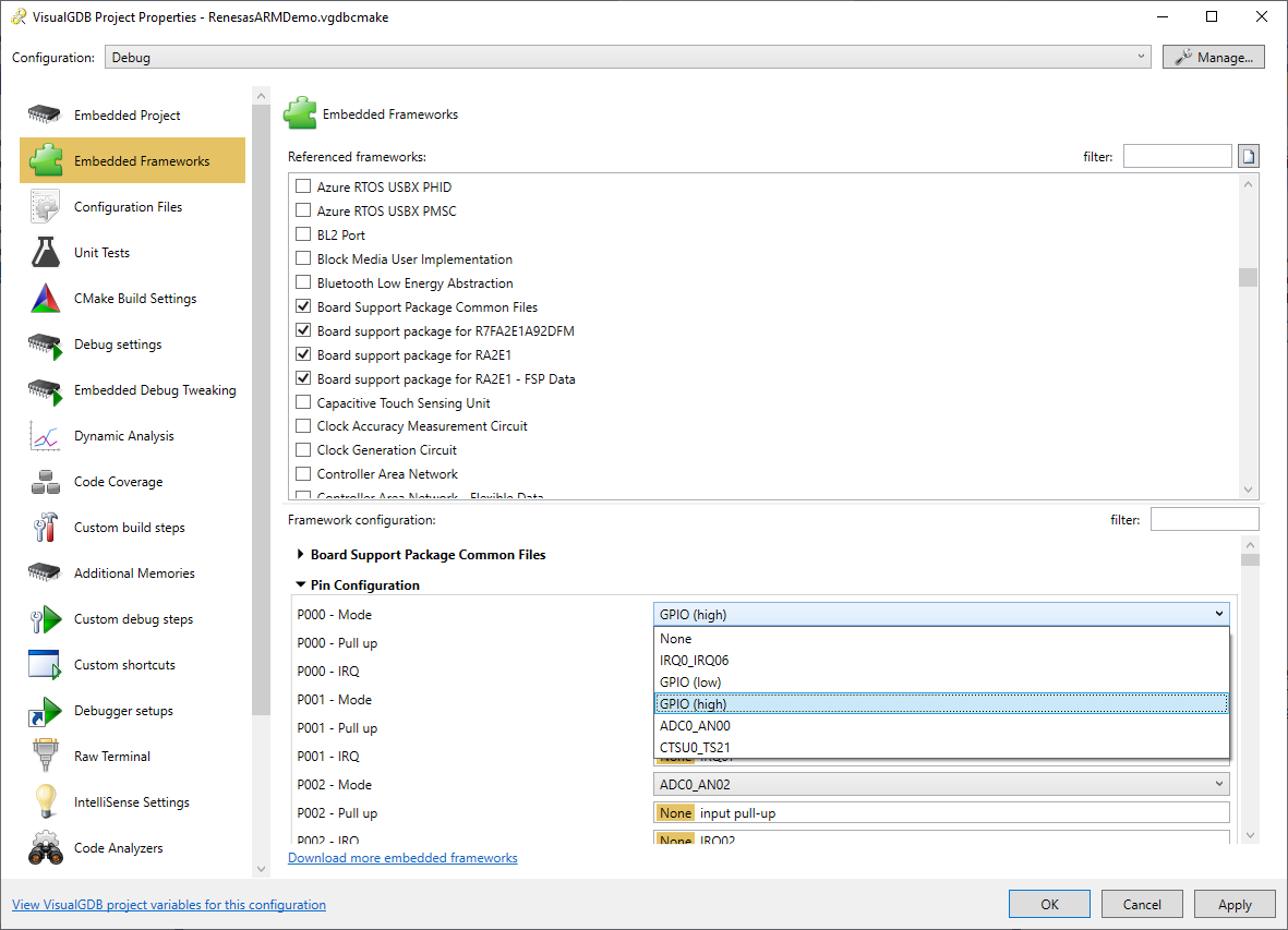
- Open the Embedded Frameworks page of VisualGDB Project Properties. It allows referencing various frameworks (derived from the components in the original SDK) and changing their configuration. Try changing the mode of the pin P000 to GPIO (high):
- VisualGDB will suggest automatically regenerating the affected configuration files (pin_data.c in this example). Proceed with the regeneration:
 Note how the initialization line corresponding to BSP_IO_PORT_00_PIN_00 got automatically updated.
 - Open the Embedded Frameworks page again and referenced the A/D Converter framework:
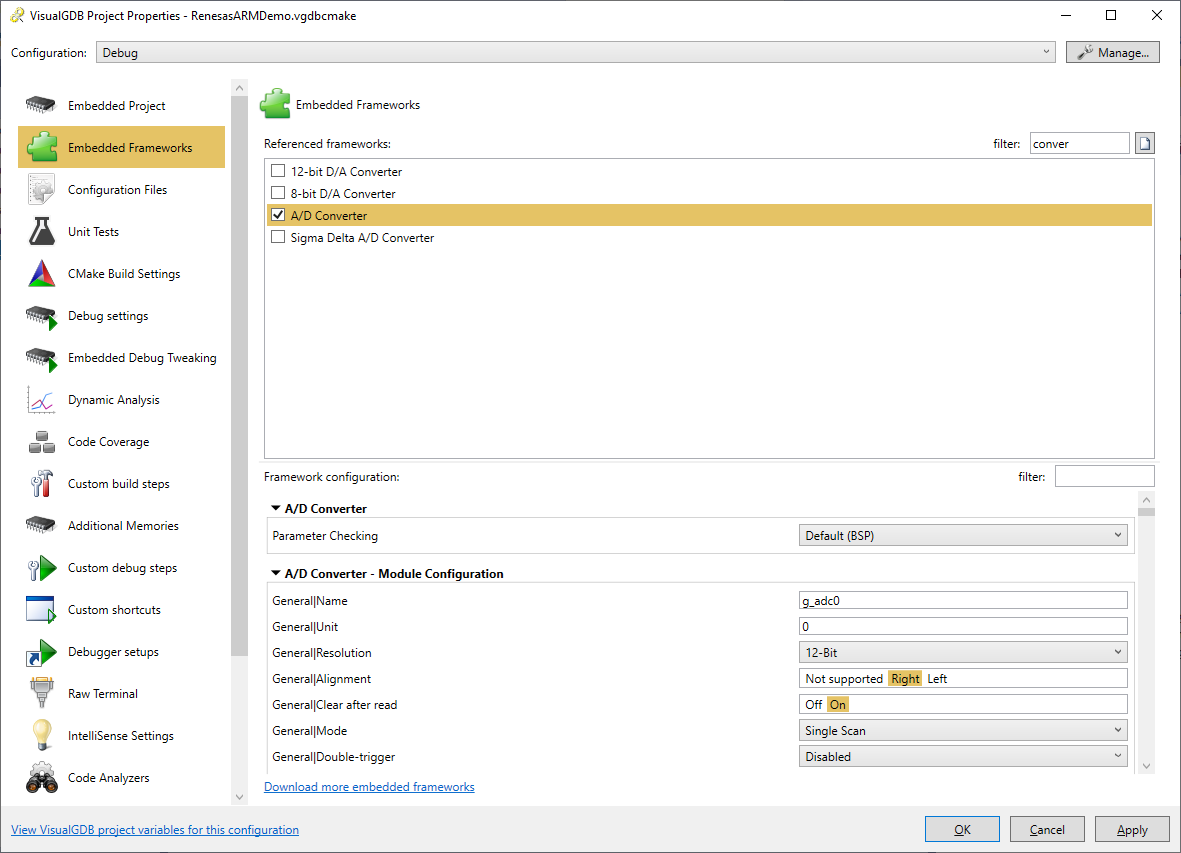 Once you press OK or Apply, VisualGDB will automatically insert the corresponding declarations and initialization code into the generated files.
Warning: as of BSP 3.3.0, only once instance of each peripheral (e.g. ADC0) is configurable via the Embedded Frameworks GUI. Additional instances can be configured by copying the initialization code manually.