Using the DMA Controller on STM32 Devices
This tutorial shows how to use the DMA controller on the STM32 devices, letting it perform background memory operations without consuming any CPU cycles. We will show how to use DMA to copy data between different buffers in RAM and also between RAM and the peripherals.
Before you begin, install VisualGDB 5.4 or later.
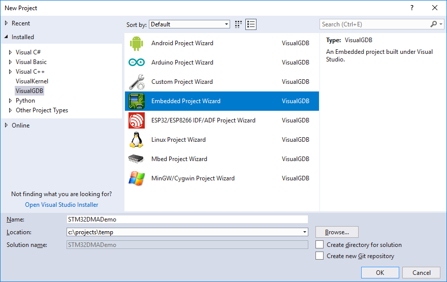
- Start Visual Studio and open the VisualGDB Embedded Project Wizard:
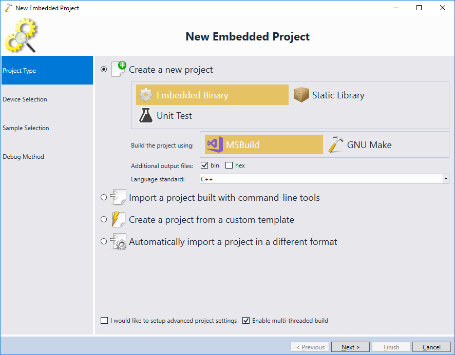
- On the first page of the wizard select “Embedded Binary -> MSBuild” and press “Next” to proceed to the next page:
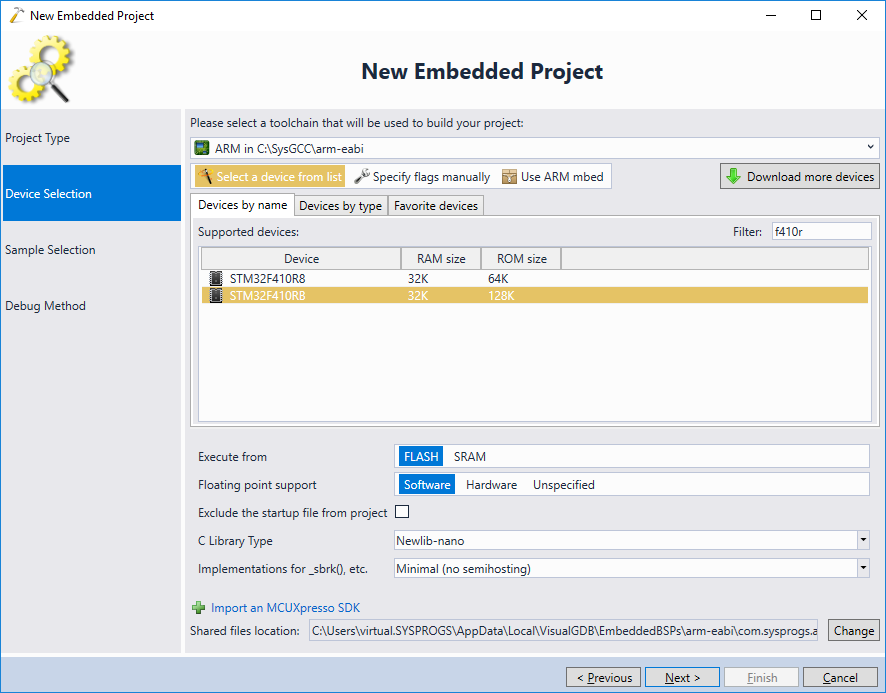
- On the Device Selection page pick the ARM toolchain and select your device from the list. In this tutorial we will use the Nucleo-F410RB board, so we select the STM32F410RB device, however the steps shown in this tutorial will work for most of the other STM32 devices as well:
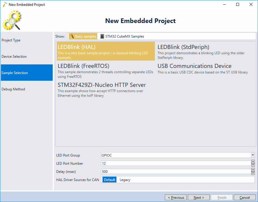
- In this tutorial we will add the DMA-related code from scratch, so select the most simple LEDBlink (HAL) tutorial on the next page:
- Finally, choose the debug settings that will work with your board. For most of the STM32 Discovery and Nucleo boards, simply connect the board to a USB port and VisualGDB will detect the settings automatically. Once the debug settings are configured, press “Finish” to generate a basic project.

- Once the project has been created, ensure you can debug and and take a note of the SystemCoreClock variable after the call to HAL_Init() returns:

- One last step before we begin experimenting with various DMA modes would be to enable the Chronometer on the Embedded Debug Tweaking page of VisualGDB Project Properties (requires Custom edition or higher). It will automatically record the CPU cycles elapsed between different debug events, making it easier to understand the timings:
 Warning: Ensure you enable the Chronometer for both Debug and Release configurations, as we will be using both of them in this tutorial.
 - Now we will create a basic program that will run 3 memory-intense operations:
- Fill a memory buffer with a sequence of numbers: Ni = i * 3.
- Copy the contents of the buffer to another buffer.
- Fill the third buffer with the first 1024 Fibonacci numbers.
Then we will and will then show how using the DMA improves its performance. Replace the main() function in your project with the following code:
#include <memory.h>

static int s_Buffer1[1024], s_Buffer2[1024], s_Buffer3[1024];

#define ARRAY_SIZE(x) (sizeof(x) / sizeof((x)[0]))

void __attribute__((noinline)) FillMemory()
{
    for (int i = 0; i < ARRAY_SIZE(s_Buffer1); i++)
        s_Buffer1[i] = i * 3;
}

void __attribute__((noinline)) CopyMemory()
{
    memcpy(s_Buffer2, s_Buffer1, sizeof(s_Buffer2));
}

void __attribute__((noinline)) CalculateFibonacci()
{
    s_Buffer3[0] = 0;
    s_Buffer3[1] = 1;

    for (int i = 2; i < ARRAY_SIZE(s_Buffer3); i++)
    {
        s_Buffer3[i] = s_Buffer3[i - 1] + s_Buffer3[i - 2];
    }
}

int main(void)
{
    HAL_Init();

    FillMemory();
    CopyMemory();
    CalculateFibonacci();

    volatile int x = s_Buffer2[4];
}
- To minimize the impact of unoptimized code on the measured numbers, switch the active configuration to Release, then set a breakpoint at the call to FillMemory() and start debugging:
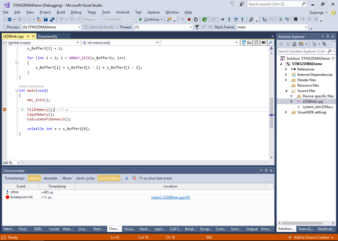
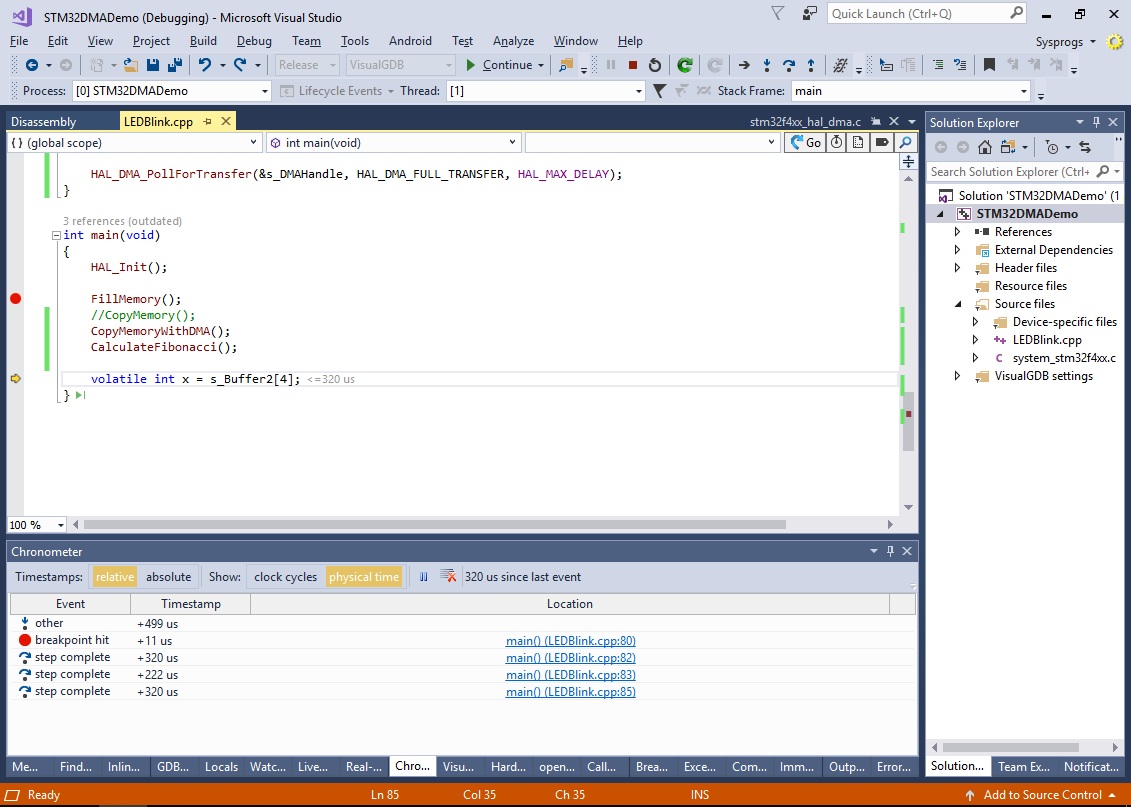
- Once the breakpoint hits, step over the FillMemory(), CopyMemory() and CalculateFibonacci() calls and check the Chronometer window for the timings:
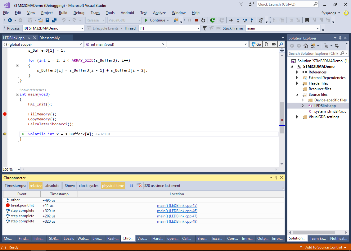 In this example, filling the first and the third buffer took the exactly the same time, while copying the first buffer to the second one took slightly less time:
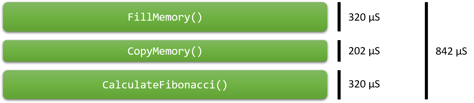
- While the DMA cannot be used to compute Fibonacci numbers, or initialize arrays with non-constant values, it can be used for copying data between 2 memory locations. We will now demonstrate this by replacing the CopyMemory() function with the following one:
#include <stm32f4xx_hal_dma.h>

static DMA_HandleTypeDef s_DMAHandle;

void __attribute__((noinline)) CopyMemoryWithDMA()
{
    s_DMAHandle.Instance = DMA2_Stream0;
    s_DMAHandle.Init.Channel = DMA_CHANNEL_0;

    s_DMAHandle.Init.Direction = DMA_MEMORY_TO_MEMORY;
    s_DMAHandle.Init.PeriphInc = DMA_PINC_ENABLE;
    s_DMAHandle.Init.MemInc = DMA_MINC_ENABLE;
    s_DMAHandle.Init.Mode = DMA_NORMAL;
    s_DMAHandle.Init.Priority = DMA_PRIORITY_VERY_HIGH;

    s_DMAHandle.Init.PeriphDataAlignment = DMA_PDATAALIGN_WORD;
    s_DMAHandle.Init.MemDataAlignment = DMA_MDATAALIGN_WORD;

    s_DMAHandle.Init.FIFOMode = DMA_FIFOMODE_ENABLE;
    s_DMAHandle.Init.FIFOThreshold = DMA_FIFO_THRESHOLD_HALFFULL;

    __DMA2_CLK_ENABLE();

    HAL_StatusTypeDef status = HAL_DMA_Init(&s_DMAHandle);
    if (status != HAL_OK)
        asm("bkpt 255");

    status = HAL_DMA_Start(&s_DMAHandle, (uint32_t)s_Buffer1, (uint32_t)s_Buffer2, sizeof(s_Buffer1) / sizeof(s_Buffer1[0]));
    if (status != HAL_OK)
        asm("bkpt 255");

    HAL_DMA_PollForTransfer(&s_DMAHandle, HAL_DMA_FULL_TRANSFER, HAL_MAX_DELAY);
}
The function above enables the DMA controller #2 (according to the STM32F410RB documentation, DMA#1 cannot be used for memory-to-memory transfers), and performs a single memory-to-memory transfer operation between s_Buffer1 and s_Buffer2.
- Run the new program and step over the function calls in main() to obtain the updated timings:
 Using DMA instead actually required more time than calling memcpy(), due to the initial setup (20 uS extra), however the CPU spent most of that time looping inside HAL_DMA_PollForTransfer() waiting for the DMA transfer to finish.
 - As the DMA transfers do not actually involve the CPU, we can easily change the program to compute the Fibonacci numbers in parallel with the DMA transfer:
    status = HAL_DMA_Start(&s_DMAHandle, (uint32_t)s_Buffer1, (uint32_t)s_Buffer2, sizeof(s_Buffer1) / 4);
    if (status != HAL_OK)
        asm("bkpt 255");

    CalculateFibonacci();

    HAL_DMA_PollForTransfer(&s_DMAHandle, HAL_DMA_FULL_TRANSFER, HAL_MAX_DELAY);
- Run the modified version of the program and observe the new timings:
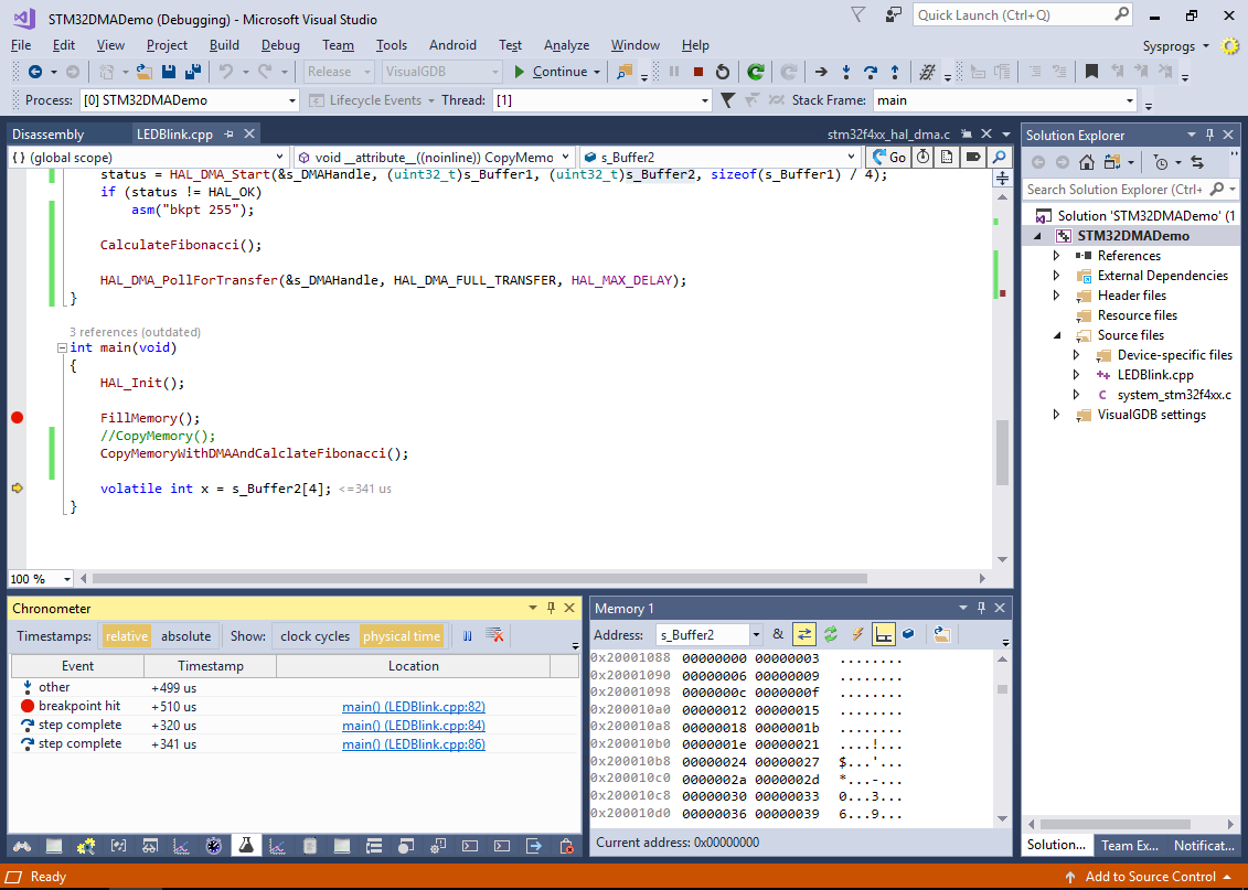
- Now the DMA operation ran in parallel with the CalculateFibonacci() function, reducing the overall program time by 21%:

- The DMA can be especially useful to optimize data transfers between the memory and various on-chip peripherals. E.g. we can modify the example above to output the contents of s_Buffer1 via the UART interface. Before we can do that, add the following function to your program to initialize the on-board UART peripheral:
#include <stm32f4xx_hal_uart.h>
static UART_HandleTypeDef s_UARTHandle;

static void SetupUART()
{
    __USART2_CLK_ENABLE();
    s_UARTHandle.Instance = USART2;

    s_UARTHandle.Init.BaudRate = 115200;
    s_UARTHandle.Init.WordLength = UART_WORDLENGTH_8B;
    s_UARTHandle.Init.StopBits = UART_STOPBITS_1;
    s_UARTHandle.Init.Parity = UART_PARITY_NONE;
    s_UARTHandle.Init.HwFlowCtl = UART_HWCONTROL_NONE;
    s_UARTHandle.Init.Mode = UART_MODE_TX_RX;
    s_UARTHandle.Init.OverSampling = UART_OVERSAMPLING_16;

    if (HAL_UART_Init(&s_UARTHandle) != HAL_OK)
        asm("bkpt 255");

    GPIO_InitTypeDef GPIO_InitStruct;
    __GPIOA_CLK_ENABLE();

    GPIO_InitStruct.Pin = GPIO_PIN_2;
    GPIO_InitStruct.Mode = GPIO_MODE_AF_PP;
    GPIO_InitStruct.Pull = GPIO_PULLUP;
    GPIO_InitStruct.Speed = GPIO_SPEED_FAST;
    GPIO_InitStruct.Alternate = GPIO_AF7_USART2;

    HAL_GPIO_Init(GPIOA, &GPIO_InitStruct);

    GPIO_InitStruct.Pin = GPIO_PIN_3;
    GPIO_InitStruct.Alternate = GPIO_AF7_USART2;

    HAL_GPIO_Init(GPIOA, &GPIO_InitStruct);
}
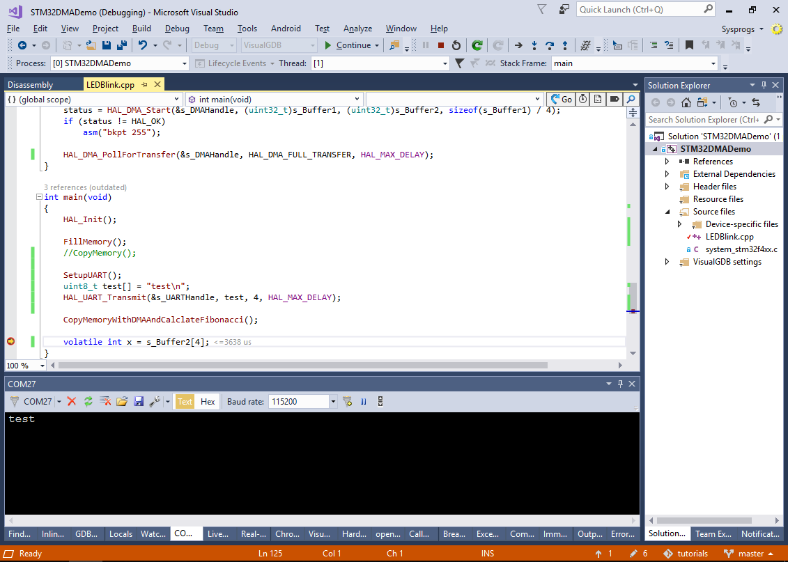
Then call it from main() and try outputting a test string by calling HAL_UART_Transmit():
    SetupUART();
    uint8_t test[] = "test\n";
    HAL_UART_Transmit(&s_UARTHandle, test, 4, HAL_MAX_DELAY);
Note that if you are using a different board than Nucleo-STM32F410RB, you may need to use a different UART (the one that is actually connected to the on-board ST-Link’s COM port) and different GPIO pins. You can find out the UART/GPIO configuration for your board by cloning one of the ST’s UART examples via the VisualGDB Embedded Project Wizard.
- Verify that the “test” output is printed to the COM port:
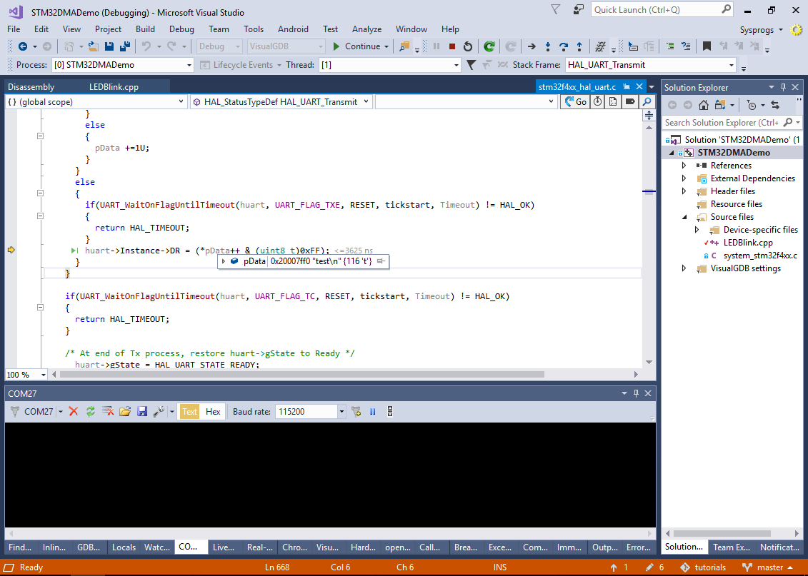
- If you step into the HAL_UART_Transmit() function, you will see that the data is sent to the UART peripheral by writing it byte-by-byte into the UART2->DR register:
- The DMA could do exactly that – copy a given buffer to the UART1->DR register byte-by-byte, although there would be several important differences compared to the memory-to-memory operation:
- We cannot use any arbitrary DMA controller. Instead, we need to pick the controller, stream and channel that are connected to the UART2 TX function. This will ensure that the DMA controller will not start transferring another byte until the UART controller is ready to accept it (i.e. has finished physically transmitting the previous one).
- The DMA mode will need to be changed from DMA_MEMORY_TO_MEMORY to DMA_MEMORY_TO_PERIPH.
- Unlike the memory-to-memory transfer, where we need to move the write pointer after each transferred word (to avoid overwriting the previous one), the memory-to-UART transfers should always end up at the same address (address of UART1->DR). This is achieved by changing DMA_PINC_ENABLE to DMA_PINC_DISABLE.
- Because the UART transfers one byte at a time, both peripheral and memory data alignment need to be set at BYTE instead of WORD.
You can find out the DMA stream and channel connected to the UART peripheral in the DMAx request mapping section of your STM32 device’s reference manual (not datasheet):
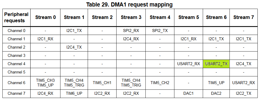
The updated CopyMemoryWithDMA() function outputing the buffer contents to UART will look as follows:
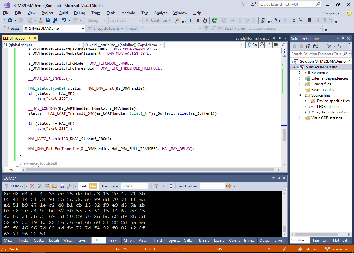
void __attribute__((noinline)) CopyMemoryWithDMAAndCalclateFibonacci()
{
    s_DMAHandle.Instance = DMA1_Stream6;
    s_DMAHandle.Init.Channel = DMA_CHANNEL_4;

    s_DMAHandle.Init.Direction = DMA_MEMORY_TO_PERIPH;
    s_DMAHandle.Init.PeriphInc = DMA_PINC_DISABLE;
    s_DMAHandle.Init.MemInc = DMA_MINC_ENABLE;
    s_DMAHandle.Init.Mode = DMA_NORMAL;
    s_DMAHandle.Init.Priority = DMA_PRIORITY_VERY_HIGH;

    s_DMAHandle.Init.PeriphDataAlignment = DMA_PDATAALIGN_BYTE;
    s_DMAHandle.Init.MemDataAlignment = DMA_MDATAALIGN_BYTE;

    s_DMAHandle.Init.FIFOMode = DMA_FIFOMODE_ENABLE;
    s_DMAHandle.Init.FIFOThreshold = DMA_FIFO_THRESHOLD_HALFFULL;

    __DMA1_CLK_ENABLE();

    HAL_StatusTypeDef status = HAL_DMA_Init(&s_DMAHandle);
    if (status != HAL_OK)
        asm("bkpt 255");

    status = HAL_DMA_Start(&s_DMAHandle, (uint32_t)s_Buffer1, (uint32_t)&USART2->DR, sizeof(s_Buffer1));
    if (status != HAL_OK)
        asm("bkpt 255");

    SET_BIT(USART2->CR3, USART_CR3_DMAT);
    HAL_DMA_PollForTransfer(&s_DMAHandle, HAL_DMA_FULL_TRANSFER, HAL_MAX_DELAY);
}
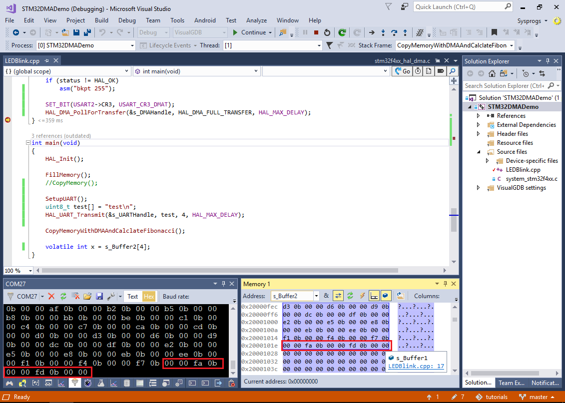
- Run the new code and verify that the data transferred to the COM port matches the contents of s_Buffer1:
- We can also replace the call to HAL_DMA_Start() that manually specifies the address of USART2->DR and the manual update of the USART2->CR3 register with a higher-level call to HAL_UART_Transmit_DMA() that will do the necessary setup automatically:
    __HAL_LINKDMA(&s_UARTHandle, hdmatx, s_DMAHandle);
    status = HAL_UART_Transmit_DMA(&s_UARTHandle, (uint8_t *)s_Buffer1, sizeof(s_Buffer1));
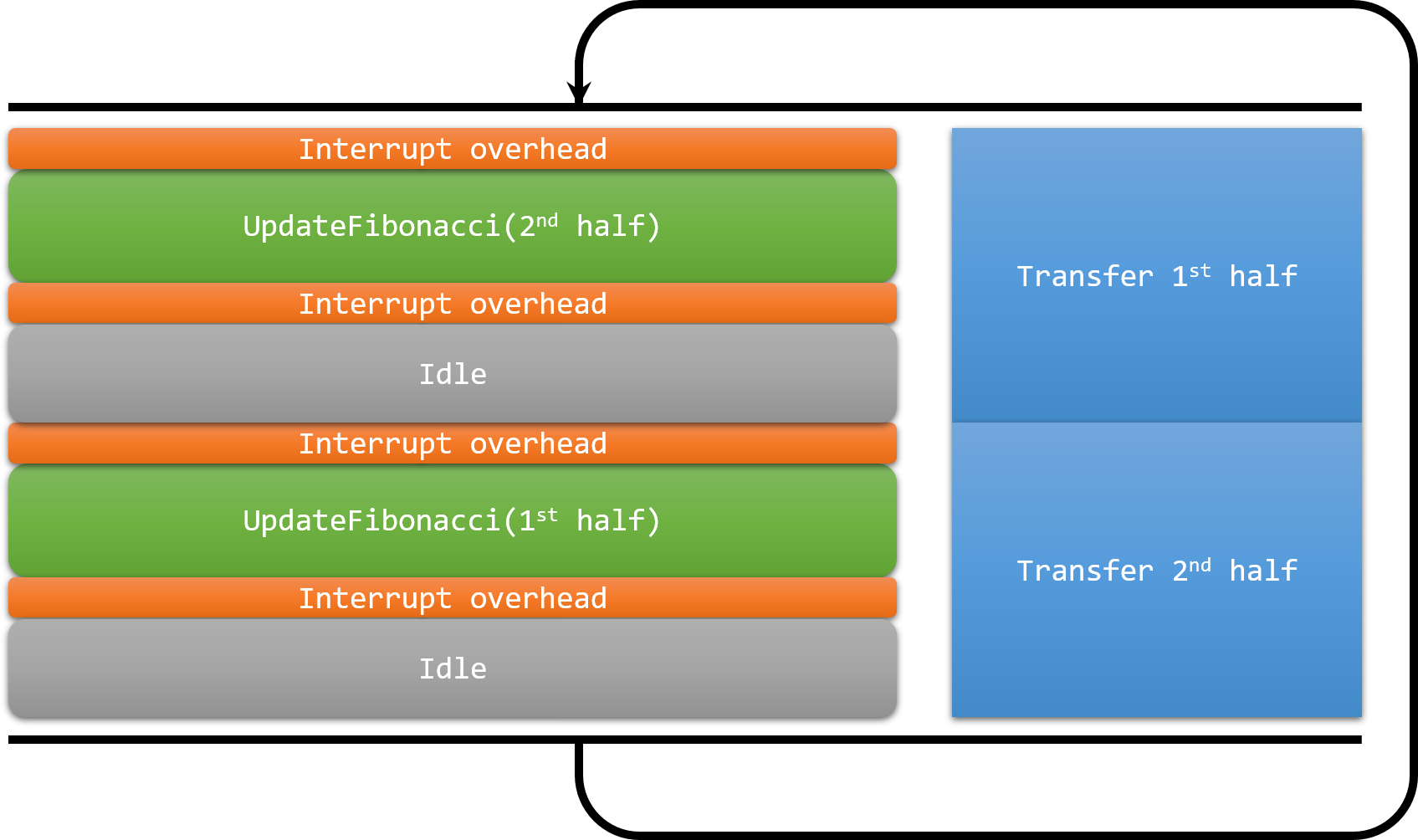
- Finally, we will show how to use the DMA in a scenario that is often impossible with CPU-driven data transfers – generating (or capturing) uninterrupted streams of data. We will update our example to continuously output the stream of Fibonacci numbers to UART without making any breaks by handling the DMA half-transfer interrupts. The DMA controller will be used to repeatedly transfer the same buffer to the UART peripheral over and over, while the CPU will be computing the next batch of values and placing them into the part of the buffer that has already been transferred:
- To do this, change the DMA mode assigned to s_DMAHandle.Init.Mode from DMA_NORMAL to DMA_CIRCULAR, enable the interrupt for the DMA channel you are using (in this example, by calling HAL_NVIC_EnableIRQ(DMA1_Stream6_IRQn)) and add the following handlers to your main source file:
extern "C" {
    void DMA1_Stream6_IRQHandler()
    {
        HAL_DMA_IRQHandler(&s_DMAHandle);
    }

    void HAL_UART_TxCpltCallback(UART_HandleTypeDef *huart)
    {
        asm("nop");
    }

    void HAL_UART_TxHalfCpltCallback(UART_HandleTypeDef *huart)
    {
        asm("nop");
    }
}
- Set a breakpoint in HAL_UART_TxHalfCpltCallback(), let it trigger and check the call stack:
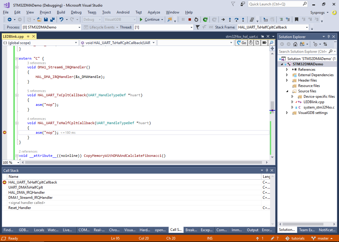 As the call stack shows, the DMA controller has raised an IRQ that invoked the DMA1_Stream6_IRQHandler() we created. In turn, our IRQ handler invoked the standard HAL_DMA_IRQHandler() function that sorted it out as a “Half of DMA buffer transferred” event, invoking the corresponding handler in the UART driver that finally called our HAL_UART_TxHalfCpltCallback() function.
 - We can now modify the HAL_UART_TxHalfCpltCallback() and HAL_UART_TxCpltCallback() to fill the second and first half of s_Buffer1 respectively with the next batch of Fibonacci numbers. First of all, add an UpdateFibonacci() function shown below:
void __attribute__((noinline)) UpdateFibonacci(int *pBuf, size_t count)
{
    static int s_Num1 = 0, s_Num2 = 1;

    int tmp1 = s_Num1, tmp2 = s_Num2;

    for (int i = 0; i < (count - 1); i+= 2)
    {
        pBuf[i] = tmp1;
        pBuf[i + 1] = tmp2;

        tmp1 += tmp2;
        tmp2 += tmp1;
    }

    s_Num1 = tmp1;
    s_Num2 = tmp2;
}
Then, update the UART callbacks as follows:
    void HAL_UART_TxCpltCallback(UART_HandleTypeDef *huart)
    {
        UpdateFibonacci(s_Buffer1, sizeof(s_Buffer1) / sizeof(s_Buffer1[0]) / 2);
    }

    void HAL_UART_TxHalfCpltCallback(UART_HandleTypeDef *huart)
    {
        const int ElementCount = sizeof(s_Buffer1) / sizeof(s_Buffer1[0]);
        UpdateFibonacci(s_Buffer1 + ElementCount / 2, ElementCount / 2);
    }
- Now you can run the final version of the project and observe an continuous stream of numbers being sent to the COM port: