Using the I2C Interface on the STM32 Devices
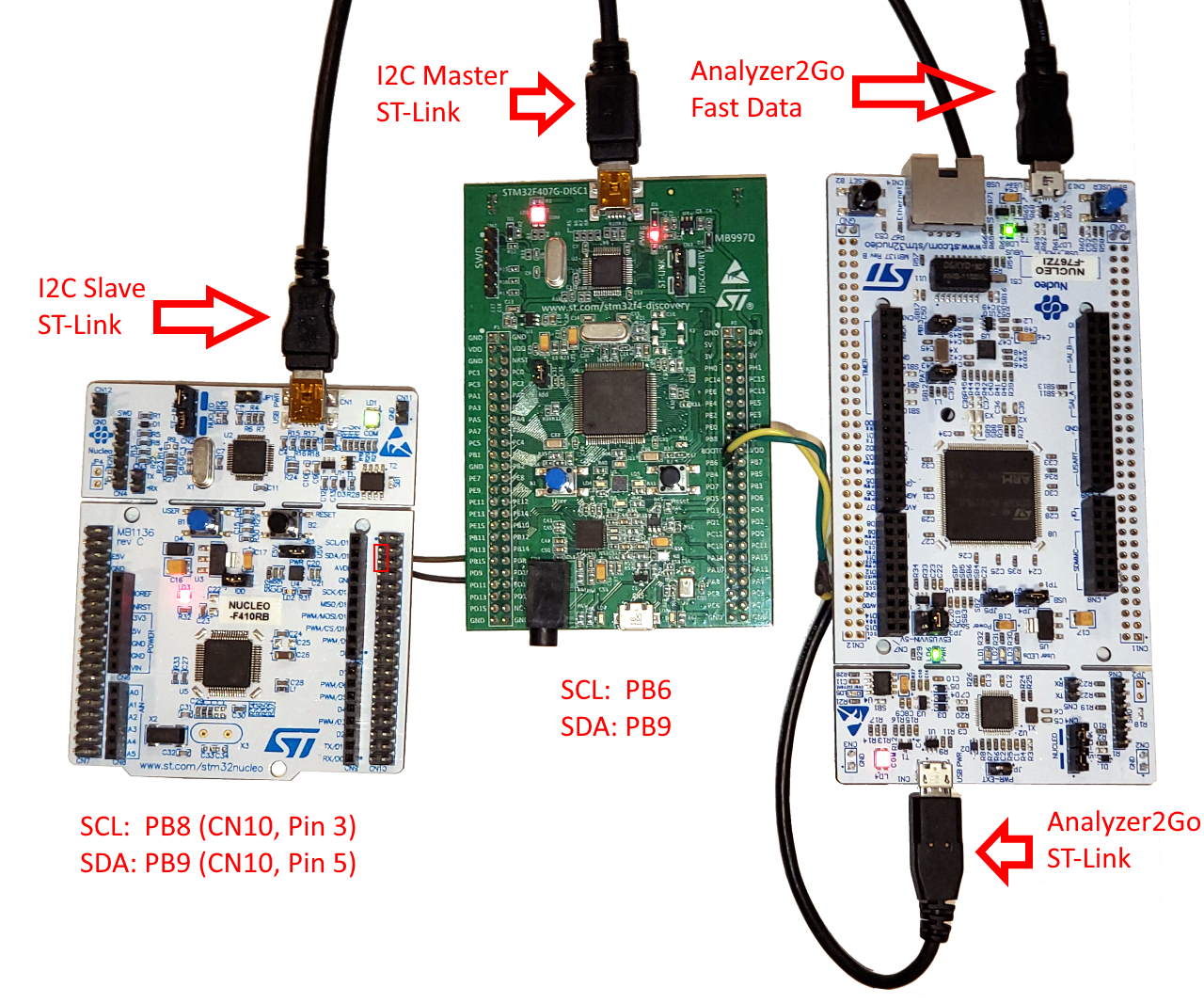
This tutorial shows how to use the I2C interface on the STM32 devices. We will connect 2 STM32 boards using their I2C interface, will go over the I2C packet format, and will show how to use the STM32 HAL API to send and receive message using I2C. We will use a third STM32 board together with Analyzer2Go to look into the I2C signals.
Before you begin, install Visual Studio and VisualGDB.
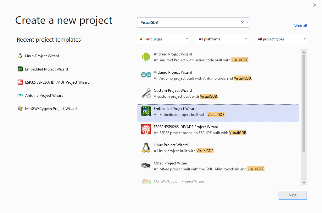
- We will begin with creating a basic project sending a simple message over I2C in the master mode. Start Visual Studio and open the VisualGDB Embedded Project Wizard:
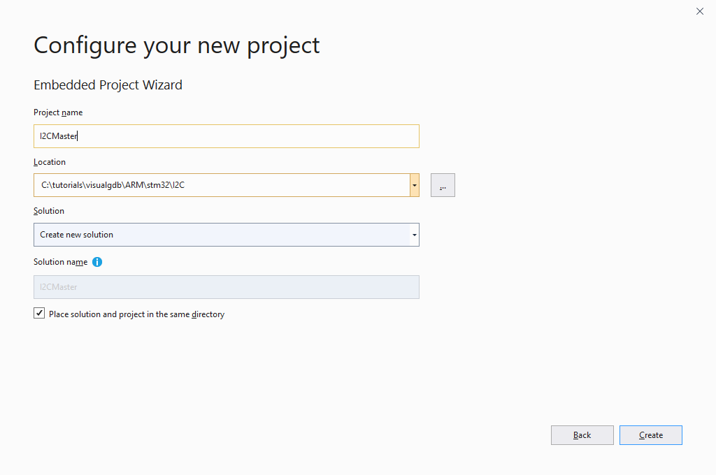
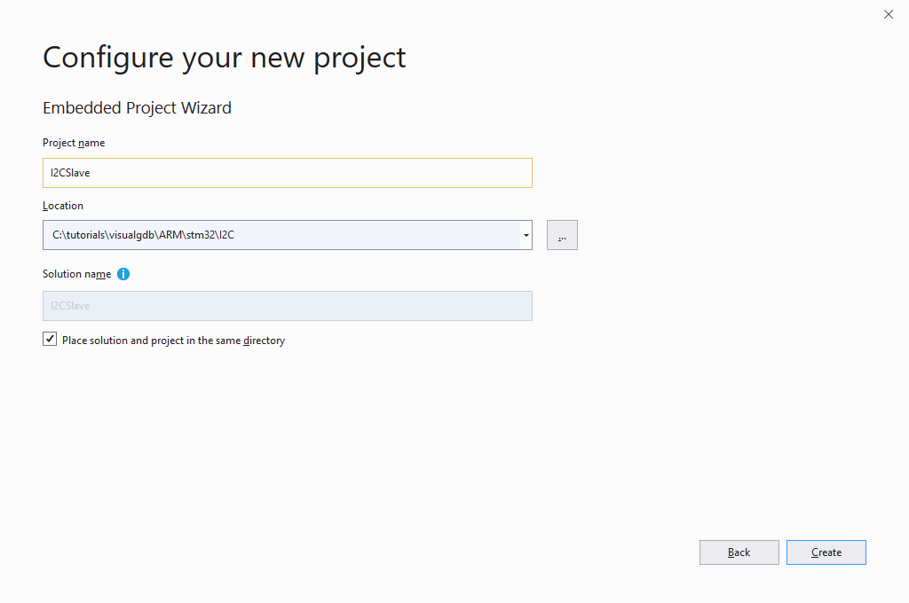
- Enter the name and location for your project and click “Create” to launch the VisualGDB-specific part of the wizard:
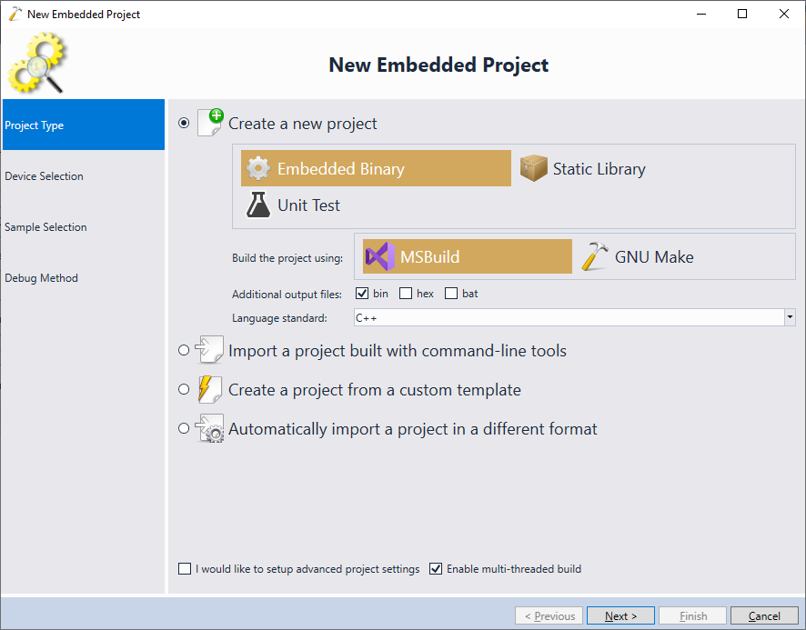
- Proceed with the default settings (Create a new Embedded Binary using MSBuild) on the first page of the VisualGDB’s Wizard:
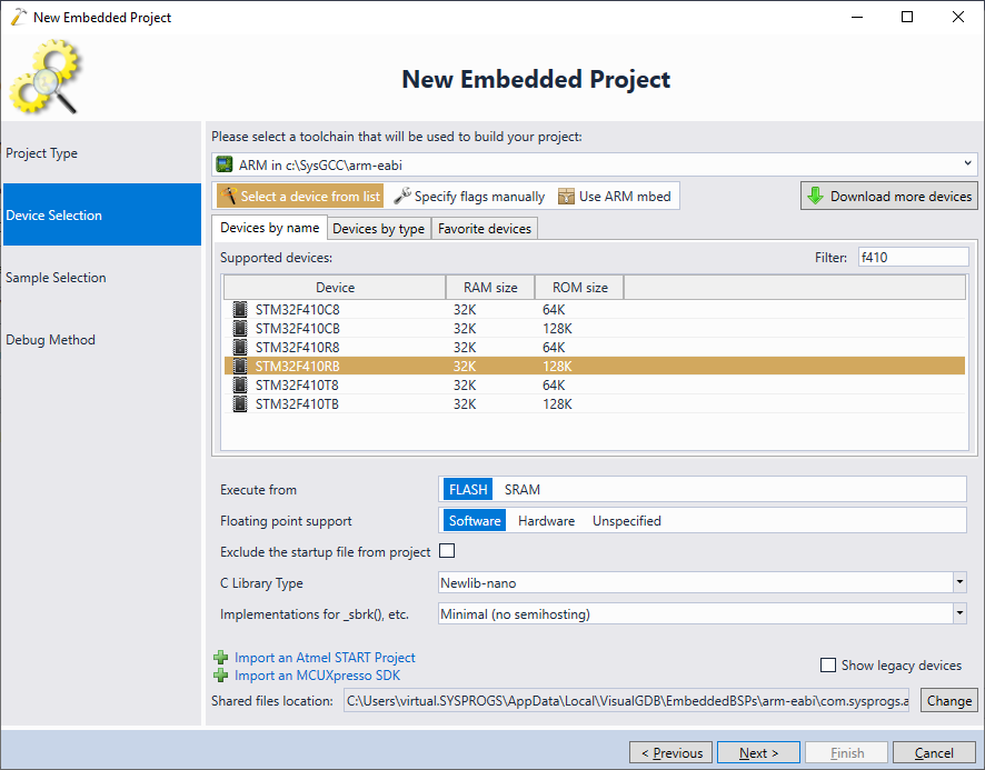
- On the next page, select your device. In this example, we will use the STM32F4-Discovery board for the I2C master, so we pick the STM32F407VG device:

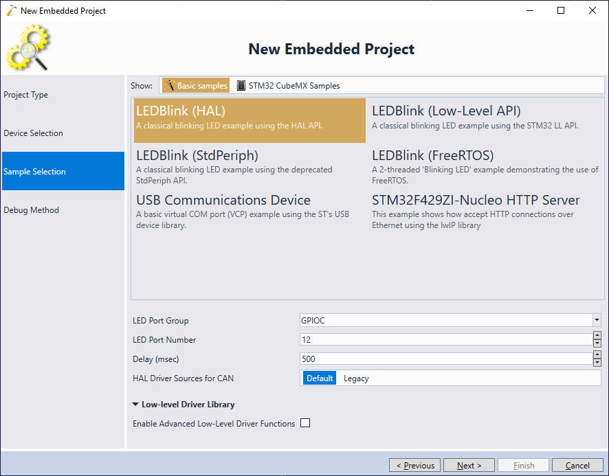
- Select the basic “LEDBlink” example on the next page. As we will be replacing the main() function with our own code, proceed with the default LED port settings even if they don’t match your board:
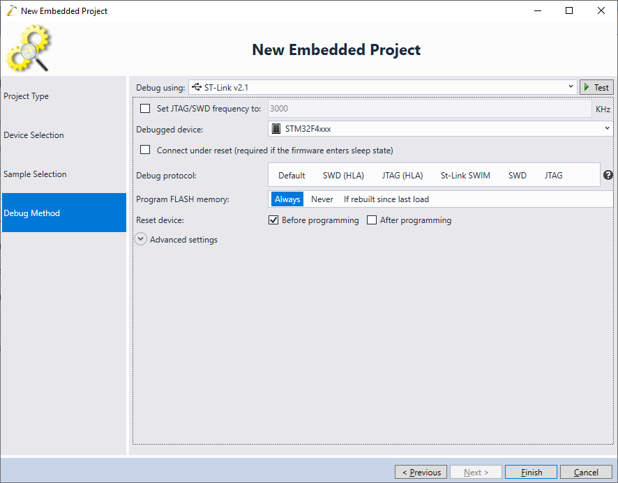
- Select debug settings that match your board and click “Finish” to create the project:
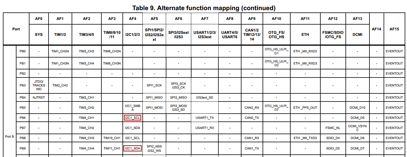
- The I2C protocol uses 2 physical signals: SCL (clock) and SDA (data). Open the datasheet (not reference manual) for your device and locate the pins that could be used for the I2C signals. In this example, we will use the pins PB6 and PB9 (both would need to be switched to the AF4 mode):
- Add the following function to your main file that will enable the GPIOB port and switch the PB6 and PB9 pins to the AF4 mode (I2C):
void ConfigureI2CPins()
{
    GPIO_InitTypeDef GPIO_InitStruct;

    GPIO_InitStruct.Pin = GPIO_PIN_6 | GPIO_PIN_9;
    GPIO_InitStruct.Mode = GPIO_MODE_AF_OD;
    GPIO_InitStruct.Pull = GPIO_PULLUP;
    GPIO_InitStruct.Speed = GPIO_SPEED_FAST;
    GPIO_InitStruct.Alternate = GPIO_AF4_I2C1;
    __GPIOB_CLK_ENABLE();
    HAL_GPIO_Init(GPIOB, &GPIO_InitStruct);
}
- Before we can start using the I2C peripheral from our code, we need to enable its clock by calling _I2C1_CLK_ENABLE() and configure it by calling HAL_I2C_Init(). To do this, replace the contents of your main() function with the following code:
    HAL_Init();
    ConfigureI2CPins();

    I2C_HandleTypeDef hI2C = I2C_HandleTypeDef();

    hI2C.Instance = I2C1;
    hI2C.Init.AddressingMode = I2C_ADDRESSINGMODE_7BIT;
    hI2C.Init.ClockSpeed = 10240;
    hI2C.Init.DutyCycle = I2C_DUTYCYCLE_2;

    __I2C1_CLK_ENABLE();

    if (HAL_I2C_Init(&hI2C) != HAL_OK)
        asm("bkpt 255");
The HAL_I2C_Init() function included in the STM32 SDK will automatically read the high-level parameters, such as AddressingMode, and will configure the I2C hardware accordingly. Below is an overview of the main I2C configuration parameters passed to HAL_I2C_Init(). Note that we have selected the 7-bit addressing mode, each I2C transmission will start with a byte consisting of a 7-bit address and 1 direction bit (specifying whether it’s a read or a write). We will explain this in detail later in the tutorial.
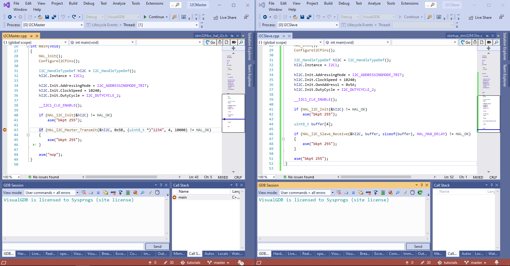
- Finally, add the following code to actually transmit some sample data over I2C and build the project via Build->Build Solution:
    if (HAL_I2C_Master_Transmit(&hI2C, 0x5A, (uint8_t *)"1234", 4, 10000) != HAL_OK)
    {
        asm("bkpt 255");
    }
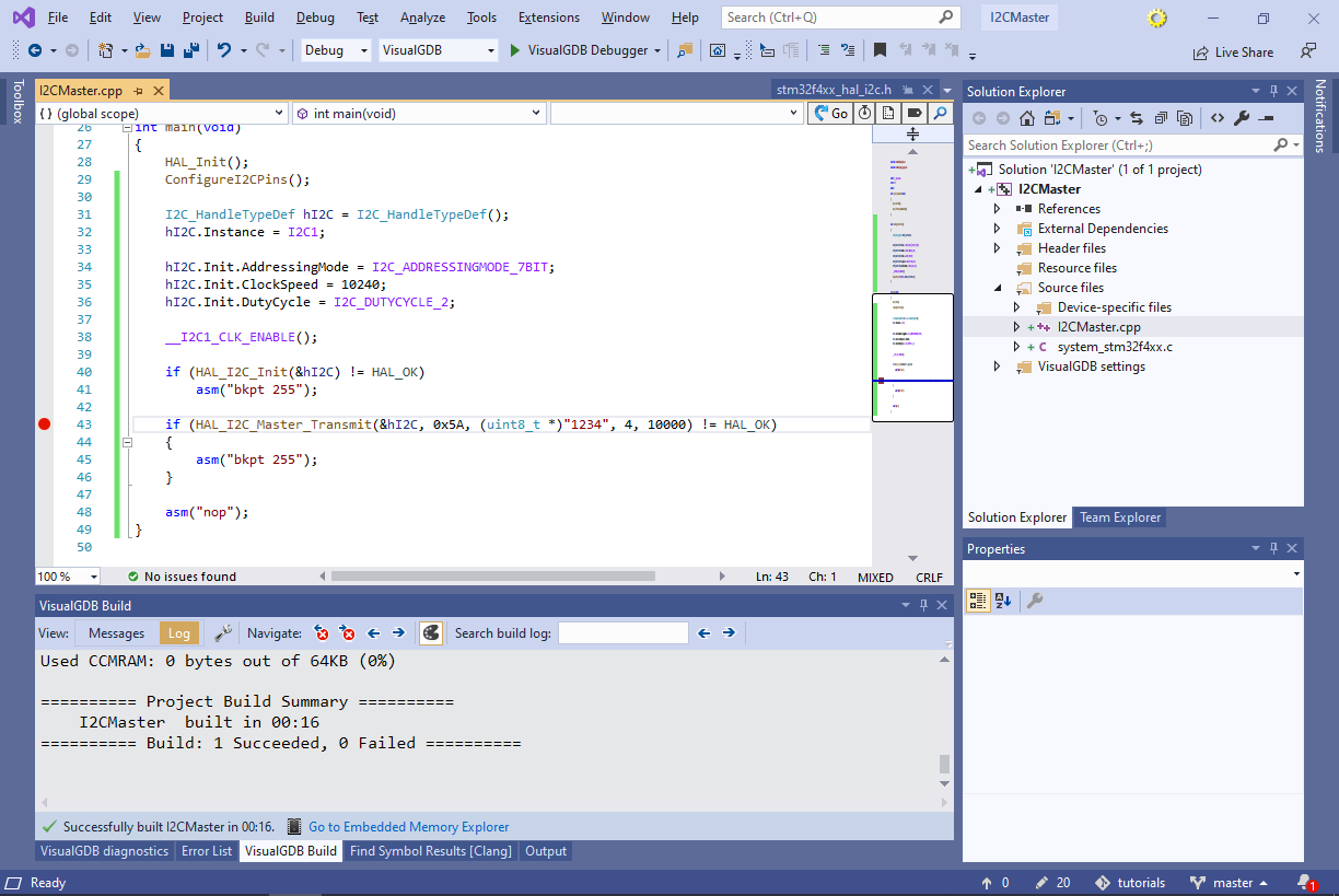
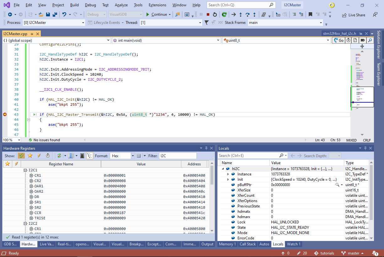
- Set a breakpoint on the HAL_I2C_Master_Transmit() call and press F5 to start debugging. Once the brekapoint triggers, the device will be ready to send the data via the I2C interface:
- Before we create an I2C slave firmware for the second board (that would accept transmissions from the I2C master), we will use a logic analyzer to have a detailed look into the I2C signals. In this tutorial, we will use Analyzer2Go to sample the I2C signals using a third STM32 board. Launch Analyzer2Go and select your the board you want to use as a logic analyzer from the list:

- Press OK to initialize the board. Analyzer2Go will show the ports that could be used a inputs. Connect the SCL and SDA signals (PB6 and PB9 in this tutorial) to the logic analyzer inputs and make sure that both USB ports of the logic analyzer boards are connected to your computer:

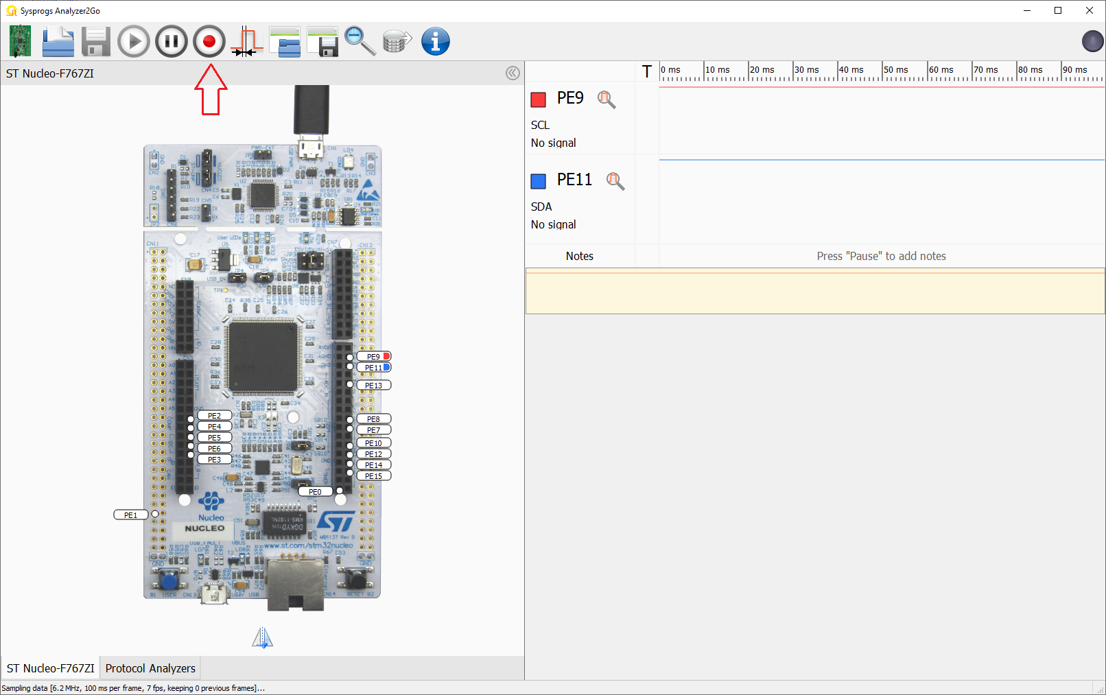
It is also recommended to connect the ground signals of both boards, even if they are connected to the same USB controller. - Enable the logic analyzer inputs that are connected to the I2C signals and name them (e.g. SCL and SDA). Then press the Record button to begin continuous recording:
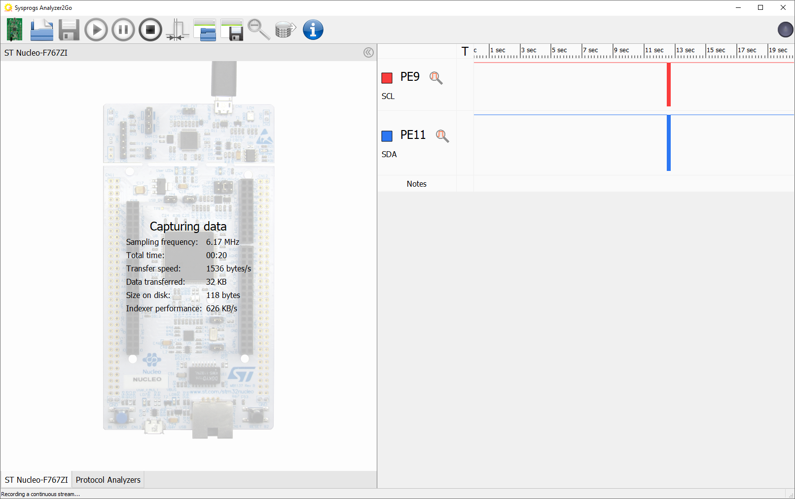
- Once Analyzer2Go is recording, step over the HAL_I2C_Master_Transmit() call. The call will return an error and Analyzer2Go will display some activity on the SCL and SDA pins:
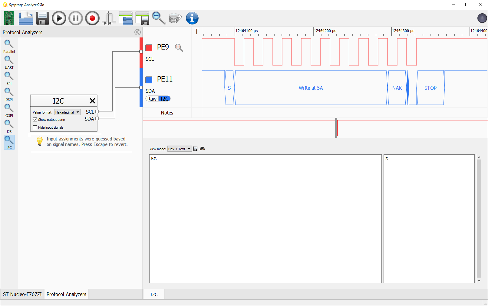
- Stop the recording, click on the magnifying lens symbol on the SCL signal to automatically zoom to a meaningful display, and switch to the Protocol Analyzers page in Analyzer2Go:

- Drag the I2C analyzer to the Protocol Analyzers area and connect its inputs. Analyzer2Go will decode the I2C transmission, showing how it consists of a START bit, a WRITE request at address of 0x5A followed by a NAK, that caused the HAL_I2C_Master_Transmit() call to fail:
- Switch the SDA view to raw to examine what exactly is going on with the SCL and SDA signals:
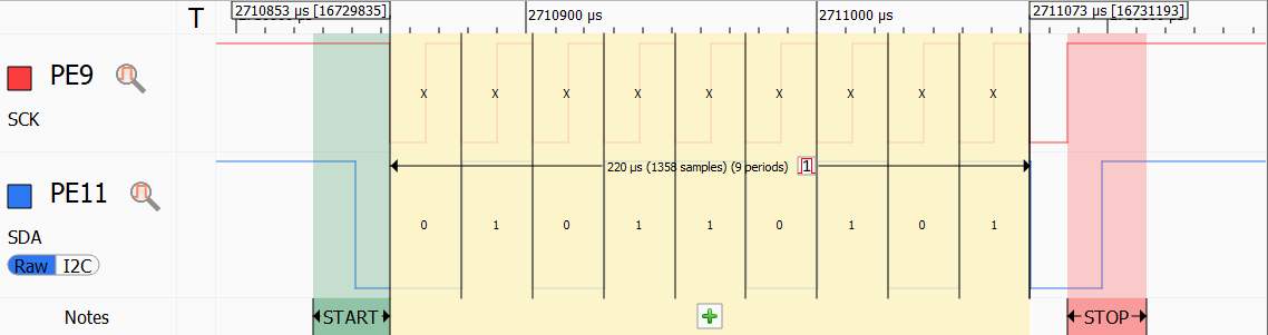
The I2C master begins the transmission by setting the SDA signal to 0, then transmits 7 address bits (0101101) followed by 0 indicating a write. Then it waits for the slave to acknowledge the transmission by holding the SDA at 0 after the direction bit. As there is no slave connected to the master yet, the SDA line remains high, indicating a NAK.
Note that the address passed to HAL_I2C_Master_Transmit() is aligned to the left per ST’s documentation. This means that the least significant bit of the 8-bit value passed to the function is always replaced by the direction bit. I.e. writing to address 0x5B (01011011) would be equivalent to writing to 0x5A (01011010). - Now we will connect the I2C slave board that will receive the data from the master board. Pick a board that has I2C pins exposed and make a note of their numbers and locations. In this tutorial, we will use the STM32F410-Nucleo board, that has the I2C signals on the PB6 and PB8 pins:
Signal STM32F4-Discovery STM32F410RB-Nucleo SCL PB6 PB8 (CN10, Pin 3) SDA PB9 PB9 (CN10, Pin 5) - Connect both boards used for I2C to the USB and make sure the SCL/SDA signals and ground are connected:
- Now we will create a project for the I2C Slave board. Open another Visual Studio instance and launch the VisualGDB Embedded Project Wizard again:
- Pick the device for your second board, and otherwise proceed with the same settings you used when creating the Master project:
- The basic I2C slave project has 3 differences from the I2C master project:
- Instead of using the PB6 pin for the SCL signal, it uses PB8 (per board layout)
- The initialization logic sets the hI2C.Init.OwnAddress1 to the address used by the master board
- Instead of calling HAL_I2C_Master_Transmit(), it calls HAL_I2C_Slave_Receive()
The final code for the STM32F410-Nucleo board looks as follows:
void ConfigureI2CPins()
{
    GPIO_InitTypeDef GPIO_InitStruct;
    GPIO_InitStruct.Pin = GPIO_PIN_8 | GPIO_PIN_9;
    GPIO_InitStruct.Mode = GPIO_MODE_AF_OD;
    GPIO_InitStruct.Pull = GPIO_PULLUP;
    GPIO_InitStruct.Speed = GPIO_SPEED_FAST;
    GPIO_InitStruct.Alternate = GPIO_AF4_I2C1;

    __GPIOB_CLK_ENABLE();

    HAL_GPIO_Init(GPIOB, &GPIO_InitStruct);
}

int main(void)
{
    HAL_Init();
    ConfigureI2CPins();

    I2C_HandleTypeDef hI2C = I2C_HandleTypeDef();
    hI2C.Instance = I2C1;
    hI2C.Init.AddressingMode = I2C_ADDRESSINGMODE_7BIT;
    hI2C.Init.ClockSpeed = 10240;
    hI2C.Init.OwnAddress1 = 0x5A;
    hI2C.Init.DutyCycle = I2C_DUTYCYCLE_2;

    __I2C1_CLK_ENABLE();

    if (HAL_I2C_Init(&hI2C) != HAL_OK)
        asm("bkpt 255");

    uint8_t buffer[4];
    if (HAL_I2C_Slave_Receive(&hI2C, buffer, sizeof(buffer), HAL_MAX_DELAY) != HAL_OK)
    {
        asm("bkpt 255");
    }

    asm("bkpt 255");
}
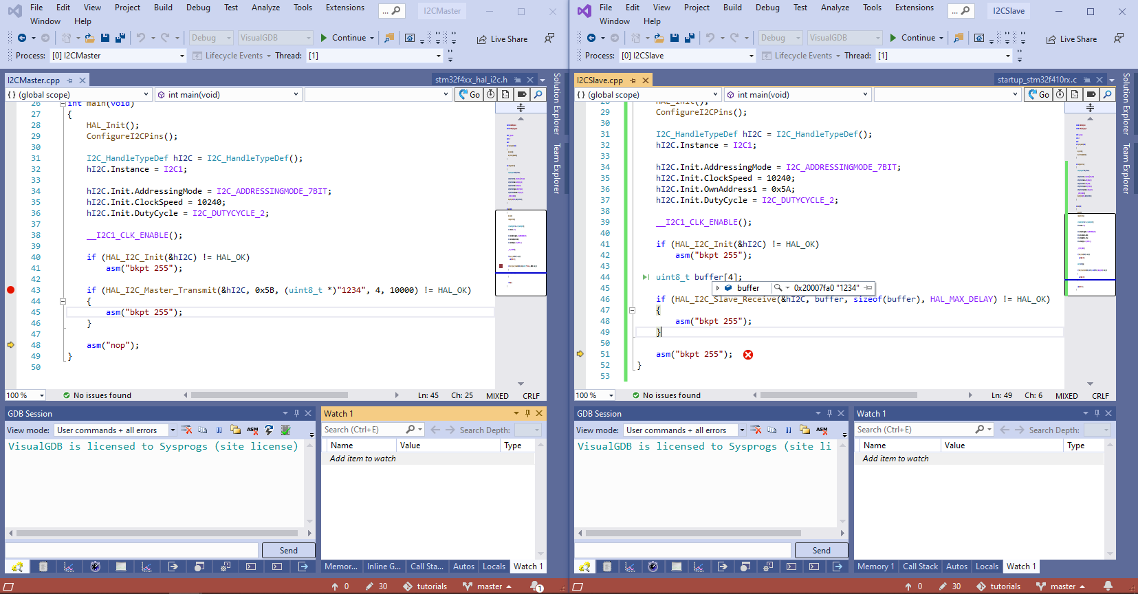
- Now we will try out the basic message transmission. First, launch the slave firmware and make sure it starts running the HAL_I2C_Slave_Receive() function, that will wait for the message. Then, start the master firmware and and get ready to step over HAL_I2C_Master_Transmit():
- As soon as you step over HAL_I2C_Master_Transmit(), the HAL_I2C_Slave_Receive() function on the slave board will return. The buffer variable will contain the message sent from the master:
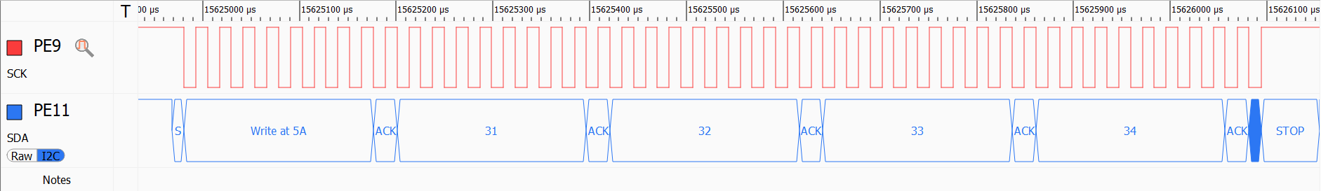
- If you were recording the transmission with Analyzer2Go, it will show a “Write at 5A” header followed by 4 bytes: 0x31, 0x32, 0x33 and ox34, corresponding to the “1234” message:
- Switch to the raw view to see what is going on at the lowest level:
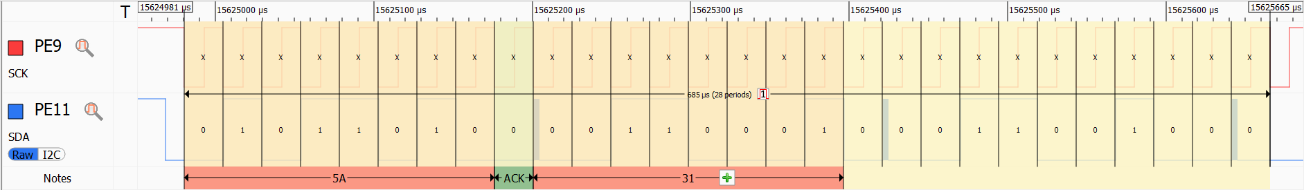 Each I2C transmission consists of a 9 bits (8-bit data packet followed by the ACK/NAK bit). The first packet always contains the 7-bit target address and the Read/Write bit. The subsequent packets contain raw 8-bit bytes, as sent by the firmware.
Note how before we connected the slave board, the first packet was not acknowledged (the SDA pin was high during the ACK/NAK phase) and the master immediately aborted the rest of the transmission. Now that the slave is present (and acknowledged the address packet), the master continued sending out the actual payload. - Now we will play around with various I2C parameters and will show how it affects the physical data transmitted via the I2C pins. First of all, we will change the transfer direction, sending the data from the slave to the master:
    //Master
    uint8_t buffer[4];
    if (HAL_I2C_Master_Receive(&hI2C, 0x5A, buffer, sizeof(buffer), 10000) != HAL_OK)
    {
        asm("bkpt 255");
    }
    //Slave
    if (HAL_I2C_Slave_Transmit(&hI2C, (uint8_t *)"5678", 4, HAL_MAX_DELAY) != HAL_OK)
    {
        asm("bkpt 255");
    }
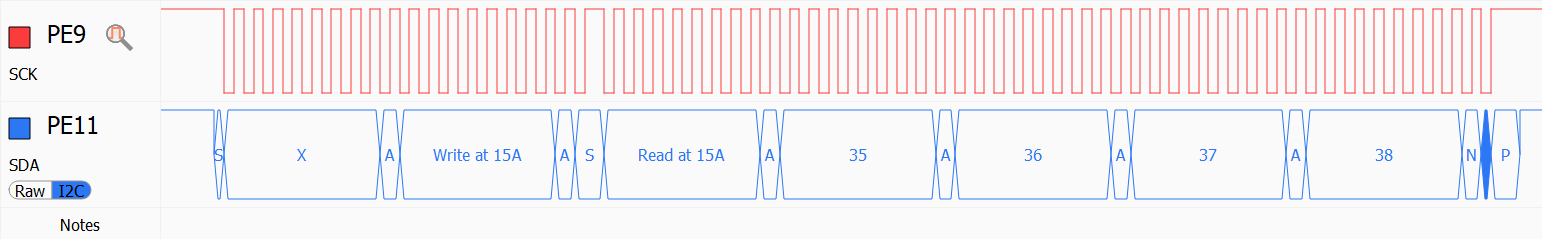
- The first packet will change from “Write at 5A” (raw value of 01011010) to “Read at 5A” (raw value of 01011011) and the SDA pin will be driven by the slave board during the payload transfers:

- The following table summarizes the physical data transferred via the I2C bus during the 2 sample transfers:
Write “1234” to 0x5A Read “5678” from 0x5A Byte #0 0x5A (left-aligned address, LSB = 0) 0x5B (left-aligned adderss, LSB = 1) Byte #1 0x31 (‘1’) 0x35 (‘5’) Byte #2 0x32 (‘2’) 0x36 (‘6’) Byte #3 0x33 (‘3’) 0x37 (‘7’) Byte #4 0x34 (‘4’) 0x38 (‘8’) - Now we will show how to use 10-bit addresses instead of 7-bit ones. Replace the I2C_ADDRESSINGMODE_7BIT value with I2C_ADDRESSINGMODE_10BIT in both master and slave firmware. Then change address from 0x5A to 0x15A. Observe how the I2C communication changes:
 In order to maintain compatibility to the 7-bit devices, each 10-bit transfer always starts as if it was a write to a special address (1111 0XX0). The two X bits store the 2 most-significant bits of the 10-bit address. The next byte contains the remaining 8 bits of the 10-bit address (7-bit devices will treat it as a regular data byte sent to some other device). For write transactions, the payload immediately follows the address byte. For read transactions, the master generates a START condition (without a STOP one) after sending the address byte, and then initiates a read from the special address (1111 0XX1). Below is a byte-level breakdown of the sample transfers using 10-bit addressing:
Write “1234” to 0x15A Read “5678” from 0x15A Byte #0 0xF2 (1111 0010). Transmits the 2 most significant bits of the address (01 = 0x1). Byte #1 0x5A Between bytes #1 and #2 Nothing START condition Byte #2 0x31 (‘1’) 0xF3 (1111 0011). Starts a READ sequence. Byte #3 0x32 (‘2’) 0x35 (‘5’) Byte #4 0x33 (‘3’) 0x36 (‘6’ Byte #5 0x34 (‘4’) 0x37 (‘7’) Byte #6 0x38 (‘8’) - Now we will show how to move the I2C-related logic into the background by using the interrupt-driven and DMA-driven I2C API. Before we do that, modify the slave I2C firmware to continuously receive and acknowledge 4096-byte chunks of data:
    uint8_t buffer[4096];
    for (;;)
    {
        HAL_I2C_Slave_Receive(&hI2C, buffer, sizeof(buffer), HAL_MAX_DELAY);
    }
We will keep the slave firmware unchanged for the rest of the tutorial and will demonstrate different transfer modes by changing the master firmware.
- First of all, we will demonstrate the interrupt-driven mode. Unlike the regular HAL_I2C_Master_Transmit() function, that does not return until the entire transfer is complete, the interrupt-driven mode (HAL_I2C_Master_Transmit_IT()) returns almost immediately and lets the main program continue, while the I2C transfer is in progress. After each transferred byte, the hardware will raise an I2C interrupt, requesting the HAL drivers to send the next byte or call the end-of-transfer callback. In order to convert the current master firmware to the interrupt mode, move the hI2C variable to the global scope and add the following functions:
I2C_HandleTypeDef hI2C;
extern "C" void I2C1_EV_IRQHandler()
{
    HAL_I2C_EV_IRQHandler(&hI2C);
}

extern "C" void HAL_I2C_MasterTxCpltCallback(I2C_HandleTypeDef *hi2c)
{
    asm("bkpt 255");
}
The I2C1_EV_IRQHandler() will immediately call the HAL_I2C_EV_IRQHandler() function included in the STM32 HAL, that will determine the cause of the interrupt, and handle it accordingly. When the entire transfer is complete, it will call the HAL_I2C_MasterTxCpltCallback() function.
- Update the main() function in the master firmware as shown below:
    if (HAL_I2C_Init(&hI2C) != HAL_OK)
        asm("bkpt 255");

    uint8_t tempBuffer[4096];
    for (int i = 0; i < sizeof(tempBuffer); i++)
        tempBuffer[i] = i;

    NVIC_EnableIRQ(I2C1_EV_IRQn);

    if (HAL_I2C_Master_Transmit_IT(&hI2C, 0x15B, tempBuffer, sizeof(tempBuffer)) != HAL_OK)
    {
        asm("bkpt 255");
    }

    for (;;)
    {
        asm("nop");
    }
- Set a breakpoint at the call to HAL_I2C_Master_Transmit_IT() and wait for it to trigger. Then launch the slave firmware so that it begins listening on the I2C interface. Finally, resume the master. The breakpoint in HAL_I2C_MasterTxCpltCallback() will trigger:
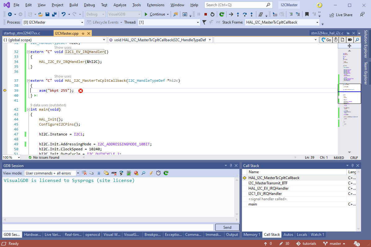 The call stack will show how the main() function was interrupted by the I2C interrupt, that invoked HAL_I2C_EV_IRQHandler() function, that, in turn, called HAL_I2C_MasterTxCpltCallback().
 - We can visualize the interrupt handler timing by setting an arbitrary GPIO pin from it and observing it via Analyzer2Go. Add the following code to Configure I2CPins():
    __GPIOC_CLK_ENABLE();
    GPIO_InitStruct.Pin = GPIO_PIN_10 | GPIO_PIN_11 | GPIO_PIN_12;
    GPIO_InitStruct.Mode = GPIO_MODE_OUTPUT_PP;
    HAL_GPIO_Init(GPIOC, &GPIO_InitStruct);
Then update the I2C interrupt handler to raise and lower the GPIOC12 pin before/after calling HAL_I2C_EV_IRQHandler():
extern "C" void I2C1_EV_IRQHandler()
{
    HAL_GPIO_WritePin(GPIOC, GPIO_PIN_12, GPIO_PIN_SET);
    HAL_I2C_EV_IRQHandler(&hI2C);
    HAL_GPIO_WritePin(GPIOC, GPIO_PIN_12, GPIO_PIN_RESET);
}
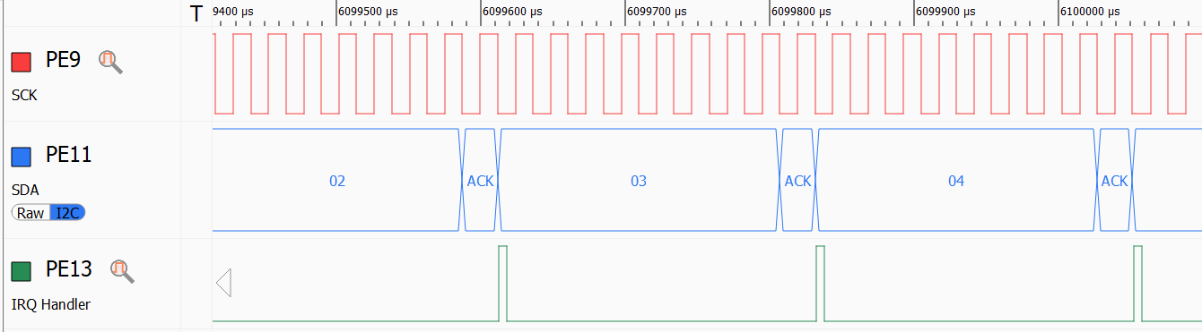
Observe how the pin controlled from I2C1_EV_IRQHandler() goes high for a short period of time after each payload byte is acknowledged, and then quickly goes low again, indicating that the control has returned to the main() function:
- Finally, we will show how to transfer the data via the I2C interface using the DMA controller. Unlike the interrupt-driven mode where the hardware raises an interrupt after each byte, DMA mode can handle the entire memory buffer without interrupting the main firmware. Each peripheral (such as I2C) is associated with a specific stream/channel of the DMA controller. You can find the specifics for your device by searching for “DMA1 Request Mapping” in the ST reference manual:
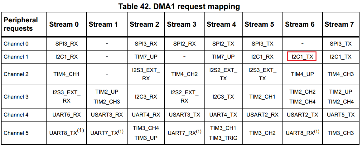 For STM32F407, the outgoing I1C1 transfers are done using Stream 6 of Channel 1 on DMA1.
 - In order to use transfer data via I2C using DMA, first declare an instance of the DMA handle:
static DMA_HandleTypeDef s_DMAHandle = DMA_HandleTypeDef();
Then, add the following logic to main():
    __DMA1_CLK_ENABLE();
    s_DMAHandle.Instance = DMA1_Stream6;
    s_DMAHandle.Init.Channel = DMA_CHANNEL_1;

    s_DMAHandle.Init.Direction = DMA_MEMORY_TO_PERIPH;
    s_DMAHandle.Init.PeriphInc = DMA_PINC_DISABLE;
    s_DMAHandle.Init.MemInc = DMA_MINC_ENABLE;
    s_DMAHandle.Init.Mode = DMA_NORMAL;

    s_DMAHandle.Init.Priority = DMA_PRIORITY_VERY_HIGH;

    s_DMAHandle.Init.PeriphDataAlignment = DMA_PDATAALIGN_BYTE;
    s_DMAHandle.Init.MemDataAlignment = DMA_PDATAALIGN_BYTE;

    if (HAL_DMA_Init(&s_DMAHandle) != HAL_OK)
        asm("bkpt 255");

    __HAL_LINKDMA(&hI2C, hdmatx, s_DMAHandle);
    NVIC_EnableIRQ(DMA1_Stream6_IRQn);
    NVIC_EnableIRQ(I2C1_EV_IRQn);
Replace the call to HAL_I2C_Master_Transmit_IT() with HAL_I2C_Master_Transmit_DMA():
    if (HAL_I2C_Master_Transmit_DMA(&hI2C, 0x15B, tempBuffer, sizeof(tempBuffer)) != HAL_OK)
    {
        asm("bkpt 255");
    }
Finally, add an interrupt handler for the related DMA channel (keep the existing I2C interrupt handler as well):
extern "C" void I2C1_EV_IRQHandler()
{
    HAL_GPIO_WritePin(GPIOC, GPIO_PIN_10, GPIO_PIN_SET);
    HAL_I2C_EV_IRQHandler(&hI2C);
    HAL_GPIO_WritePin(GPIOC, GPIO_PIN_10, GPIO_PIN_RESET);
}

extern "C" void DMA1_Stream6_IRQHandler()
{
    HAL_GPIO_WritePin(GPIOC, GPIO_PIN_12, GPIO_PIN_SET);
    HAL_DMA_IRQHandler(&s_DMAHandle);
    HAL_GPIO_WritePin(GPIOC, GPIO_PIN_12, GPIO_PIN_RESET);
}
- Now the entire block will get transferred at once, with minimal interrupts from I2C and DMA:
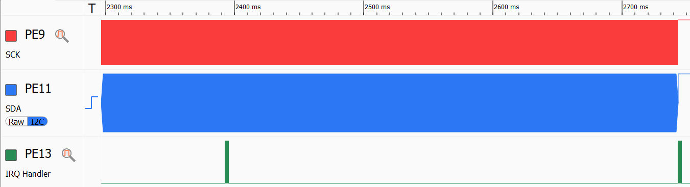 The hardware will still raise interrupts during the initial setup, and when one half of the DMA buffer is processed, but it will no longer interrupt the main program after each transferred byte.