Using the SPI interface on STM32 devices
This tutorial shows how to use the SPI interface of the STM32 devices using the STM32CubeMX HAL API. We will configure the SPI in several different modes, show how they affect the generated signal and setup the double-buffered mode to demonstrate continuous uninterrupted mode.
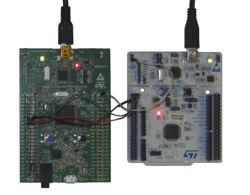
We will use an STM32F4Discovery board to demonstrate the SPI and a Nucleo-F411RE board with Analyzer2Go to capture and analyze the generated SPI signals.
Before you begin, install Visual Studio and VisualGDB:
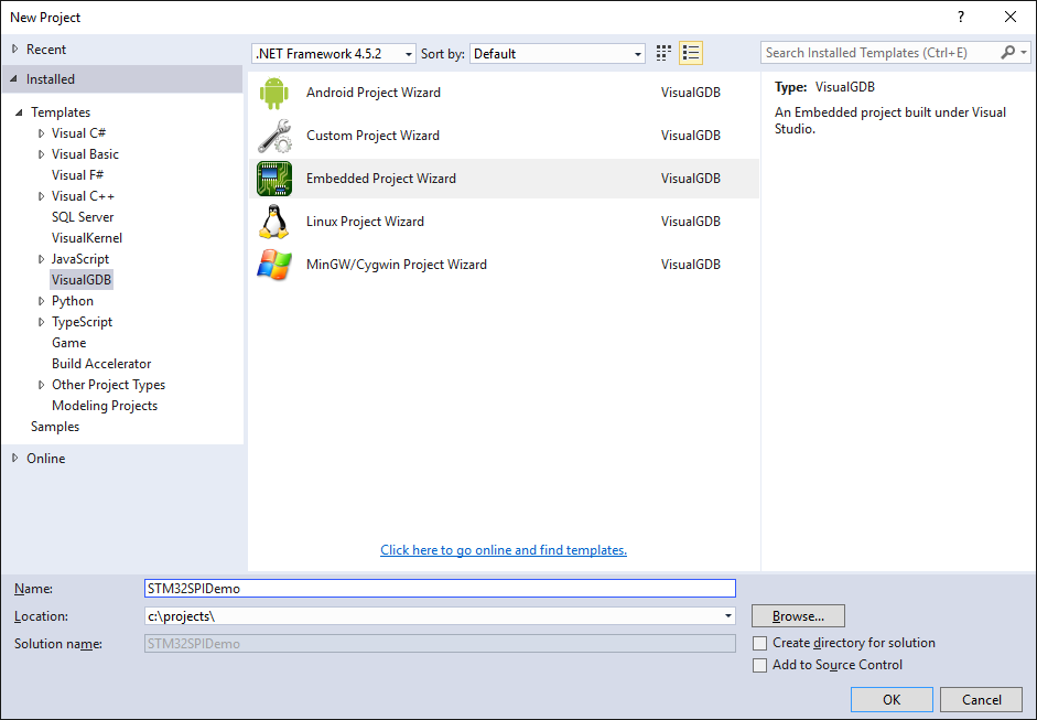
- Start Visual Studio and open the VisualGDB Embedded Project Wizard:
- Proceed with the default settings on the first page:

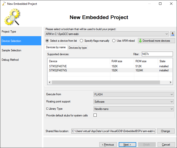
- On the next page select your STM32 device. In this tutorial we will use the STM32F4Discovery board that uses the STM32F407VG chip, however the techniques described here will work for other chips as well:
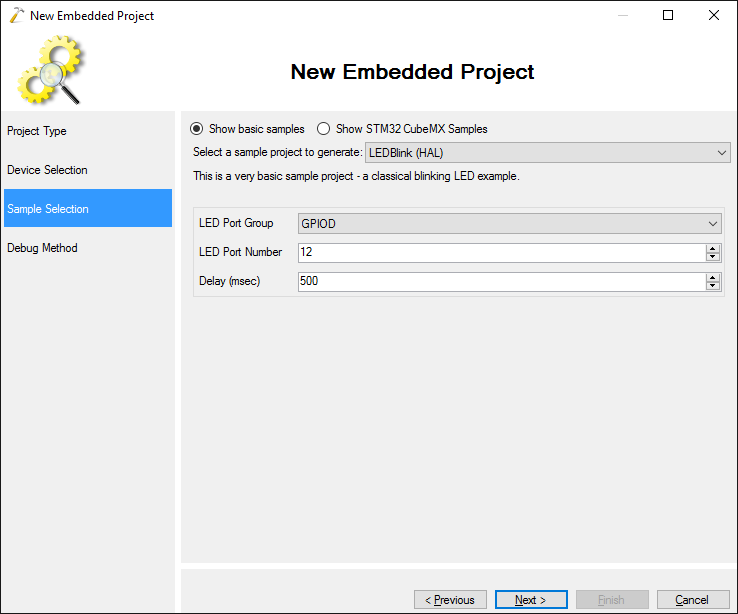
- Select the default “LEDBlink” example and click “Next”:
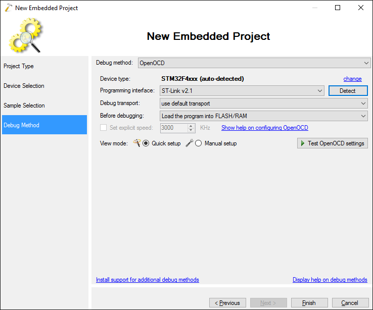
- Finally specify your debugging settings. For most STM32 devices programmable via ST-Link we recommend using OpenOCD. Connect your board to the computer and click ‘Detect’ to automatically detect your ST-Link interface:
- Click “Finish” to generate the basic project and ensure it builds. Now we will modify the project to send a basic message over the STM32 SPI interface. First of all, locate the datasheet for your STM32 device and find the pins that can be used for SPI. For STM32F407VG we will use pins PA4-PA7 with SPI1 (note tha alternate function number that is AF5 in this case):

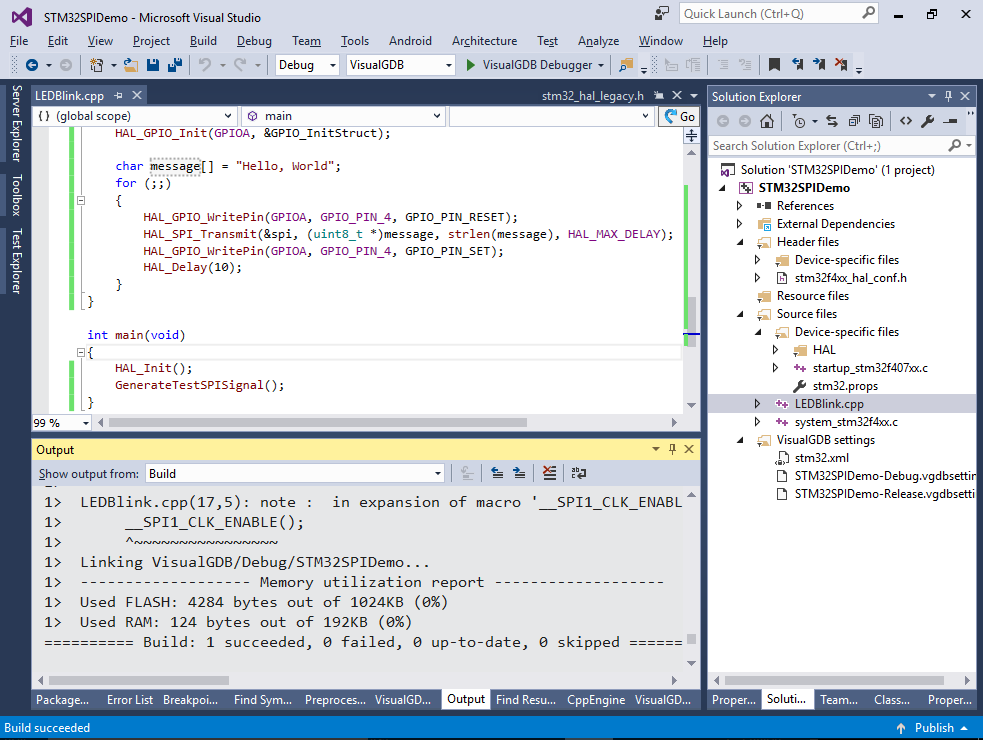
- Replace the contents of the main .cpp file with the following code:
#include <stm32f4xx_hal.h>

#ifdef __cplusplus
extern "C"
#endif
void SysTick_Handler(void)
{
    HAL_IncTick();
    HAL_SYSTICK_IRQHandler();
}

#include <string.h>

void GenerateTestSPISignal()
{

}

int main(void)
{
    HAL_Init();
    GenerateTestSPISignal();
}
- Add the code that will initialize the SPI peripheral to the GenerateTestSPISignal() function:
    __SPI1_CLK_ENABLE();
    static SPI_HandleTypeDef spi = { .Instance = SPI1 };
    spi.Init.BaudRatePrescaler = SPI_BAUDRATEPRESCALER_256;
    spi.Init.Direction = SPI_DIRECTION_2LINES;
    spi.Init.CLKPhase = SPI_PHASE_2EDGE;
    spi.Init.CLKPolarity = SPI_POLARITY_HIGH;
    spi.Init.CRCCalculation = SPI_CRCCALCULATION_DISABLED;
    spi.Init.DataSize = SPI_DATASIZE_8BIT;
    spi.Init.FirstBit = SPI_FIRSTBIT_LSB;
    spi.Init.NSS = SPI_NSS_SOFT;
    spi.Init.TIMode = SPI_TIMODE_DISABLED;
    spi.Init.Mode = SPI_MODE_MASTER;
    if (HAL_SPI_Init(&spi) != HAL_OK)
    {
        asm("bkpt 255");
    }
- If we begin using the SPI peripheral right after calling HAL_SPI_Init(), the peripheral will appear working from the program’s point of view, but the SPI signals will not be actually be visible on the chip pins. To fix this, we need to explicitly switch pins PA5-PA7 to the SPI mode. We will leave the PA4 pin to be a generic GPIO pin to demonstrate how to control the NSS signal manually:
    __GPIOA_CLK_ENABLE();
    GPIO_InitTypeDef  GPIO_InitStruct;

    GPIO_InitStruct.Pin       = GPIO_PIN_5 | GPIO_PIN_6 | GPIO_PIN_7;
    GPIO_InitStruct.Mode      = GPIO_MODE_AF_PP;
    GPIO_InitStruct.Pull      = GPIO_PULLUP;
    GPIO_InitStruct.Speed     = GPIO_SPEED_HIGH;
    GPIO_InitStruct.Alternate = GPIO_AF5_SPI1;

    HAL_GPIO_Init(GPIOA, &GPIO_InitStruct);

    GPIO_InitStruct.Pin  = GPIO_PIN_4;
    GPIO_InitStruct.Mode = GPIO_MODE_OUTPUT_PP;
    HAL_GPIO_Init(GPIOA, &GPIO_InitStruct);
Note that the GPIO_AF5_SPI1 corresponds to the alternate function number (AF5) for SPI1 from the Alternate Function table in the datasheet.
- Finally add the following code that will repeatedly transmit the “Hello, World” string over the SPI:
    char message[] = "Hello, World";
    for (;;)
    {
        HAL_GPIO_WritePin(GPIOA, GPIO_PIN_4, GPIO_PIN_RESET);
        HAL_SPI_Transmit(&spi, (uint8_t *)message, strlen(message), HAL_MAX_DELAY);
        HAL_GPIO_WritePin(GPIOA, GPIO_PIN_4, GPIO_PIN_SET);
        HAL_Delay(10);
    }
Note that we manually control the NSS signal by setting the PA4 pin value to 0 before the transmission and setting it back 1 after the transmission.
- Build the project and ensure that is succeeds without any errors:
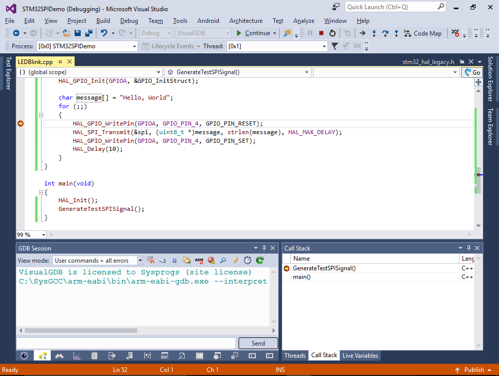
- Set a breakpoint on the first call to HAL_GPIO_WritePin() and start debugging. Ensure that the breakpoint hits:
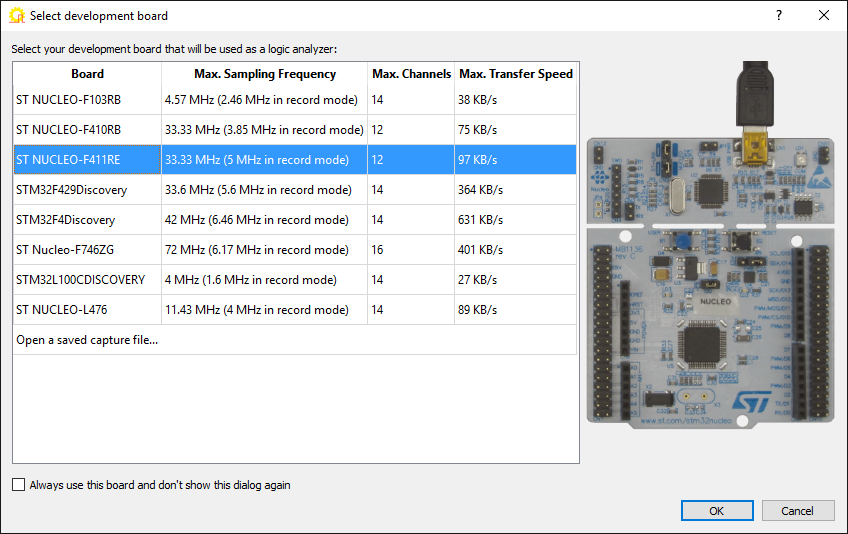
- Now we will use a logic analyzer to observe the SPI signals produced by the board. In this tutorial will use Analyzer2Go and the ST NUCLEO-F411RE board to capture and analyze the signals. If you don’t have the Nucleo-F411RE board, you can use any of the other boards supported by Analyzer2Go or an external logic analyzer. First start Analyzer2Go, connect the board you want to use as a logic analyzer and select it in the list:
- Then connect the relevant SPI signals (MOSI, SCLK and NSS) to the inputs of the logic analyzer board that are shown in the Analyzer2Go window. Do not forget to connect the ground between the 2 boards:
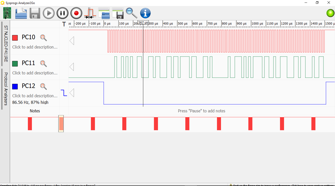
- Finally click on the connected signals in the Analyzer2Go window to immediately see the live SPI signal:
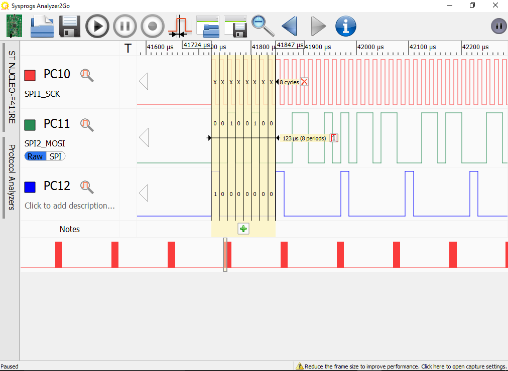
 Observe the repeated pattern: the NSS signal goes from 1 to 0 (indicating the start of a transmission), then the SCK and MOSI signals quickly change the values and the NSS gets back to 1.
 - Click in the “Trigger” column of the NSS signal so that the data frame gets aligned to the falling edge (start of transmission). Then double-click on any of the solid blocks in the SCK or MOSI signals to zoom in to see the actual signal:
 Observe the typical SPI signal waveform: the SCK clock generates monotonous clock pulses during the transmission and the MOSI signal (Master Output Slave Input) transmits the data one bit at a time.
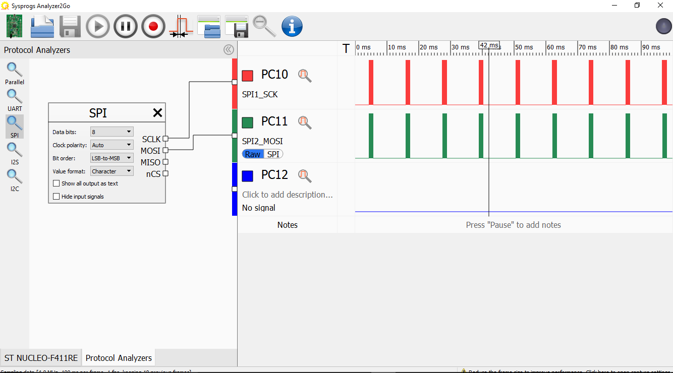
 - Add labels to the SCK and MOSI signals by clicking on “Click to add description”, then open the Protocol Analyzers tab, add and connect the SPI protocol analyzer:
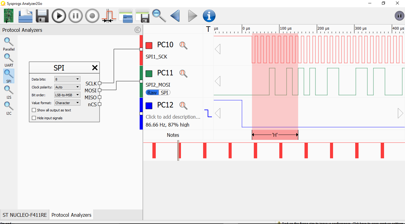
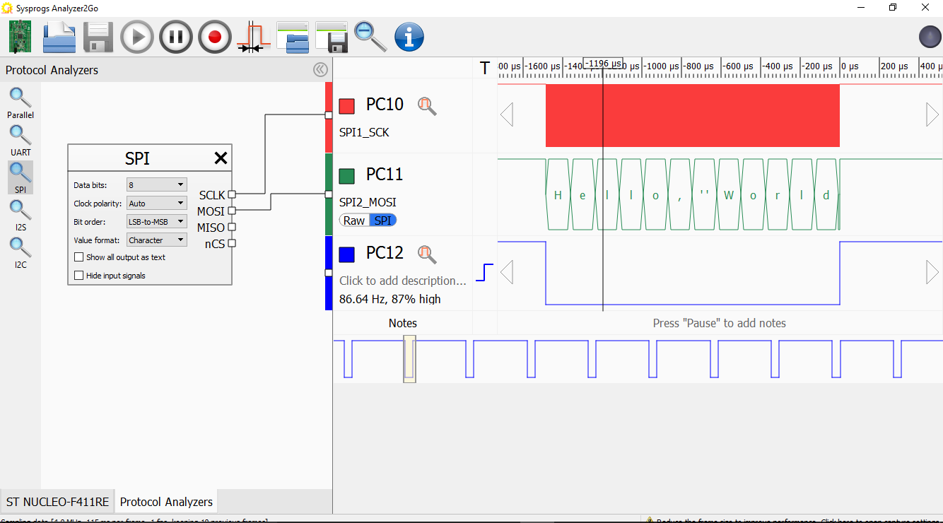
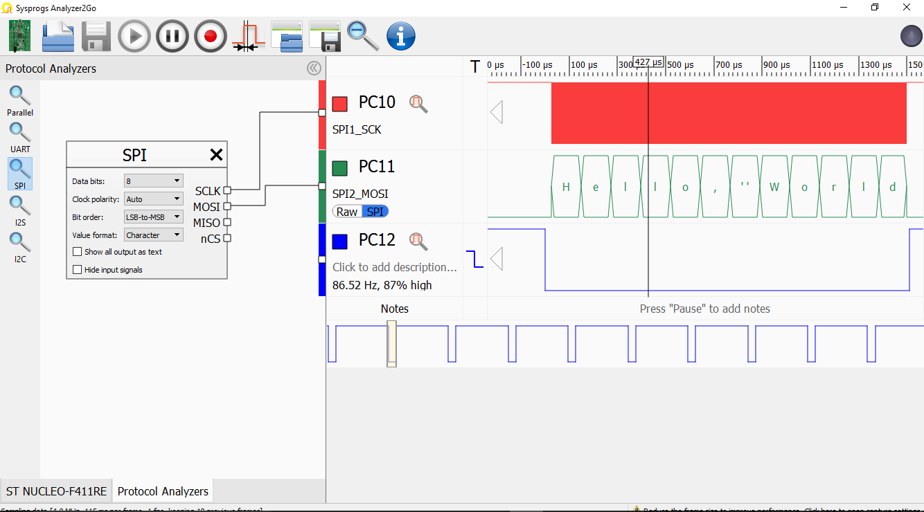 Observe how the “Hello, World” message got decoded.
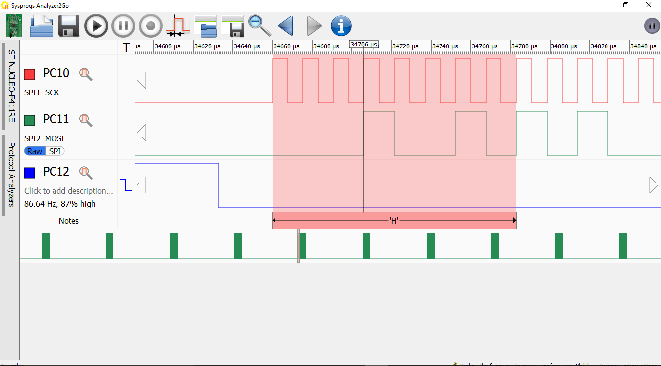
 - Now we will look how exactly the message is coded when using different SPI modes. Select the ‘H’ character and click on the Notes bar to add a note:
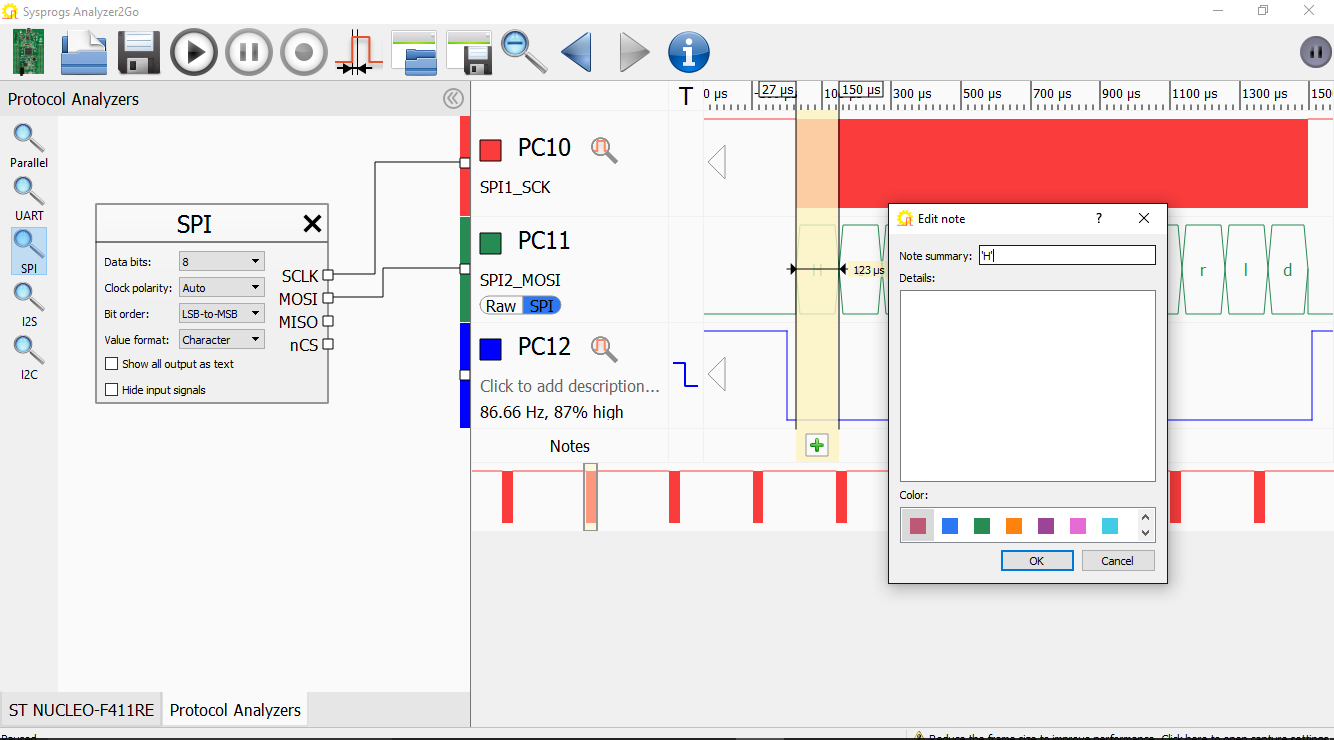
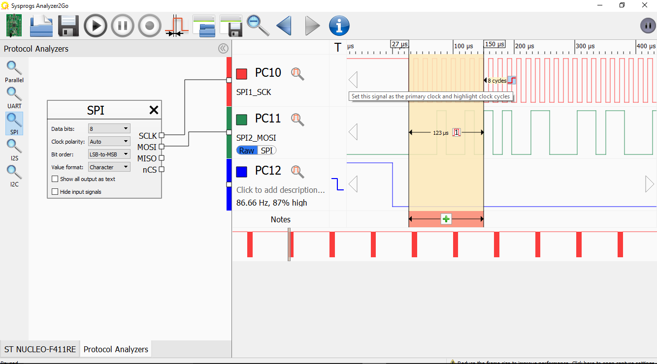
- Then switch the MOSI signal view from SPI to Raw to see the exact bits that correspond to the ‘H’ byte:
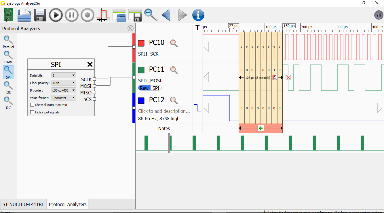
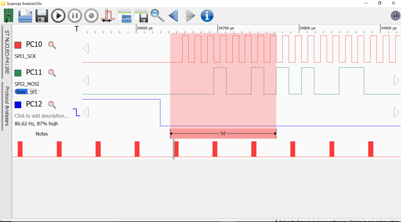
- Each of the 8 clock cycles transfers exactly 1 bit of the 8-byte character (MOSI will be low if the bit value is ‘0’ and high if the bit value is ‘1’). To visualize this, select the SCK clock cycles corresponding to the ‘H’ character and click ‘Set this signal as the primary clock’:
- Analyzer2Go will automatically print the value of MOSI in each clock cycle. As we are transferring the least significant bit first, 00010010 corresponds to 0b01001000 that is equal to 0x48 or the ASCII code for the capital ‘H’ character:
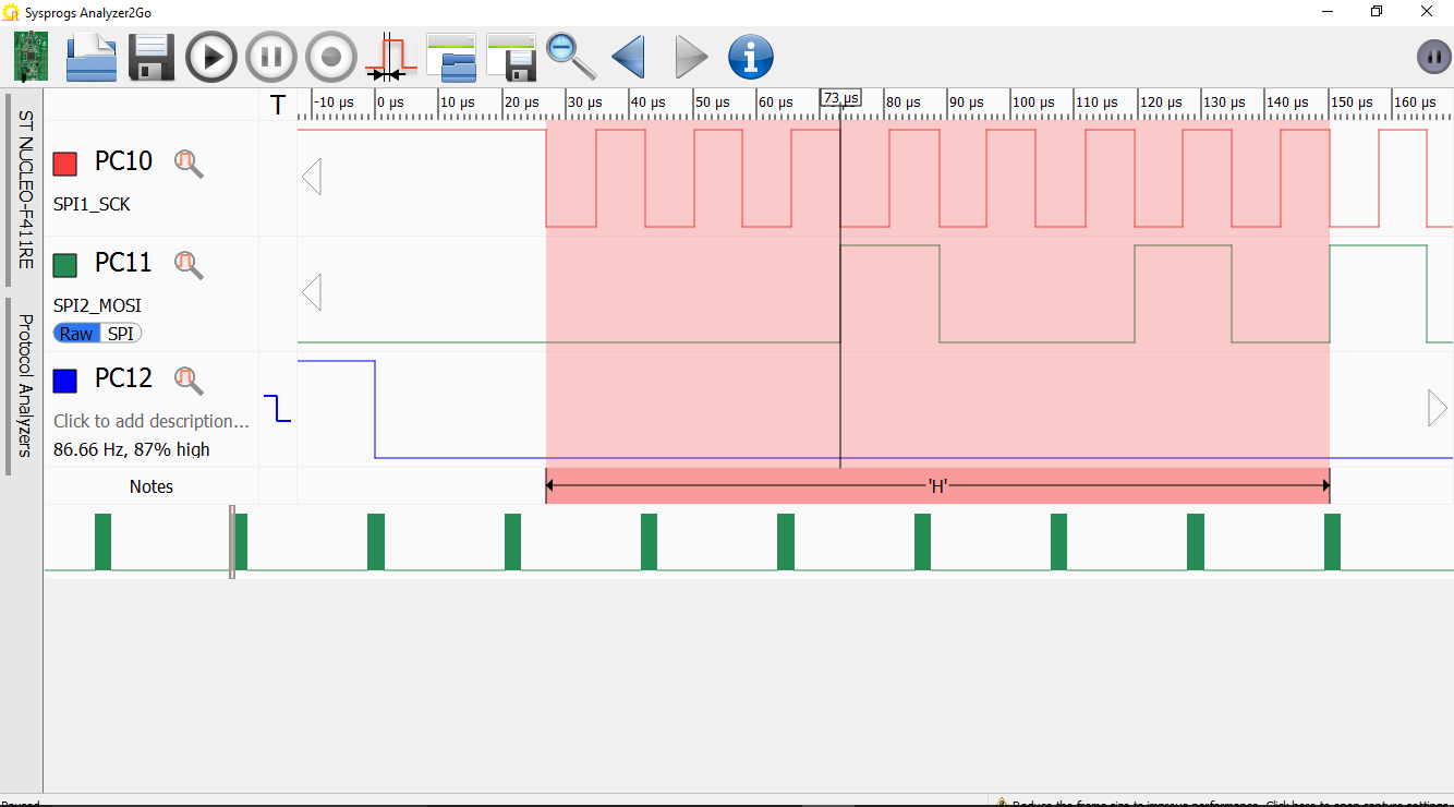
- Note that when the MOSI signal needs to change, it changes exactly at the falling clock edge of SCK. It ensures that the signal will have enough time (1/2 cycle) to stabilize by the time the receiving SPI device actually samples it:
- To change this behavior, set the CLKPolarity field of the SPI initialization structure to SPI_POLARITY_LOW instead:
spi.Init.CLKPolarity = SPI_POLARITY_LOW;
- Observe how the MOSI value now changes on the rising edge of SCLK:
 The correct value to use depends on the specifications of the device you want to interface over SPI. If it samples the MOSI output on rising edges, configure the SPI peripheral to change its value on falling edges. Otherwise set it to change at rising clock edges.
 - Another important parameter is the clock phase. It affects the state of the SCK signal when no transmission is active. Note that toggling the clock phase also changes the active edge:
CLKPolarity CLKPhase MOSI changes on SCK value when inactive SPI_POLARITY_HIGH SPI_PHASE_2EDGE Falling Edge High SPI_POLARITY_LOW SPI_PHASE_2EDGE Rising Edge Low SPI_POLARITY_LOW SPI_PHASE_1EDGE Falling Edge Low SPI_POLARITY_HIGH SPI_PHASE_1EDGE Rising Edge High Set CLKPhase to SPI_PHASE_1EDGE and observe how the signals change:
spi.Init.CLKPhase = SPI_PHASE_2EDGE;
- Now we will show how to configure the SPI peripheral to automatically control the NSS signal. Normally the slave SPI devices will ignore any SPI communication that takes place when their NSS input is inactive (set to 1). This allows sharing the same MOSI, MISO and SCK signals between several slave devices and using the NSS signals (1 for each device) to select which device should be responding to each communication. So far we have been controlling NSS manually using the HAL_GPIO_WritePin() function, however the STM32 SPI peripheral allows generating the NSS signal automatically. Change the initialization code accordingly:
    spi.Init.NSS = SPI_NSS_HARD_OUTPUT;
    //...
    GPIO_InitStruct.Pin  = GPIO_PIN_4;
    GPIO_InitStruct.Mode = GPIO_MODE_AF_PP;
    HAL_GPIO_Init(GPIOA, &GPIO_InitStruct);
Finally remove the calls to HAL_GPIO_WritePin().
- Run the code and observe the new signals. Note how NSS stays low during and between the transmissions:
- The only way to override this behavior while still using the hardware NSS mode is to disable the SPI peripheral after each transmission:
    for (;;)
    {
        HAL_SPI_Init(&spi);
        HAL_SPI_Transmit(&spi, (uint8_t *)message, strlen(message), HAL_MAX_DELAY);
        HAL_SPI_DeInit(&spi);
        HAL_Delay(10);
    }
- Run the updated code and confirm that the NSS signal reappears:
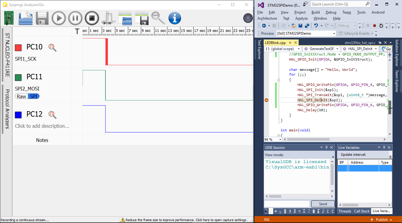
- We will now step through the HAL_SPI_DeInit() function to see at which point the NSS goes from 0 to 1. Stop your code at a breakpoint and click the “Record” button in the Analyzer2Go to begin recording the signal values continuously, then step into and through HAL_SPI_DeInit():
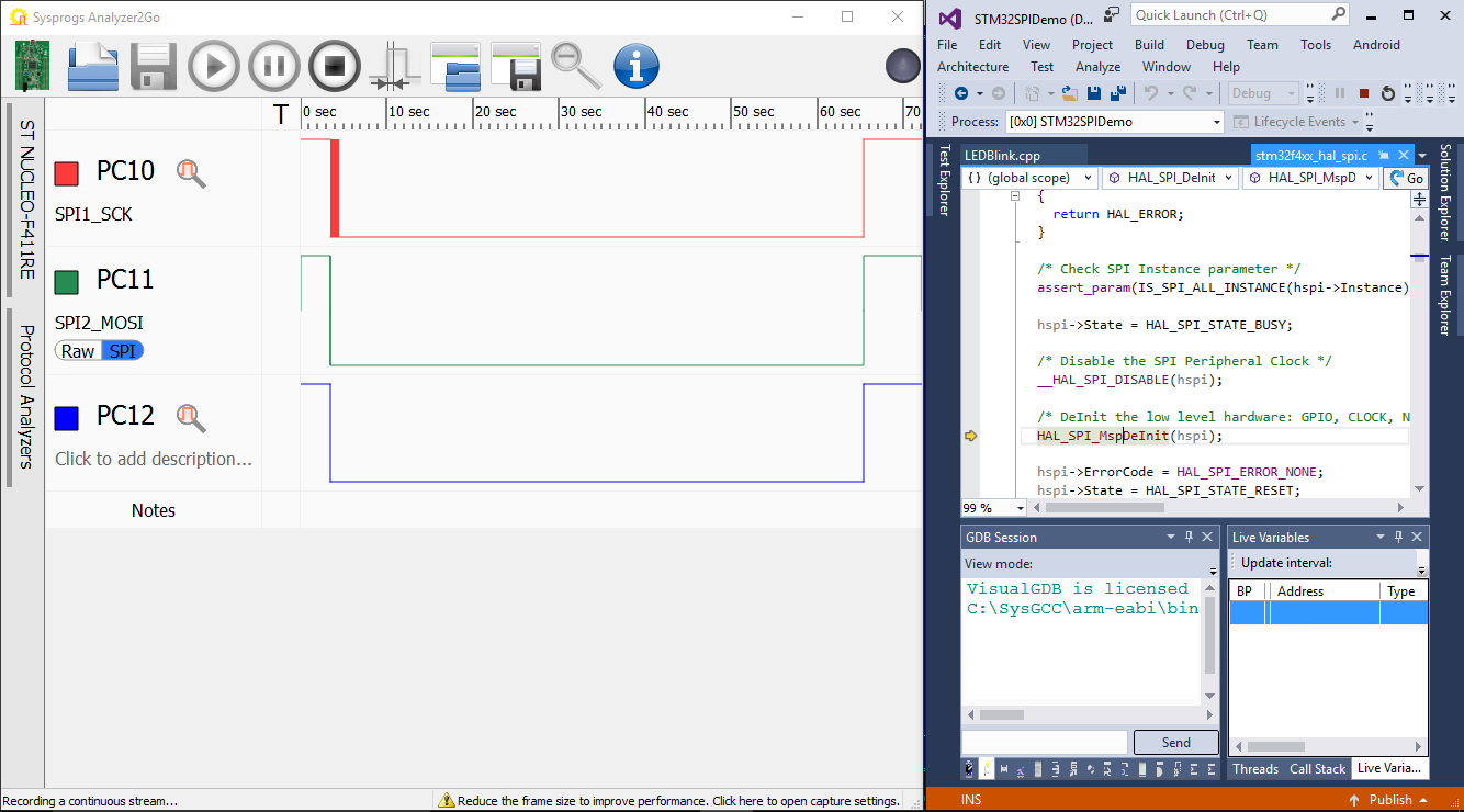
- The NSS signal will go from 0 to 1 once the __HAL_SPI_DISABLE(hspi) line gets executed:
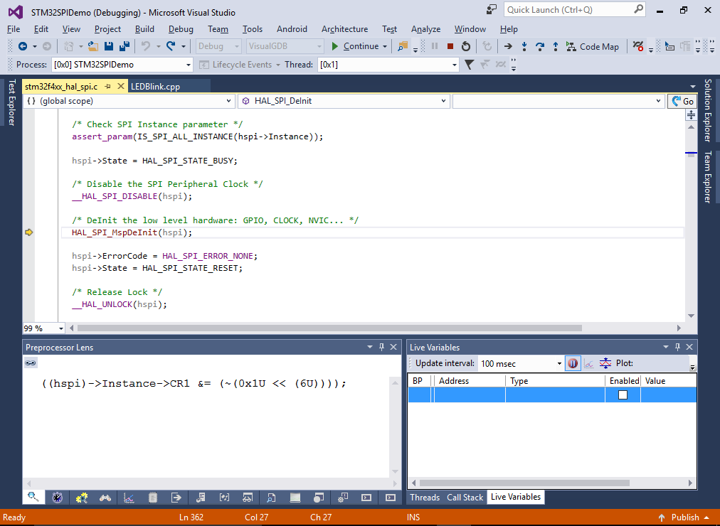
- Use the “Preprocess selected lines” command to see that it actually clears the bit #6 (SPE) in the SPI_CR register:
- The STM32 SPI peripheral also supports a special TI mode. Try switching it on by modifying the startup code as follows:
spi.Init.TIMode = SPI_TIMODE_DISABLED;
Note how the NCS signal now stays at 1 during once cycle before the transmission and then gets back to 0 (the bit order is also switched to MSB-first):
- Now we will show how to use the STM32 SPI to efficiently transfer large amounts of data (e.g. a stream of values to a digital-to-analog converter). First we will try the simplest approach: generate a block of values, then simply transmit it via HAL_SPI_Transmit():
#include <string.h>

unsigned s_TransferBuffer[256];

void FillNextFrame()
{
    static int s_FrameCounter = 0;
    for (int i = 0; i < sizeof(s_TransferBuffer) / sizeof(s_TransferBuffer[0]); i++)
        s_TransferBuffer[i] = (s_FrameCounter << 8) | (i & 0xFF);
    s_FrameCounter++;
}

void GenerateTestSPISignal()
{
    __GPIOA_CLK_ENABLE();
    __SPI1_CLK_ENABLE();

    static SPI_HandleTypeDef spi = { .Instance = SPI1 };
    spi.Init.BaudRatePrescaler = SPI_BAUDRATEPRESCALER_256;
    spi.Init.Direction = SPI_DIRECTION_2LINES;
    spi.Init.CLKPhase = SPI_PHASE_1EDGE;
    spi.Init.CLKPolarity = SPI_POLARITY_LOW;
    spi.Init.CRCCalculation = SPI_CRCCALCULATION_DISABLED;
    spi.Init.DataSize = SPI_DATASIZE_8BIT;
    spi.Init.FirstBit = SPI_FIRSTBIT_LSB;
    spi.Init.NSS = SPI_NSS_HARD_OUTPUT;
    spi.Init.TIMode = SPI_TIMODE_DISABLED;
    spi.Init.Mode = SPI_MODE_MASTER;
    if (HAL_SPI_Init(&spi) != HAL_OK)
    {
        asm("bkpt 255");
    }

    GPIO_InitTypeDef  GPIO_InitStruct;

    GPIO_InitStruct.Pin       = GPIO_PIN_5 | GPIO_PIN_6 | GPIO_PIN_7;
    GPIO_InitStruct.Mode      = GPIO_MODE_AF_PP;
    GPIO_InitStruct.Pull      = GPIO_PULLUP;
    GPIO_InitStruct.Speed     = GPIO_SPEED_HIGH;
    GPIO_InitStruct.Alternate = GPIO_AF5_SPI1;

    HAL_GPIO_Init(GPIOA, &GPIO_InitStruct);

    GPIO_InitStruct.Pin  = GPIO_PIN_4;
    HAL_GPIO_Init(GPIOA, &GPIO_InitStruct);

    for (;;)
    {
        FillNextFrame();
        HAL_SPI_Transmit(&spi, (uint8_t *)s_TransferBuffer, sizeof(s_TransferBuffer), HAL_MAX_DELAY);
    }
}
FillNextFrame() will fill the transfer buffer with 32-bit values starting from (FrameNumber * 0x100) to (FrameNumber * 0x100 + 0xFF). This allows telling the frame and the position within the frame from the value. E.g. 0x002501 means value #01 (starting from #00) in frame 0x25.
- Run the updated code. As FillNextFrame() and HAL_SPI_Transmit() cannot run at the same time, you will see gaps between the values corresponding to different frames:
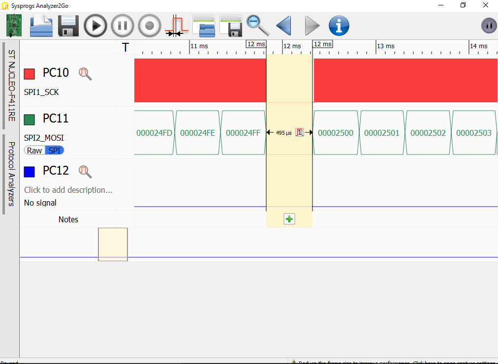
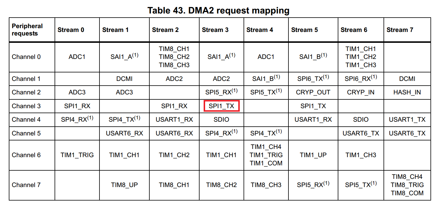
- To eliminate the gaps, we will configure the SPI to use DMA (direct memory access) with double-buffering. It will automatically transfer the first half of the buffer while your code will be filling the second half and vice versa, resulting in a 100% uninterrupted transmission. First locate the DMA channel and stream that is connected to the SPI1 TX channel:
- Then replace the code after the last call to HAL_GPIO_Init() by the code initializing and starting the DMA:
    __DMA2_CLK_ENABLE();
    s_DMA.Init.Channel = DMA_CHANNEL_3;
    s_DMA.Init.Direction = DMA_MEMORY_TO_PERIPH;
    s_DMA.Init.PeriphInc = DMA_PINC_DISABLE;
    s_DMA.Init.MemInc = DMA_MINC_ENABLE;
    s_DMA.Init.Mode = DMA_CIRCULAR;
    s_DMA.Init.PeriphDataAlignment = DMA_PDATAALIGN_BYTE;
    s_DMA.Init.MemDataAlignment = DMA_MDATAALIGN_BYTE;
    if (HAL_DMA_Init(&s_DMA) != HAL_OK)
        asm("bkpt 255");

    __HAL_LINKDMA(&spi, hdmatx, s_DMA);

    HAL_NVIC_EnableIRQ(DMA2_Stream5_IRQn);
    if (HAL_SPI_Transmit_DMA(&spi, (uint8_t *)s_TransferBuffer, sizeof(s_TransferBuffer)) != HAL_OK)
        asm("bkpt 255");

    for (;;)
        ;
- Then add the following code before the GenerateTestSPISignal() function:
DMA_HandleTypeDef s_DMA = { .Instance = DMA2_Stream5 };

extern "C" void DMA2_Stream5_IRQHandler()
{
    HAL_DMA_IRQHandler(&s_DMA);
}

static int s_FrameCounter = 0;

void HAL_SPI_TxHalfCpltCallback(SPI_HandleTypeDef *hspi)
{
    for (int i = 0; i < sizeof(s_TransferBuffer) / sizeof(s_TransferBuffer[0]) / 2; i++)
        s_TransferBuffer[i] = (s_FrameCounter << 8) | (i & 0xFF);
}

void HAL_SPI_TxCpltCallback(SPI_HandleTypeDef *hspi)
{
    for (int i = sizeof(s_TransferBuffer) / sizeof(s_TransferBuffer[0]) / 2; i < sizeof(s_TransferBuffer) / sizeof(s_TransferBuffer[0]); i++)
        s_TransferBuffer[i] = (s_FrameCounter << 8) | (i & 0xFF);
    s_FrameCounter++;
}
- By using HAL_SPI_Transmit_DMA() instead of HAL_SPI_Transmit() we tell the SPI peripheral to start transmitting s_TransferBuffer using the background direct memory access mechanism and immediately return control. When the first half of the buffer is transmitted, the DMA will raise an interrupt resulting in a call to HAL_SPI_TxHalfCpltCallback() that will generate the first half of the next frame while the current frame is still being transferred. When the entire buffer is transferred, HAL_SPI_TxCpltCallback() will get called and will generate the second half of the frame (while the DMA is already sending the first half of it). This results in 100% uninterrupted transmission without any gaps:
- You can visualize the transfer timings by replacing the empty loop at the end of GenerateTestSPISignal() with the loop toggling the NSS signal (don’t forget to configure PA4 as GPIO_MODE_OUTPUT_PP):
    for (;;)
        HAL_GPIO_TogglePin(GPIOA, GPIO_PIN_4);
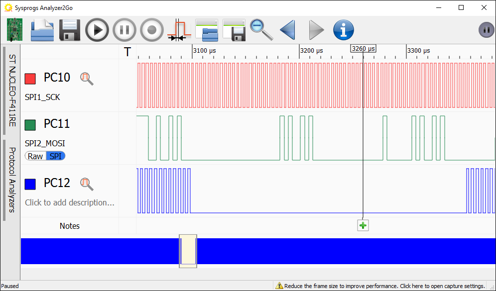
- Run the updated code. Observe how the NSS signal value stops changing for a short time (while one of the CpltCallback functions is running), but the SPI transmission runs uninterrupted:
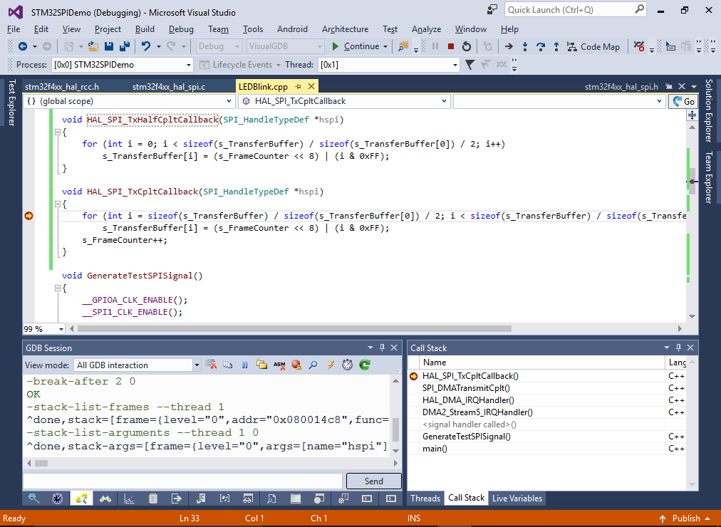
- You can set a breakpoint in one of the CpltCallback functions and use the Call Stack window to see the chain of functions involved in handling the interrupt: