Controlling STM32 Hardware Timers with Interrupts
This tutorial shows how control the hardware timers of an STM32 microcontroller. We will show it based on the STM32F4-Discovery board, however controlling the timers of other STM32 devices is very similar.
Warning: this tutorial describes the legacy StdPeriph interface. To learn about controlling the timers using the new HAL interface, follow this tutorial instead.
Before you begin with this tutorial please create a basic project for your STM32 device (e.g. by following this tutorial for STM32F1 series devices or this tutorial for the STM32F4-Discovery board).
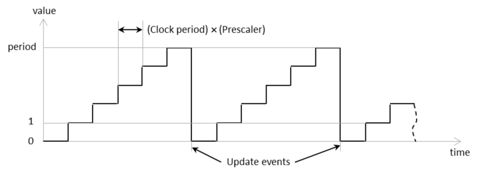
- A hardware timer is essentially an independent counter that counts from zero to its maximum value at a given speed and generates various events. It runs in the background independently from your C/C++ program and its value typically follows the sequence depicted below:
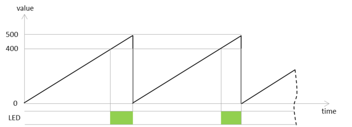
- Let’s start with a simple program that will configure the timer to run in the background with a period of 500, turn the LED on once the value reaches 400 and back off once it gets to 500. The timer will automatically reset itself to zero once it reaches a value of 500:
- We will initialize the timer to run with a prescaler of 40000, and a period of 500. Note that before we can do anything with the timer we need to enable it by calling RCC_APB1PeriphClockCmd():
RCC_APB1PeriphClockCmd(RCC_APB1Periph_TIM2, ENABLE);

TIM_TimeBaseInitTypeDef timerInitStructure;
timerInitStructure.TIM_Prescaler = 40000;
timerInitStructure.TIM_CounterMode = TIM_CounterMode_Up;
timerInitStructure.TIM_Period = 500;
timerInitStructure.TIM_ClockDivision = TIM_CKD_DIV1;
timerInitStructure.TIM_RepetitionCounter = 0;
TIM_TimeBaseInit(TIM2, &timerInitStructure);
TIM_Cmd(TIM2, ENABLE);
- In the main() function we will simply check the timer value and control the LED based on it. The entire program for the STM32F4-Discovery board is listed below:
#include <stm32f4xx_gpio.h>
#include <stm32f4xx_tim.h>
#include <stm32f4xx_rcc.h>
#include <misc.h>

void InitializeLEDs()
{
    RCC_AHB1PeriphClockCmd(RCC_AHB1Periph_GPIOD, ENABLE);

    GPIO_InitTypeDef gpioStructure;
    gpioStructure.GPIO_Pin = GPIO_Pin_12 | GPIO_Pin_13;
    gpioStructure.GPIO_Mode = GPIO_Mode_OUT;
    gpioStructure.GPIO_Speed = GPIO_Speed_50MHz;
    GPIO_Init(GPIOD, &gpioStructure);

    GPIO_WriteBit(GPIOD, GPIO_Pin_12 | GPIO_Pin_13, Bit_RESET);
}

void InitializeTimer()
{
    RCC_APB1PeriphClockCmd(RCC_APB1Periph_TIM2, ENABLE);

    TIM_TimeBaseInitTypeDef timerInitStructure;
    timerInitStructure.TIM_Prescaler = 40000;
    timerInitStructure.TIM_CounterMode = TIM_CounterMode_Up;
    timerInitStructure.TIM_Period = 500;
    timerInitStructure.TIM_ClockDivision = TIM_CKD_DIV1;
    timerInitStructure.TIM_RepetitionCounter = 0;
    TIM_TimeBaseInit(TIM2, &timerInitStructure);
    TIM_Cmd(TIM2, ENABLE);
}

int main()
{
    InitializeLEDs();
    InitializeTimer();

    for (;;)
    {
        int timerValue = TIM_GetCounter(TIM2);
        if (timerValue == 400)
            GPIO_WriteBit(GPIOD, GPIO_Pin_12, Bit_SET);
        else if (timerValue == 500)
            GPIO_WriteBit(GPIOD, GPIO_Pin_12, Bit_RESET);
    }
}
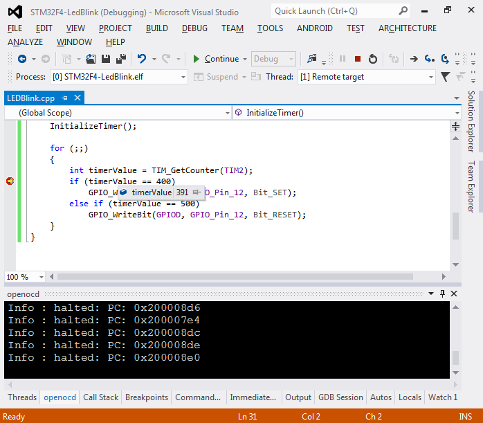
- Run the program and notice how LED blinks in short cycles. If you set a breakpoint after the line reading timerValue, you will see that each time it is hit the timerValue will be between 0 and 500. This corresponds to the period of 5000 we have specified in TIM_Period:
- The STM32 timers can automatically generate ‘update’ events once they reach the period value. Add the following code after the TIM_Cmd(TIM2, ENABLE) line:
TIM_ITConfig(TIM2, TIM_IT_Update, ENABLE);
- This will enable the ‘update’ interrupt for the timer. Note that as we did not configure interrupt controller, the interrupt won’t affect our code execution and we’ll have to check for it manually. Replace the contents of main() with the following code:
InitializeLEDs();
InitializeTimer();
for (;;)
{
    if (TIM_GetITStatus(TIM2, TIM_IT_Update) != RESET)
    {
        TIM_ClearITPendingBit(TIM2, TIM_IT_Update);
        GPIO_ToggleBits(GPIOD, GPIO_Pin_12);
    }
}
Run the program and notice how the LED blinking pattern has changed. Now instead of polling the timer value constantly and switching the LED on and off on certain threshold values we simply wait for the TIM_IT_Update interrupt and toggle the LED once it arrives.
- The real power of hardware timers is however in the way they can send interrupts to the CPU eliminating the need to check the status manually. Add the following function to your code and call it from main() after InitializeTimer():
void EnableTimerInterrupt() { NVIC_InitTypeDef nvicStructure; nvicStructure.NVIC_IRQChannel = TIM2_IRQn; nvicStructure.NVIC_IRQChannelPreemptionPriority = 0; nvicStructure.NVIC_IRQChannelSubPriority = 1; nvicStructure.NVIC_IRQChannelCmd = ENABLE; NVIC_Init(&nvicStructure); } - Finally remove all contents of the for(;;) loop in main() and move it into the TIM2_IRQHandler() function:
extern "C" void TIM2_IRQHandler()
{
    if (TIM_GetITStatus(TIM2, TIM_IT_Update) != RESET)
    {
        TIM_ClearITPendingBit(TIM2, TIM_IT_Update);
        GPIO_ToggleBits(GPIOD, GPIO_Pin_12);
    }
}
Note that you only need extern “C” if you are building a C++ program.
- Run your new program and observe how the LED blinks. Put a breakpoint inside TIM2_IRQHandler() and observe the register values:
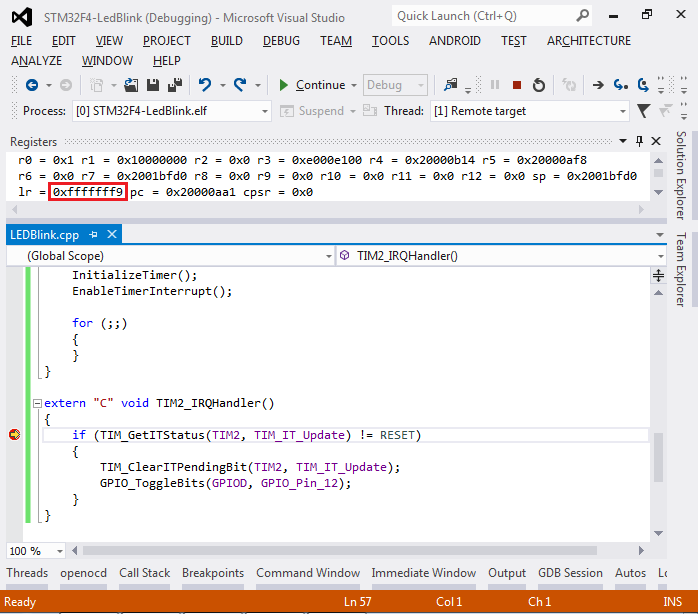
- Note that the link register (lr) that normally contains the return address of a function contains the value of 0xfffffff9. This is a special value denoted as EXC_RETURN in ARM Cortex CPU documentation. It means that the current function was called by the CPU automatically as a result of handling an exception.
- Replace the contents of the for(;;) loop in main() with the following:
for (int i = 0; i < 1000000; i++)
    asm("nop");
GPIO_ToggleBits(GPIOD, GPIO_Pin_13);
- Run your program. You will see how the two LEDs blink with different frequencies independently. The loop inside main() that controls the orange LED does not need to do any extra checks to control the green LED. The timer automatically pauses it and transfers control to TIM2_IRQHandler() each time an update event occurs.
- Note that the name of the TIM2_IRQHandler() function is crucial to the entire process of handling interrupts. The STM32 startup file contains the following code:
void TIM2_IRQHandler() __attribute__ ((weak, alias ("Default_Handler")));

void *g_pfnVectors[0x62] __attribute__ ((section (".isr_vector"))) =
{
    &_estack,
    &Reset_Handler,
    &NMI_Handler,
    ... ,
    &TIM2_IRQHandler,
    ... ,
}

void__attribute__((naked, noreturn)) Default_Handler()
{
    for (;;) ;
}
The g_pfnVectors table contains addresses of interrupt handlers such as TIM2_IRQHandler(). Furthermore, unless you explicitly provide a method for a given interrupt handler, such as TIM2_IRQHandler(), GCC will automatically substitute it with DefaultHandler() that will halt your program.


You can download the full source code of this sample here: TimerDemo.cpp
To learn about controlling the STM32 timers using the HAL API, follow this tutorial.