Using the ESP32 Camera Interface from Arduino-based Projects
This tutorial shows how to create a basic project for the ESP32-CAM module and use the JTAG interface to debug it.
We will use VisualGDB to clone the ESP32 Arduino Camera example and then modify it to automatically take pictures in a loop and upload them via HTTP to a specified server. Before you begin, ensure you have installed Visual Studio and VisualGDB 5.4.
Wiring
In order to get JTAG debugging to work, we would need to connect the following pins of the ESP32-CAM module to a compatible JTAG debugger (e.g. Olimex ARM-USB-OCD-H or Segger J-Link):
| ESP-CAM Pin | JTAG signal | JTAG20 pin |
| 3.3V | +3.3V | 1 |
| GND | GND | 4 |
| GPIO12 | TDI | 5 |
| GPIO14 | TMS | 7 |
| GPIO13 | TCK | 9 |
| GPIO15 | TDO | 13 |
See the picture below for details (courtesy of Seeed Studio): As the ESP32-CAM board does not come with a USB connector, you would need to use an external 5V power source. In this tutorial we will use a Nucleo board from ST Microelectronics as a 5V source and will also use its 3.3V UART interface provided by the on-board ST-Link to receive the text output from the ESP32-CAM module. If you are using the Nucleo board, remove the JP5 jumper (powering the STM32 microcontroler on the board) and connect the GND, +5V and RX signals to the ESP32-CAM module as shown below:
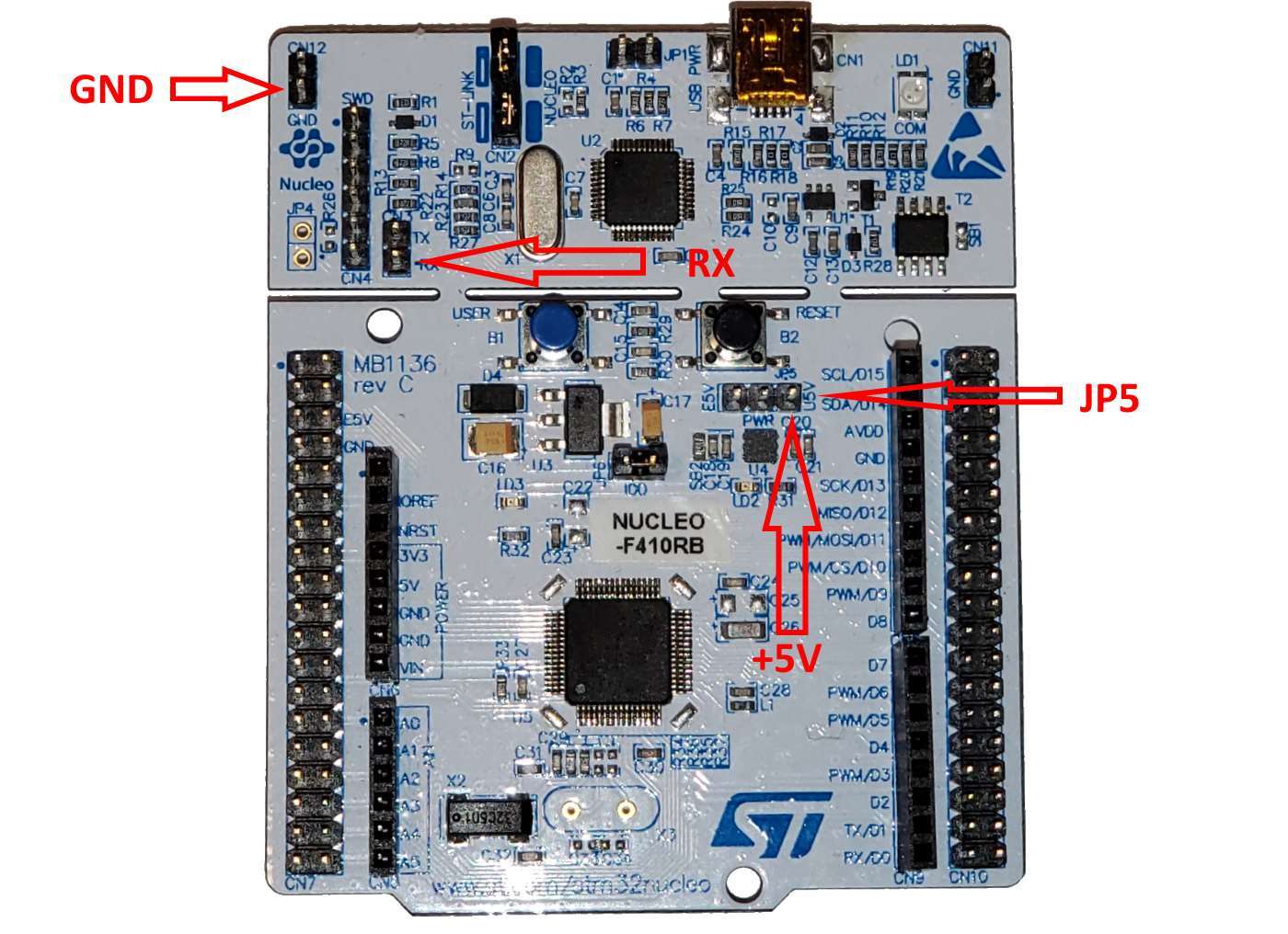
Note that due to the limitations of the ST-Link programmer, you won’t be able to use it to debug the ESP32 device and hence will need a low-level debug probe.
The final wiring setup used in this tutorial is shown below: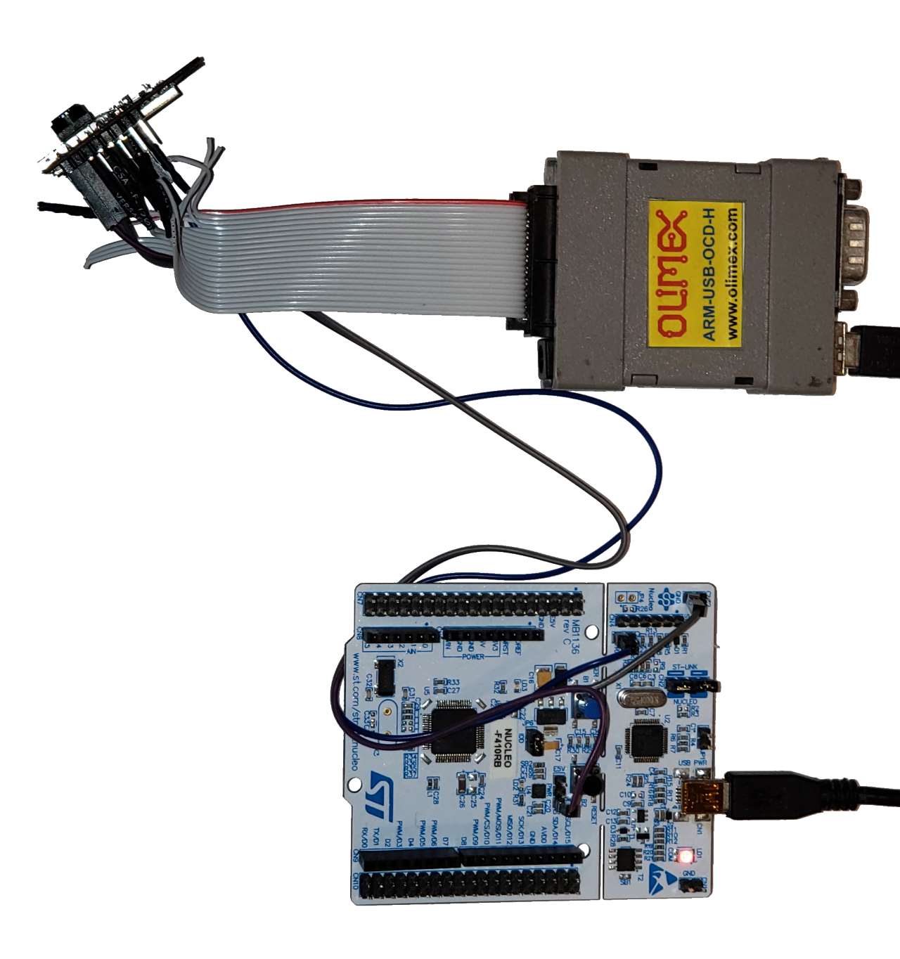 Note that the ST Nucleo board is used to provide the 5V signal and the Olimex ARM-USB-OCD-H debugger is used for the actual JTAG debugging.
Software Setup
Now that we are done with the wiring, we can start with the software configuration necessary to debug the ESP32-CAM board. Follow the steps below to create a basic project, step through it and modify it to automatically upload the taken pictures:
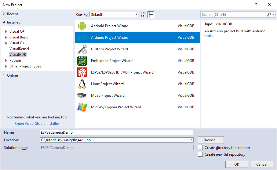
- The best ready-to-use ESP32 camera example is included in the ESP32 Arduino package, so we will use the Arduino workflow in this tutorial. As long as you are using VisualGDB 5.4 or later, it will automatically install the necessary tools and packages for you as you create the project. Hence start Visual Studio and open the VisualGDB Arduino Project Wizard:
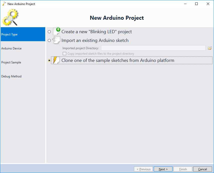
- As we will be starting with an existing camera example, select “Clone one of the sample sketches from Arduino platform”:
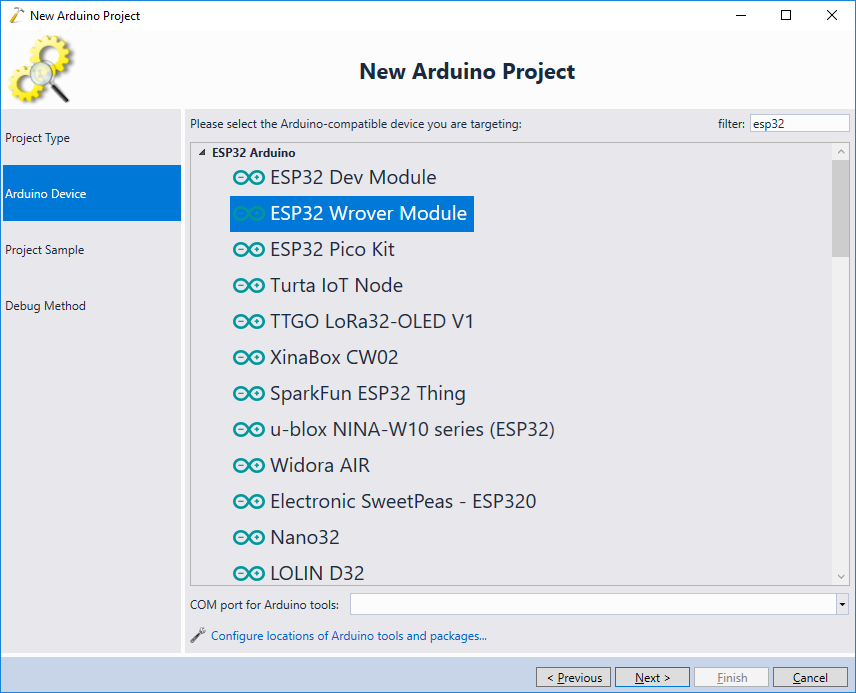
- The ESP32 Arduino platform does not have a special target for the ESP32-CAM module, however it is compatible with the ESP32 Wrover module. Simply select it from the list:
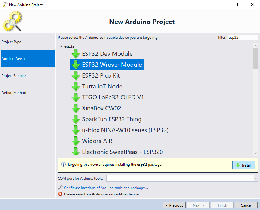
- If you have not created ESP32 Arduino projects before, click “Install” and VisualGDB will automatically download and install the necessary packages:
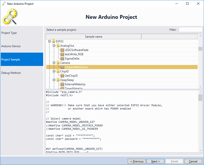
- In this tutorial we will clone the CameraWebServer sample provided by Espressif, so simply select it from the list:
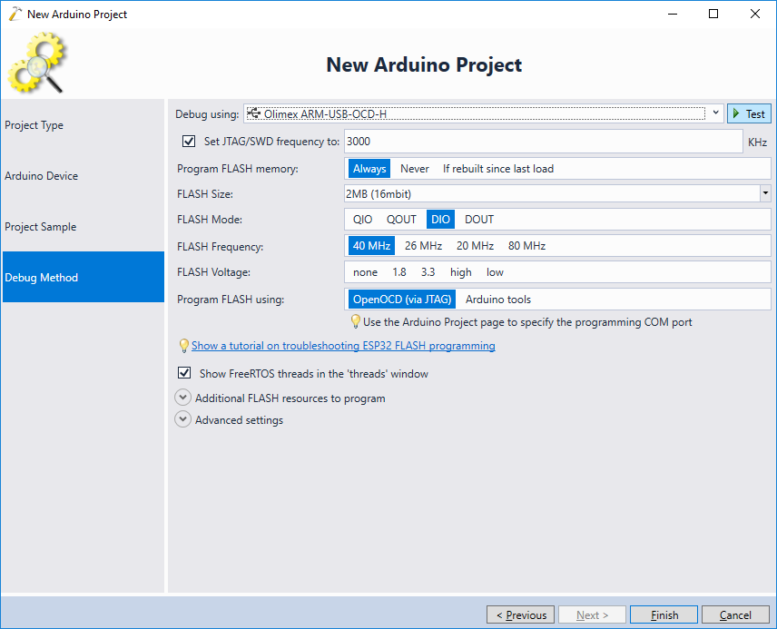
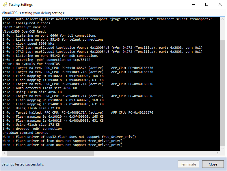
- Connect your JTAG debugger via USB and select it on the Debug Method page. Then click “Test” to verify the wiring:
- OpenOCD should confirm that it’s able to communicate to the ESP32 chip:
 Once the wiring is verified, press “Finish” to create the project.
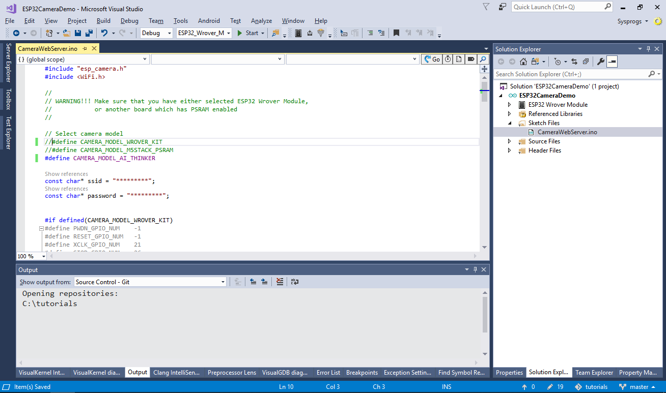
 - Before you can build the project, comment out the CAMERA_MODEL_WROVER_KIT definition and uncomment the CAMERA_MODEL_AI_THINKER line to enable the pinout specific to the board you are using:
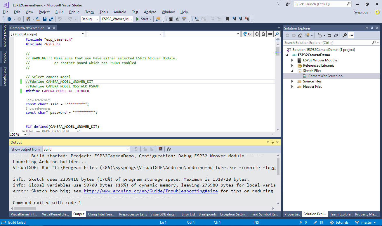
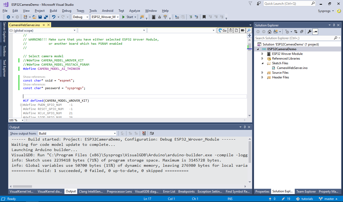
- If you try building the project now, the Arduino tools will fail stating that the sketch is too big:
- This happens because the default partition configuration is too small to fit the camera example. Open VisualGDB Project Properties and change the Partition Scheme to Huge APP:
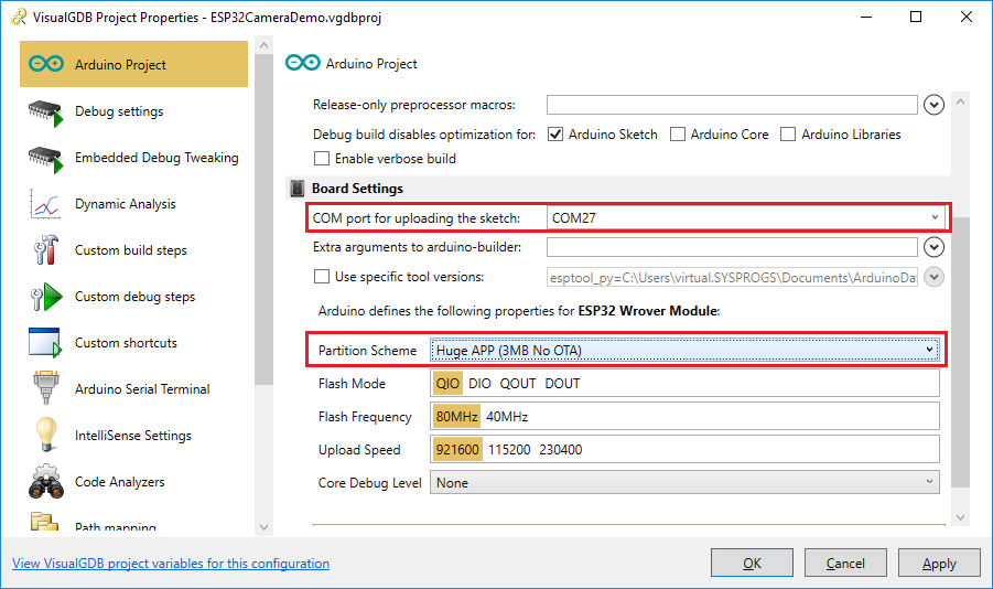 If you have connected the serial output of the ESP32-CAM module to the ST Nucleo board (or another UART-to-USB adapter), select its COM port in the “COM port for uploading the sketch” field. If not, leave the field empty. As ESP32 projects are programmed via JTAG, the COM port is not actually necessary, although it’s useful for viewing the diagnostic output.
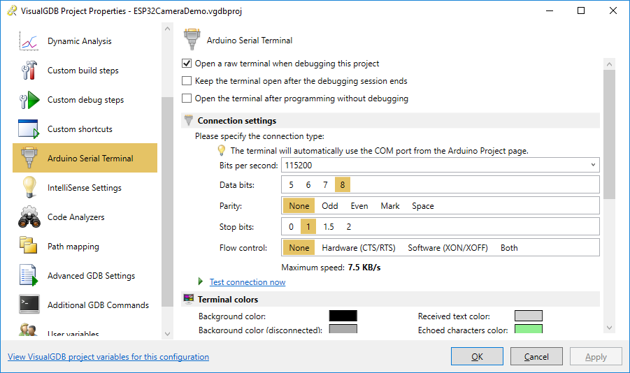
 - If you have connected the serial port, go to the Arduino Serial Terminal page of VisualGDB Project Properties and check the “Open a raw terminal” checkbox:
- Finally, set the ssid and password variables at the beginning of the sketch to match your network configuration. Then press Ctrl-Shift-B to build the project:
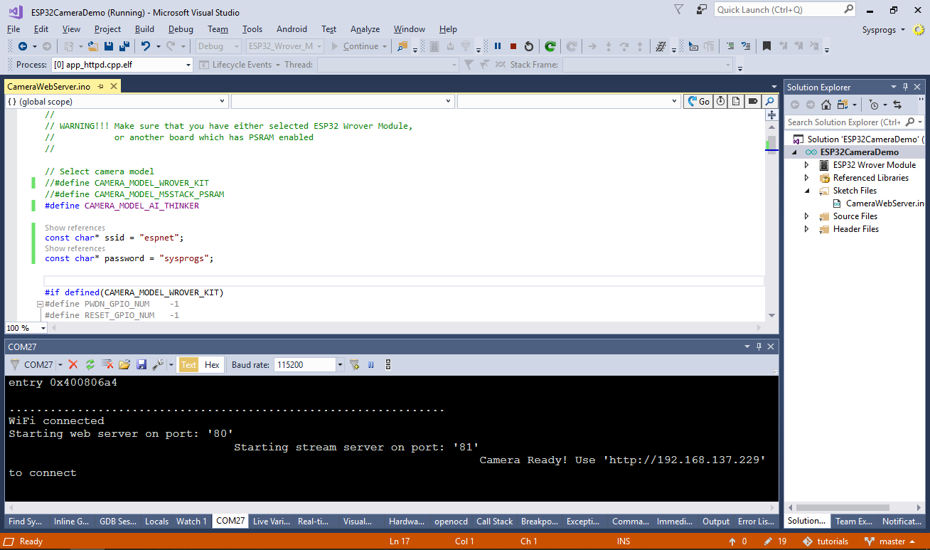
- Start debugging by pressing F5. VisualGDB will automatically program the FLASH memory and start the program. If you have connected the serial output of the module, you will see the IP address of the camera displayed there:
 If you are not using a serial port, set a breakpoint inside the WiFiSTAClass::localIP() function before starting the debugger and then evaluate the “ip” expression to check the IP address assigned to the board.
 - Go to the IP address of the board in your browser. You will see a basic web interface provided by the Arduino sample that lets you set various parameters and take pictures:

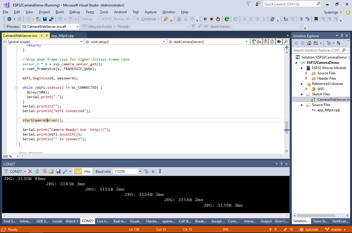
- Now we will use the code navigation functions of VisulaGDB and the debugger to understand the components involved in taking the pictures and sending them to the browser. First of all, go to the definition of the startCameraServer() function:
- The startCameraServer() function defines several handlers for various pages of the built-in web server. Opening the “/capture” page results in capturing one frame from the camera and outputting it via HTTP. Select the capture_handler function and click “Go to definition” to view its source:

- Set a breakpoint inside the capture_handler() function and try capturing a single frame from the browser. The breakpoint will trigger, allowing you to check the captured frame parameters:
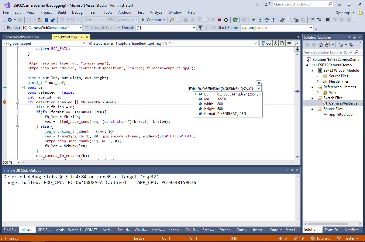
- You can use the Memory window to verify that the bb->buf buffer contains a properly encoded JPEG image (see the JFIF signature):
 From the code of the capture_handler() function we can reconstruct the steps involved in capturing pictures from the camera:
- esp_camera_fb_get() is used to get a single picture.
- esp_camera_fb_return() must be used to free the memory allocated by esp_camera_fb_get().
- The format of the captured picture will be stored in the format field of the structure returned by esp_camera_fb_get().
- The actual data will be stored in a buffer pointed by the buf field.
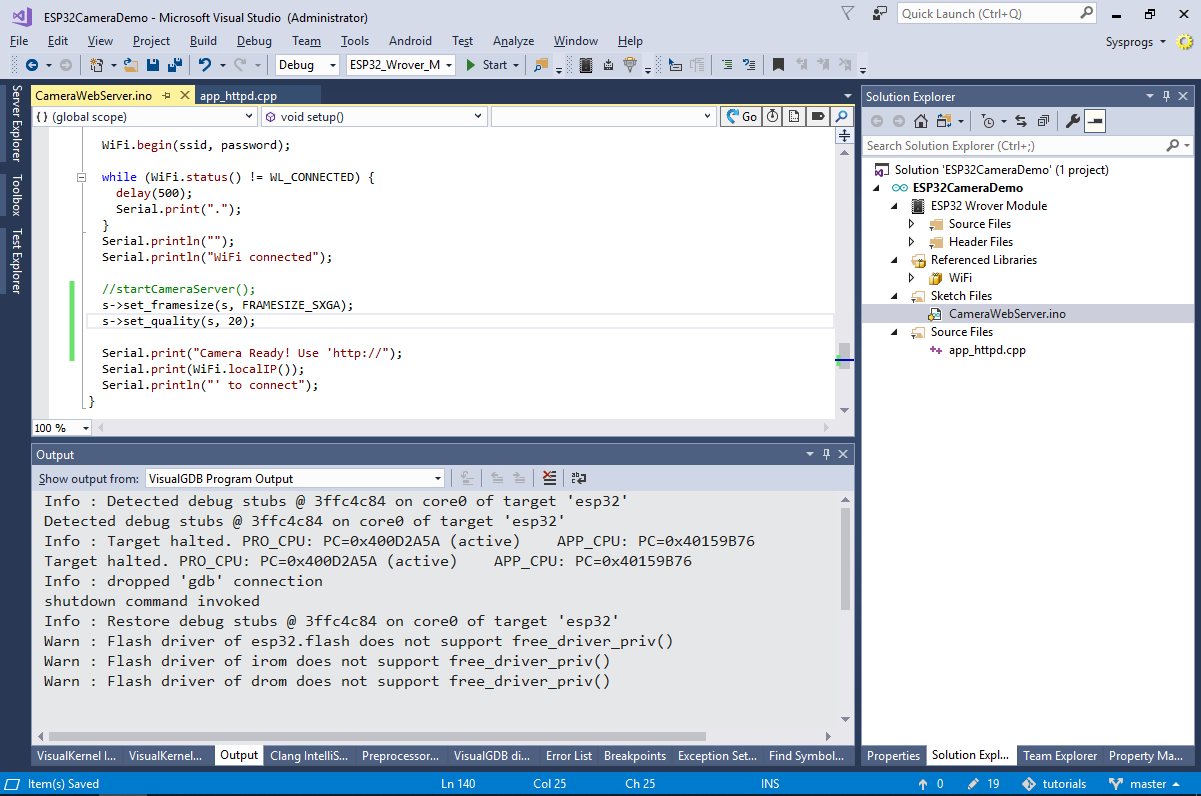
- We will now the example to automatically capture frames as fast as possible and upload them to an external server via HTTP. First of all, edit the setup() function to automatically set the frame size and quality and comment out the call to startCameraServer():
	s->set_framesize(s, FRAMESIZE_SXGA);
	s->set_quality(s, 20);
- Then include the <esp_http_client.h> file and replace the loop() function with the following code:
void loop()
{
	camera_fb_t *fb = NULL;
	esp_err_t res = ESP_OK;
	fb = esp_camera_fb_get();
	if (!fb)
	{
		Serial.println("Camera capture failed");
		esp_camera_fb_return(fb);
		return;
	}

        size_t fb_len = 0;
	if (fb->format != PIXFORMAT_JPEG)
	{
		Serial.println("Non-JPEG data not implemented");
		return;
	}

	esp_http_client_config_t config = {
		.url = "http://192.168.0.3:8888/upload",
	};

	esp_http_client_handle_t client = esp_http_client_init(&config);
	esp_http_client_set_post_field(client, (const char *)fb->buf, fb->len);
	esp_http_client_set_method(client, HTTP_METHOD_POST);
	esp_http_client_set_header(client, "Content-type", "application/octet-stream");
	esp_err_t err = esp_http_client_perform(client);
	if (err == ESP_OK)
		Serial.println("Frame uploaded");
	else
		Serial.printf("Failed to upload frame, error %d\r\n", err);

	esp_http_client_cleanup(client);

	esp_camera_fb_return(fb);
}
Also replace 192.168.0.3 with the address of your Windows machine.
- Now we will create a very basic Web server that will display the pictures received from the ESP32-CAM module. Create a new C# WPF Application in Visual Studio and replace the contents of the Window element in the XAML file with the following code:
    <Grid>
        <Image x:Name="img"/>
    </Grid>
Then add the following code to the MainWindow.cs file:
    public partial class MainWindow : Window
    {
        HttpListener _Listener = new HttpListener();

        public MainWindow()
        {
            _Listener.Prefixes.Add("http://192.168.0.3:8888/");
            _Listener.Start();
            InitializeComponent();
            new Thread(ThreadBody).Start();
        }

        void ThreadBody()
        {
            for (; ;)
            {
                HttpListenerContext context = _Listener.GetContext();
                byte[] receivedData = new byte[(int)context.Request.ContentLength64];
                int done = 0;
                for (; ; )
                {
                    int read = context.Request.InputStream.Read(receivedData, done, receivedData.Length - done);
                    if (read <= 0)
                        break;
                    done += read;
                }

                byte[] reply = System.Text.Encoding.UTF8.GetBytes("Done");
                context.Response.ContentLength64 = reply.Length;
                context.Response.OutputStream.Write(reply, 0, reply.Length);
                context.Response.OutputStream.Close();

                Dispatcher.BeginInvoke(new Action(() =>
                {
                    var imageSource = new BitmapImage();
                    imageSource.BeginInit();
                    imageSource.StreamSource = new MemoryStream(receivedData);
                    imageSource.EndInit();
                    img.Source = imageSource;
                }));
            }
        }
    }
Don’t forget to update the IP address inside the MainWindow.cs file and temporarily disable your firewall (or add port 8888 to exceptions).
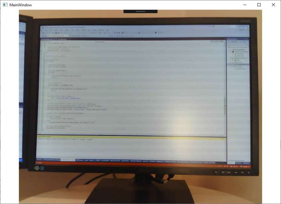
- Build and start the C# web server and run the modified Arduino sketch on the ESP32-CAM module. As soon as the board starts up, the web server will begin displaying the pictures it receives from the ESP32 camera:
You can modify the URL used in the Arduino sketch to upload the taken pictures into the cloud, or to any other location accessible to the board. You can limit the frame rate of this example bycalling the delay() function before exiting from loop().