Debugging Kendryte K210 Projects with Visual Studio
This tutorial shows how to create a basic “Blinking LED” project for the Kendryte K210 CPU and debug it with Visual Studio.
We will use the Sipeed M1 Dock board and will create a basic project controlling the on-board LCD. Before you begin, install Visual Studio and VisualGDB 5.4R12 or later.
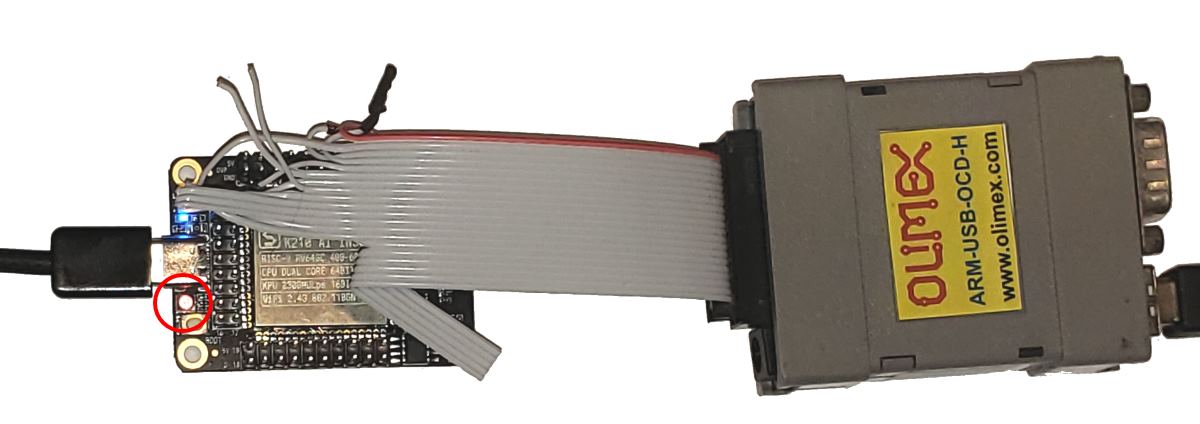
In order to debug the Kendryte K210 chip with JTAG, you will need to connect the following signals to your JTAG debugger (we recommend using Segger J-Link, Olimex ARM-USB-OCD-H or any other FTDI-based debugger):
| K210 Signal | Location on Sipeed MAIX Dock | JTAG signal | JTAG20 pin |
| VCC | VCC | 1 | |
| GND | GND | 4 | |
| TDI | 2 | TDI | 5 |
| TMS | 3 | TMS | 7 |
| TCK | 1 | TCK | 9 |
| TDO | 4 | TDO | 13 |
| RESET | SRST | 15 |
See the picture below for a list of all JTAG-related signals that need to be connected: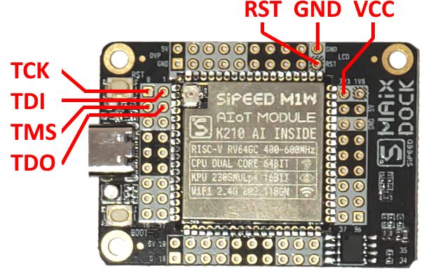 Once you get the JTAG signals connected, follow the steps below to create, build and debug a basic project.
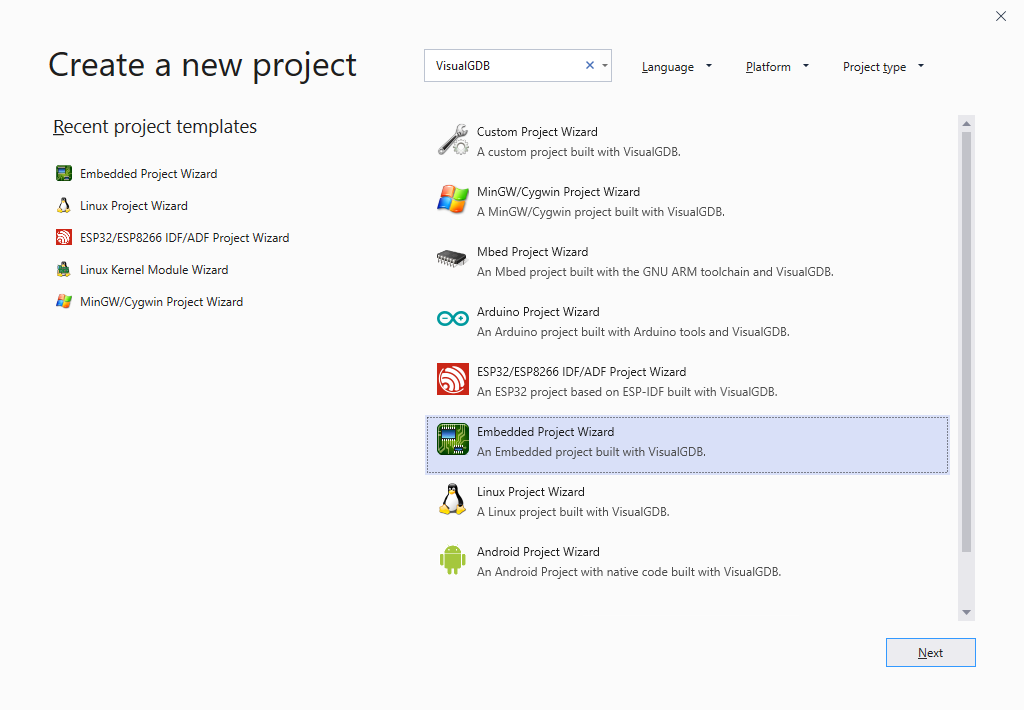
- Start Visual Studio and open the VisualGDB Embedded Project Wizard:
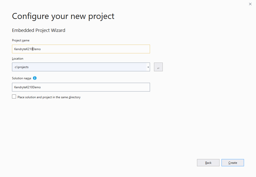
- Specify the name and location of the project you will be creating and press “Create” to launch the VisualGDB’s portion of the wizard:
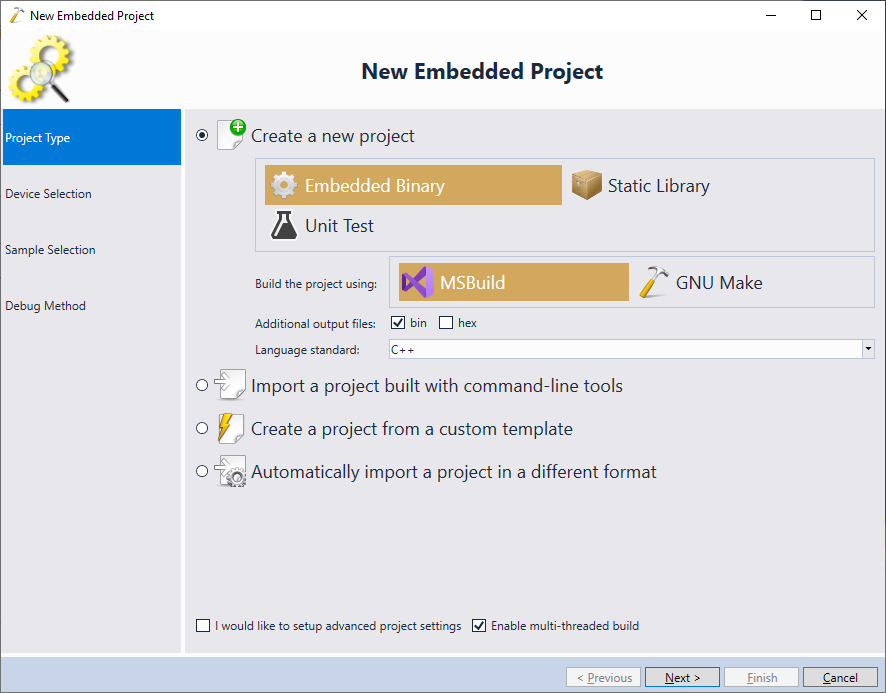
- On the first page of the VisualGDB’s wizard select “Create a new project -> Embedded Binary -> MSBuild”:
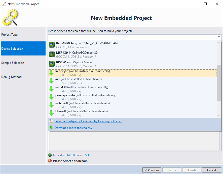
- On the next page pick the Kendryte toolchain (don’t use the generic RISC-V toolchain as it does not support Kendryte devices). If you haven’t installed the toolchain yet, VisualGDB will do it automatically:
- Select the K210 device and click “Next” to open the sample selection page:

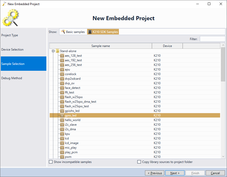
- VisualGDB allows quickly cloning project samples from both stand-alone and RTOS SDKs of K210. Switch the sample view to “K210 SDK Samples” and pick the gpio_led sample from the Stand-alone folder, then press “Next”:
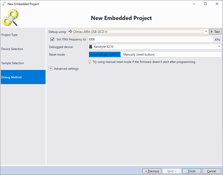
- Connect your JTAG debugger and the K210 board via USB and ensure you have all JTAG signals connected. VisualGDB should automatically detect and select the debug interface:
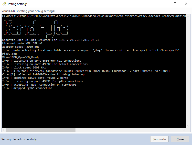
- Press the “Test” button. VisualGDB will launch the Kendryte port of OpenOCD, verifying that the connection between the JTAG debugger and the target is working:
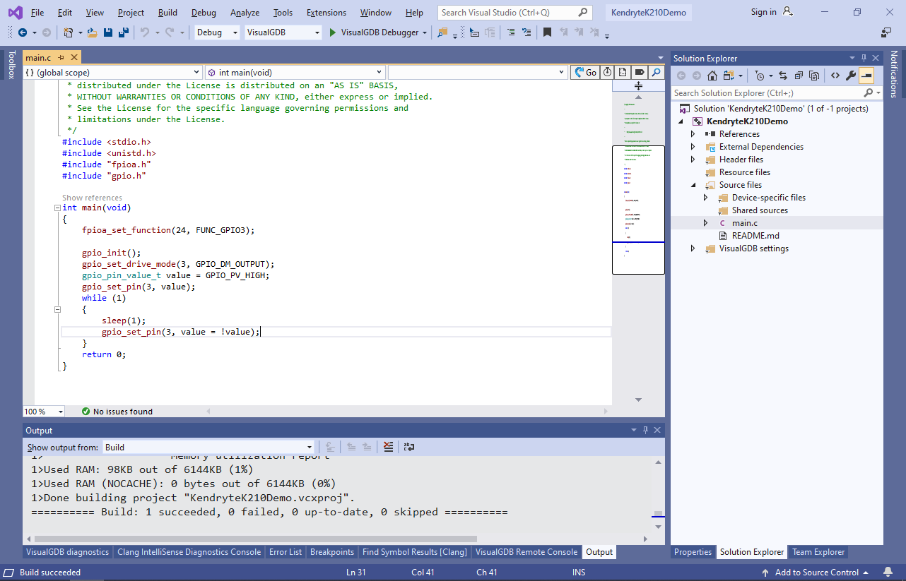
- Press “Finish” to create the project and ensure you can build it by pressing Ctrl-Shift-B:
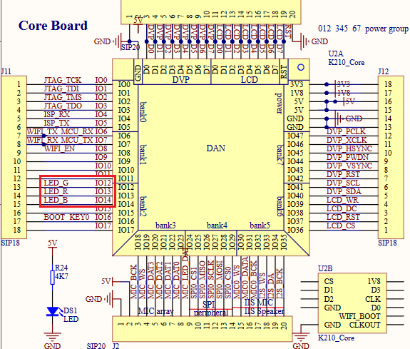
- Now we will modify the project to blink the on-board LED. Locate the schematics for your board (most of boards designed by Sipeed have their schematics available here) and identify the IO port number for the LED. The MAIX Suit board used in this example has the 3-color LED connected to IO12, IO13 and IO14:
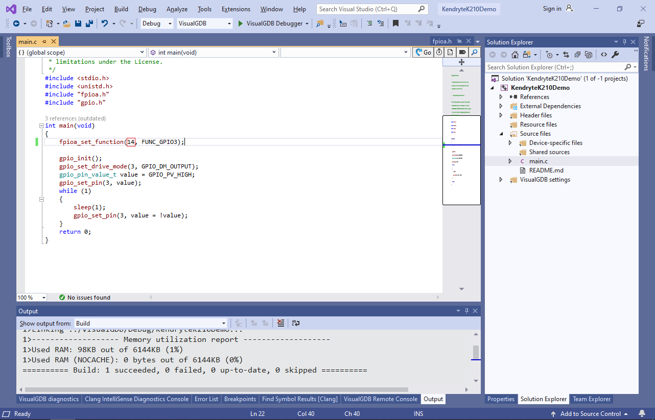
- Modify the fpioa_set_function() call to use the IO port that is connected to the LED. E.g. calling fpioa_set_function(14, FUNC_GPIO3) will associate the GPIO3 signal with the IO_14 pin, so the GPIO-related code can refer to it as GPIO pin #3:
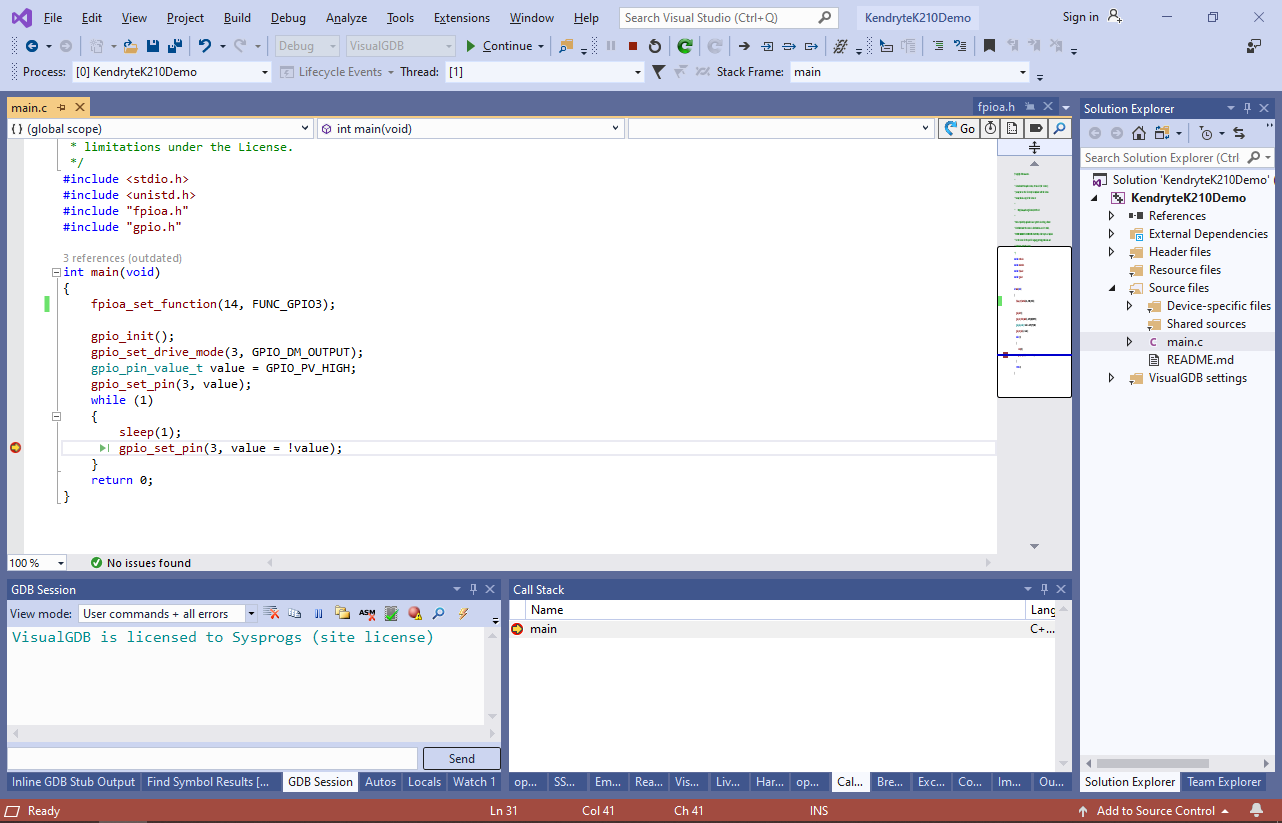
- Set a breakpoint in main() and press F5 to build the project again and begin debugging it. Wait for the breakpoint trigger:
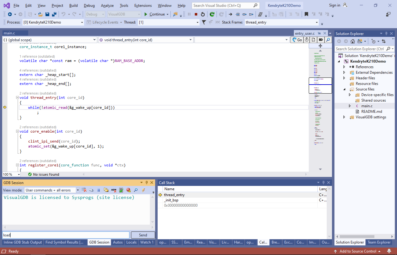
- The Kendryte OpenOCD fork that is needed to debug the K210 devices is less reliable than the original ARM-based fork and hence sometimes the program will not start as expected. If this happens, select Debug->Break All to stop the program and then manually run the “load” command in the GDB Session window:
- Now the breakpoint should trigger:
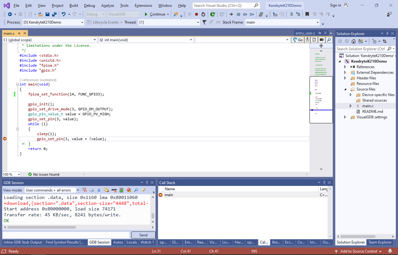
- Remove the breakpoint and press F5 to continue execution. The on-board LED will begin blinking:
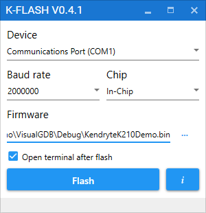
- The Kendryte K210 chip does include any programmable FLASH memory. Instead, it downloads the firmware from the external FLASH memory into its RAM and runs it from there. Debugging a project with VisualGDB will copy the firmware into the RAM, but will not overwrite the external FLASH chip on the MAIX board. In order to program the built project into the FLASH chip, download and run the K-FLASH tool and then point it to the .bin file produced by VisualGDB:
- The original Kendryte fork of OpenOCD does not support debugging both cores of the K210 chip at once (breakpoint hitting on a core that is not currently debugged would cause the firmware to crash). The OpenOCD version shipped with VisualGDB contains a fix for the issue (see our CMake-based fork of the Kendryte’s OpenOCD), however it is still less reliable than the OpenOCD for ARM devices. If you encounter strange behavior with OpenOCD, consider the following techniques to improve reliability:
- Try setting the breakpoints before the program starts instead of adding/removing them while it is running.
- Try reloading the firmware by running the “load” command via the GDB Session window.
- Try programming a simple firmware (e.g. the “Hello, World” sample) into the FLASH memory using the K-FLASH tool and then physically reset the K210 chip and program the regular firmware via OpenOCD.