Creating a Basic Remote Video Monitor with ESP32-WROVER and ESP32-CAM
In this tutorial we will show how to create a basic remote video monitor using 2 ESP32-based boards communicating via Wi-Fi:
- The ESP32-CAM module will be used to capture pictures
- The ESP32-WROVER module will be used to display the captured images
The modules will communicate to each other using Wi-Fi (the WROVER module will act as a Wi-Fi access point and the ESP32-CAM module will connect to it). The diagram below provides an overview of the communication between the modules: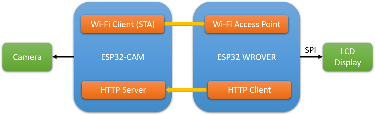 Before you begin, install Visual Studio and VisualGDB 5.4 or later and ensure that you can program both modules by following our ESP32-WROVER LCD tutorial and the ESP32-CAM tutorial.
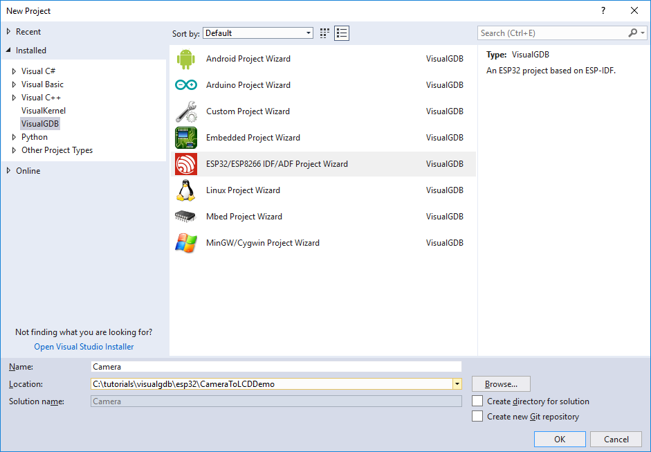
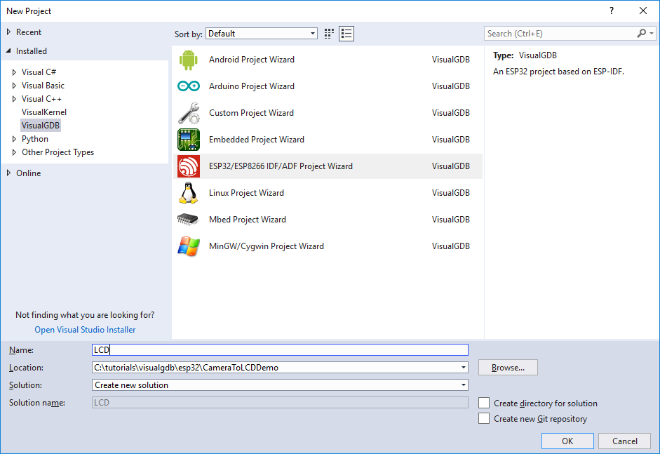
- We will begin with creating the firmware for the camera module. Start Visual Studio and open the VisualGDB ESP32 project wizard:
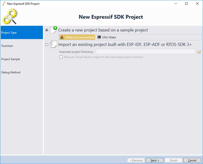
- On the first page of the wizard select the CMake build subsystem:

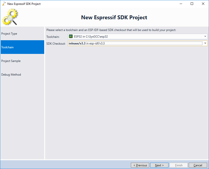
- Next, select the latest ESP32 toolchain and the latest ESP-IDF checkout:
 Update: For better compatibility with the latest ESP32 tools, we recommend selecting the consolidated toolchain instead.
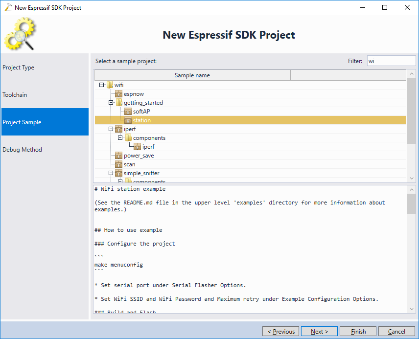
 - We will create the camera firmware by cloning the Wi-Fi station example and modifying it to serve pictures taken from the camera via HTTP. Hence, pick the wifi/getting_started/station sample:
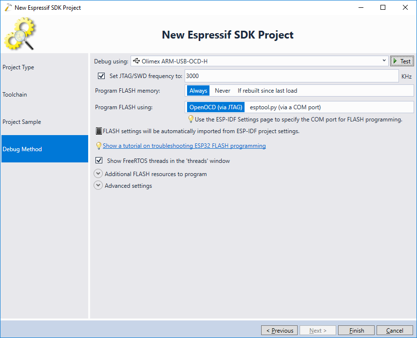
- On the Debug Settings page select the settings necessary to debug the ESP32-CAM module. If you are not sure, follow the ESP32-CAM tutorial to get JTAG to work:
- Press “Finish” to generate the project. Once the project is loaded, right-click on the components view in Solution Explorer and select Add->New Item:

- Add an empty component called “esp32-camera” to the project:

- Now we will replace our dummy component with a copy of the actual ESP32 camera library. Open the Command Prompt window and go to the project directory. Then run the following commands in the terminal:
rmdir /s /q components\esp32-camera
git clone https://github.com/espressif/esp32-camera components/esp32-camera
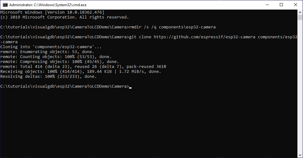 If the git command doesn’t work make sure you have git installed and referenced in the PATH variable.
 - Once the camera library is cloned, go back to Visual Studio and reload the project:

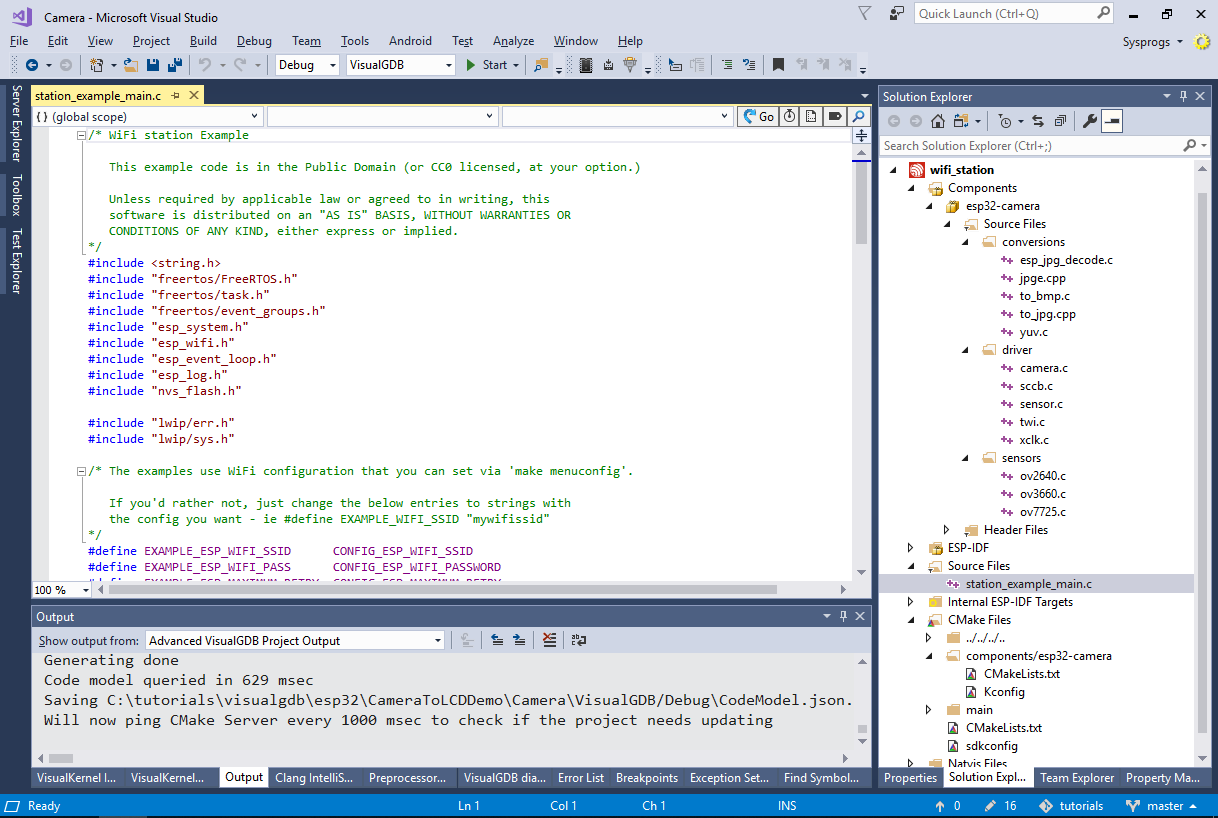
- Once the project is reloaded, VisualGDB will automatically display the contents of the esp32-camera library in Solution Explorer:
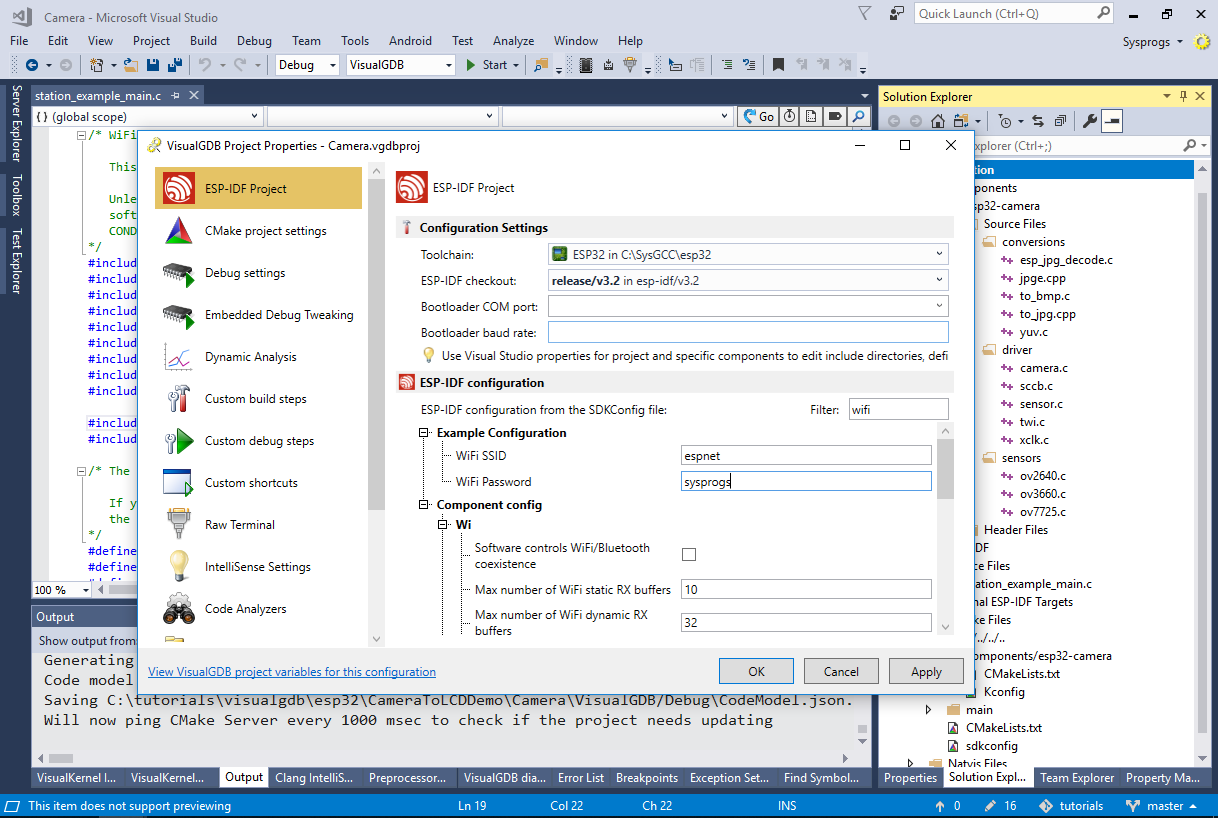
- Before we proceed with using the camera library, open VisualGDB Project Properties and set the Wi-Fi SSID and password to match your Wi-Fi network:
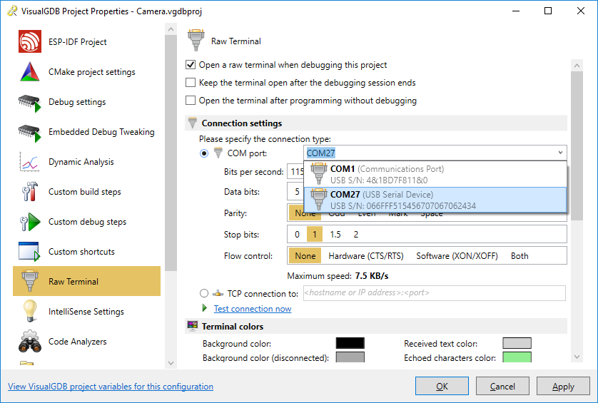
- If you are using the Custom edition of VisualGDB, we recommend enabling the raw terminal on the COM port connected to the ESP32-CAM board. For lower editions, simply use an external terminal program instead:
- Now we will add the code that will take pictures using the camera. First of all, copy the camera I/O pin definitions from the Arduino sample:
#define CAMERA_MODEL_AI_THINKER

#if defined(CAMERA_MODEL_WROVER_KIT)
#define PWDN_GPIO_NUM -1
#define RESET_GPIO_NUM -1
#define XCLK_GPIO_NUM 21
#define SIOD_GPIO_NUM 26
#define SIOC_GPIO_NUM 27

#define Y9_GPIO_NUM 35
#define Y8_GPIO_NUM 34
#define Y7_GPIO_NUM 39
#define Y6_GPIO_NUM 36
#define Y5_GPIO_NUM 19
#define Y4_GPIO_NUM 18
#define Y3_GPIO_NUM 5
#define Y2_GPIO_NUM 4
#define VSYNC_GPIO_NUM 25
#define HREF_GPIO_NUM 23
#define PCLK_GPIO_NUM 22

#elif defined(CAMERA_MODEL_M5STACK_PSRAM)
#define PWDN_GPIO_NUM -1
#define RESET_GPIO_NUM 15
#define XCLK_GPIO_NUM 27
#define SIOD_GPIO_NUM 25
#define SIOC_GPIO_NUM 23

#define Y9_GPIO_NUM 19
#define Y8_GPIO_NUM 36
#define Y7_GPIO_NUM 18
#define Y6_GPIO_NUM 39
#define Y5_GPIO_NUM 5
#define Y4_GPIO_NUM 34
#define Y3_GPIO_NUM 35
#define Y2_GPIO_NUM 32
#define VSYNC_GPIO_NUM 22
#define HREF_GPIO_NUM 26
#define PCLK_GPIO_NUM 21

#elif defined(CAMERA_MODEL_AI_THINKER)
#define PWDN_GPIO_NUM 32
#define RESET_GPIO_NUM -1
#define XCLK_GPIO_NUM 0
#define SIOD_GPIO_NUM 26
#define SIOC_GPIO_NUM 27

#define Y9_GPIO_NUM 35
#define Y8_GPIO_NUM 34
#define Y7_GPIO_NUM 39
#define Y6_GPIO_NUM 36
#define Y5_GPIO_NUM 21
#define Y4_GPIO_NUM 19
#define Y3_GPIO_NUM 18
#define Y2_GPIO_NUM 5
#define VSYNC_GPIO_NUM 25
#define HREF_GPIO_NUM 23
#define PCLK_GPIO_NUM 22

#else
#error "Camera model not selected"
#endif
Then add a basic HTTP request handler that will take a picture and send it via HTTP each time it receives a request:
#include <esp_camera.h>
#include <esp_http_server.h>

httpd_handle_t s_httpd = NULL;

esp_err_t jpg_httpd_handler(httpd_req_t *req)
{
    camera_fb_t *fb = NULL;
    esp_err_t res = ESP_OK;
    size_t fb_len = 0;
    int64_t fr_start = esp_timer_get_time();

    fb = esp_camera_fb_get();
    if (!fb)
    {
        ESP_LOGE(TAG, "Camera capture failed");
        httpd_resp_send_500(req);
        return ESP_FAIL;
    }

    res = httpd_resp_set_type(req, "image/jpeg");

    if (res == ESP_OK)
    {
        fb_len = fb->len;
        res = httpd_resp_send(req, (const char *)fb->buf, fb->len);
    }

    esp_camera_fb_return(fb);
    int64_t fr_end = esp_timer_get_time();
    ESP_LOGI(TAG, "JPG: %uKB %ums", (uint32_t)(fb_len / 1024), (uint32_t)((fr_end - fr_start) / 1000));
    return res;
}
Finally, replace the app_main() function with a version that enables the camera driver and starts an HTTP server:
void app_main()
{
    //Initialize NVS
    esp_err_t ret = nvs_flash_init();
    if (ret == ESP_ERR_NVS_NO_FREE_PAGES || ret == ESP_ERR_NVS_NEW_VERSION_FOUND)
    {
        ESP_ERROR_CHECK(nvs_flash_erase());
        ret = nvs_flash_init();
    }
    ESP_ERROR_CHECK(ret);

    ESP_LOGI(TAG, "ESP_WIFI_MODE_STA");
    wifi_init_sta();

    camera_config_t config;
    config.ledc_channel = LEDC_CHANNEL_0;
    config.ledc_timer = LEDC_TIMER_0;
    config.pin_d0 = Y2_GPIO_NUM;
    config.pin_d1 = Y3_GPIO_NUM;
    config.pin_d2 = Y4_GPIO_NUM;
    config.pin_d3 = Y5_GPIO_NUM;
    config.pin_d4 = Y6_GPIO_NUM;
    config.pin_d5 = Y7_GPIO_NUM;
    config.pin_d6 = Y8_GPIO_NUM;
    config.pin_d7 = Y9_GPIO_NUM;
    config.pin_xclk = XCLK_GPIO_NUM;
    config.pin_pclk = PCLK_GPIO_NUM;
    config.pin_vsync = VSYNC_GPIO_NUM;
    config.pin_href = HREF_GPIO_NUM;
    config.pin_sscb_sda = SIOD_GPIO_NUM;
    config.pin_sscb_scl = SIOC_GPIO_NUM;
    config.pin_pwdn = PWDN_GPIO_NUM;
    config.pin_reset = RESET_GPIO_NUM;
    config.xclk_freq_hz = 20000000;
    config.pixel_format = PIXFORMAT_JPEG;

    config.frame_size = FRAMESIZE_QVGA;
    config.jpeg_quality = 10;
    config.fb_count = 1;

    // camera init
    esp_err_t err = esp_camera_init(&config);
    ESP_ERROR_CHECK(err);

    sensor_t *s = esp_camera_sensor_get();
    s->set_framesize(s, FRAMESIZE_QVGA);
    s->set_quality(s, 20);

    httpd_config_t httpdConfig = HTTPD_DEFAULT_CONFIG();

    httpd_uri_t index_uri = {
        .uri = "/",
        .method = HTTP_GET,
        .handler = jpg_httpd_handler,
        .user_ctx = NULL};

    if (httpd_start(&s_httpd, &httpdConfig) == ESP_OK)
    {
        httpd_register_uri_handler(s_httpd, &index_uri);
    }
}
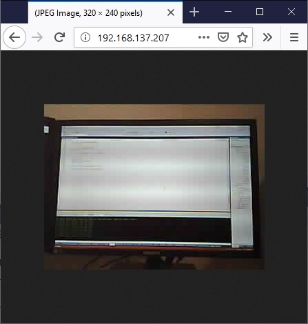
- Press F5 to build and start your program. Take a note of the IP address reported by the board via the COM port:

- Open the IP address of the board in your browser. You will see a low-resolution picture from the camera:
- Now it’s the time to create the firmware for the ESP32-WROVER board that will request the pictures from the camera and display them on the on-board LCD screen. Open another instance of Visual Studio and start the VisualGDB ESP32 project wizard:
- Proceed with the CMake build subsystem:
- This time ensure you are using ESP-IDF 3.3 or later, as the older versions do not report the IP addresses assigned to the Wi-Fi clients:
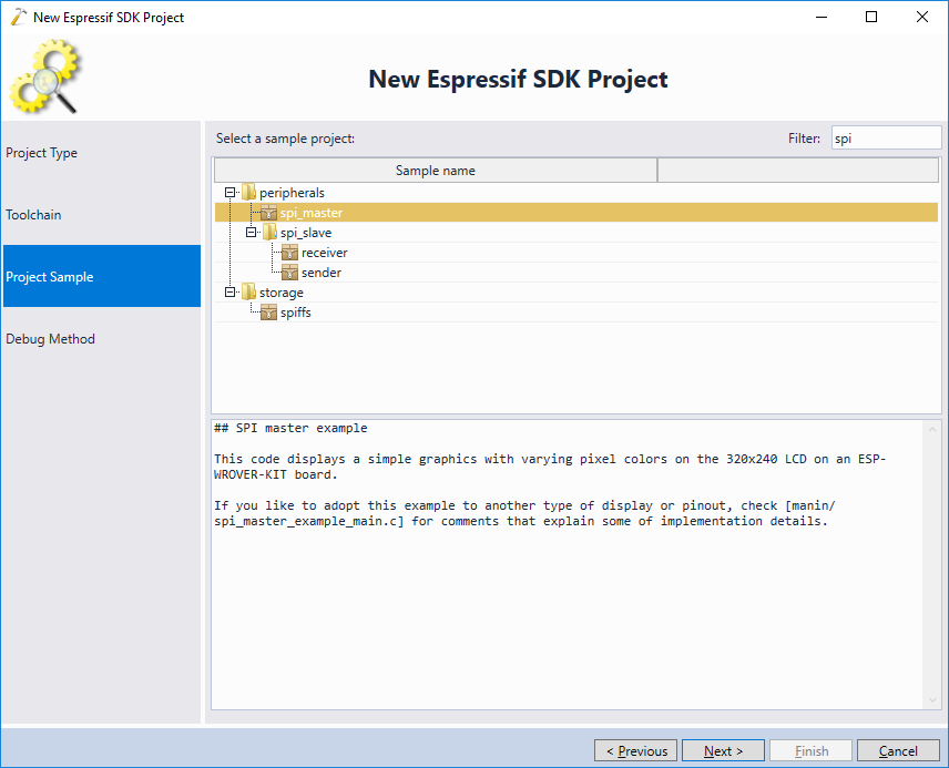
- Select the spi_master sample and press “next”:
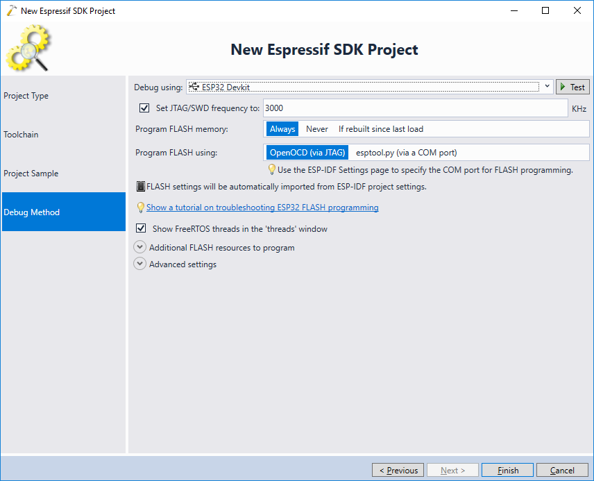
- Select the debug settings for the ESP32-WROVER board. Do not confuse them with the settings for the ESP32-CAM module:
- Now we will modify the LCD display example to show the pictures received via Wi-Fi instead of the hardcoded JPEG image. First of all, modify the decode_image() function to accept an arbitrary JPEG buffer instead of the one in the FLASH memory:
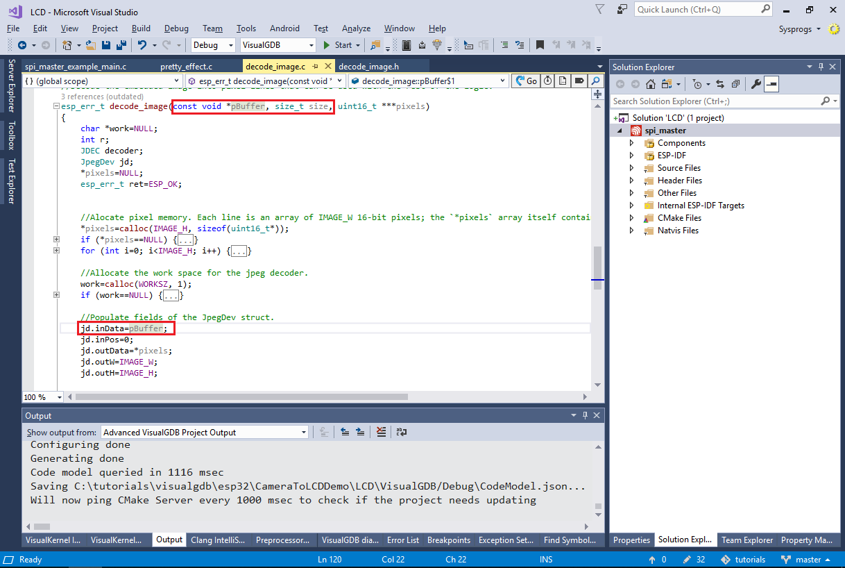 See the ESP32-WROVER LCD tutorial for more details about the roles of various LCD-related functions.
 - Now we will proceed creating a Wi-Fi access point. Add the following code to the main source file:
#include "freertos/FreeRTOS.h"
#include "freertos/task.h"
#include "freertos/event_groups.h"
#include "esp_system.h"
#include "esp_wifi.h"
#include "esp_event_loop.h"
#include "esp_log.h"
#include "nvs_flash.h"
#include "esp_http_client.h"

ip4_addr_t s_ClientIP;
static EventGroupHandle_t s_wifi_event_group;
const int WIFI_CONNECTED_BIT = BIT0;

static esp_err_t event_handler(void *ctx, system_event_t *event)
{
    switch (event->event_id)
    {
    case SYSTEM_EVENT_AP_STAIPASSIGNED:
        s_ClientIP = event->event_info.ap_staipassigned.ip;
        xEventGroupSetBits(s_wifi_event_group, WIFI_CONNECTED_BIT);
        break;
    default:
        break;
    }
    return ESP_OK;
}

#define WIFI_SSID "espnet"
#define WIFI_PASSWORD "sysprogs"

void wifi_init_softap()
{
    s_wifi_event_group = xEventGroupCreate();

    esp_err_t ret = nvs_flash_init();
    if (ret == ESP_ERR_NVS_NO_FREE_PAGES || ret == ESP_ERR_NVS_NEW_VERSION_FOUND)
    {
        ESP_ERROR_CHECK(nvs_flash_erase());
        ret = nvs_flash_init();
    }
    ESP_ERROR_CHECK(ret);

    tcpip_adapter_init();
    ESP_ERROR_CHECK(esp_event_loop_init(event_handler, NULL));

    wifi_init_config_t cfg = WIFI_INIT_CONFIG_DEFAULT();
    ESP_ERROR_CHECK(esp_wifi_init(&cfg));
    wifi_config_t wifi_config = {
        .ap = {
            .ssid = WIFI_SSID,
            .ssid_len = strlen(WIFI_SSID),
            .password = WIFI_PASSWORD,
            .max_connection = 4,
            .authmode = WIFI_AUTH_WPA2_PSK},
    };

    ESP_ERROR_CHECK(esp_wifi_set_mode(WIFI_MODE_AP));
    ESP_ERROR_CHECK(esp_wifi_set_config(ESP_IF_WIFI_AP, &wifi_config));
    ESP_ERROR_CHECK(esp_wifi_start());
}
Ensure that the Wi-Fi SSID and password on the WROVER board match the SSID and password in the ESP32-CAM firmware and do not conflict with your normal Wi-Fi network.
Note how the handler for the SYSTEM_EVENT_AP_STAIPASSIGNED event (raised by ESP-IDF when a client connected to our access point gets assigned an IP address) saves the address assigned to the last client into the s_ClientIP variable.
- Add the following function that will continuously download the JPEG images from the last connected client and will display them on the LCD screen:
#include "decode_image.h"

void GetImagesFromClient(spi_device_handle_t spi)
{
    const int kMaxJpegFileSize = 32768;
    char *pBuf = (char *)malloc(kMaxJpegFileSize);

    uint16_t *pDMABuf = heap_caps_malloc(320 * PARALLEL_LINES * sizeof(uint16_t), MALLOC_CAP_DMA);

    for (;;)
    {
        char url[128];
        sprintf(url, "http://%d.%d.%d.%d/", (s_ClientIP.addr >> 0) & 0xFF,
                (s_ClientIP.addr >> 8) & 0xFF,
                (s_ClientIP.addr >> 16) & 0xFF,
                (s_ClientIP.addr >> 24) & 0xFF);

        esp_http_client_config_t config = {
            .url = url,
        };

        esp_http_client_handle_t client = esp_http_client_init(&config);

        esp_http_client_open(client, 0);
        int content_length = esp_http_client_fetch_headers(client);
        int total_read_len = 0, read_len = 0;
        if (total_read_len < content_length && content_length <= kMaxJpegFileSize)
            read_len = esp_http_client_read(client, pBuf, content_length);

        esp_http_client_close(client);
        esp_http_client_cleanup(client);

        if (read_len)
        {
            uint16_t **decoded = NULL;
            esp_err_t rc = decode_image(pBuf, read_len, &decoded);
            if (!rc)
            {
                for (int y = 0; y < 240; y += PARALLEL_LINES)
                {
                    for (int yo = 0; yo < PARALLEL_LINES; yo++)
                        memcpy(pDMABuf + yo * 320, decoded[y + yo], 320 * sizeof(uint16_t));

                    send_lines(spi, y, pDMABuf);
                    send_line_finish(spi);
                }
            }

            if (decoded != NULL)
            {
                for (int i = 0; i < 256; i++)
                {
                    free((decoded)[i]);
                }
                free(decoded);
            }
        }
    }
}
- Finally, remove the call to the pretty_effect_init() function (and the function itself) and replace the end of app_init() with the following code:
    wifi_init_softap();
    xEventGroupWaitBits(s_wifi_event_group, WIFI_CONNECTED_BIT, pdFALSE, pdFALSE, portMAX_DELAY);
    GetImagesFromClient(spi);

- Now you can build and run the WROVER firmware. Once it starts up, power up the ESP32-CAM board and check the WROVER output for messages regarding the Wi-Fi clients:
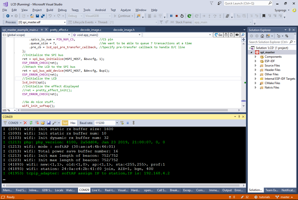 If the boards do not connect, ensure they both use the same Wi-Fi SSID and password and check that it doesn’t conflict with your main Wi-Fi connection.
 - Once the boards connect, you the pictures taken by the camera will be shown on the LCD display of the WROVER module:
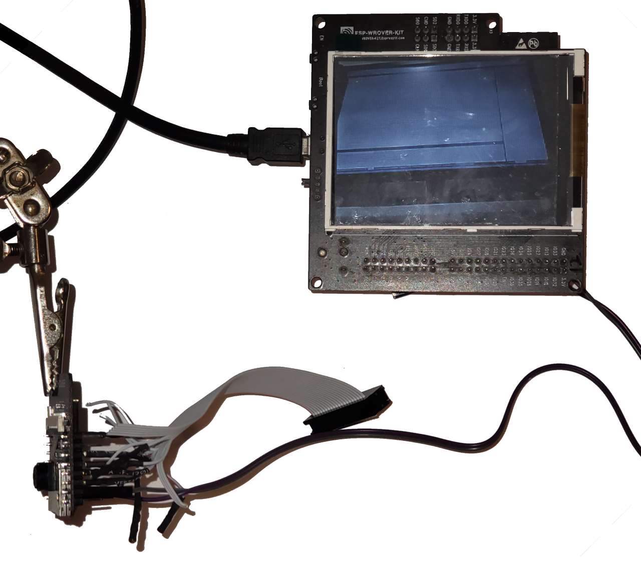
You can find the source code of the projects shown in this tutorial on our GitHub repository. If you would like both boards to connect to your regular Wi-Fi network instead, replace the call to the wifi_init_softap() function in the WROVER firmware by an equivalent of the wifi_init_sta() function from the ESP32-CAM firmware and update the WROVER firmware to fetch the images from a fixed IP address.