Creating an embedded bootloader with VisualGDB
This tutorial shows how to create an embedded bootloader that will be stored in a dedicated region of the FLASH memory and will call the main application after doing some initial processing. The diagram below illustrates the FLASH memory layout that will be produced: The first 16K of memory (0x4000 bytes) will be used by the bootloader, while the reset will be used by the application. The RAM will be reused – once the bootloader exits, the application will reuse the entire RAM to store its variables and stack. We will demonstrate it based on the STM32F4Discovery board, however the techniques shown here will also work for any other barebone embedded platform.
Warning: this tutorial features a deprecated GNU Make-based build system. For more integrated development experience, please consider following bootloader tutorials for Advanced CMake or MSBuild.
Before you begin, install Visual Studio and VisualGDB.
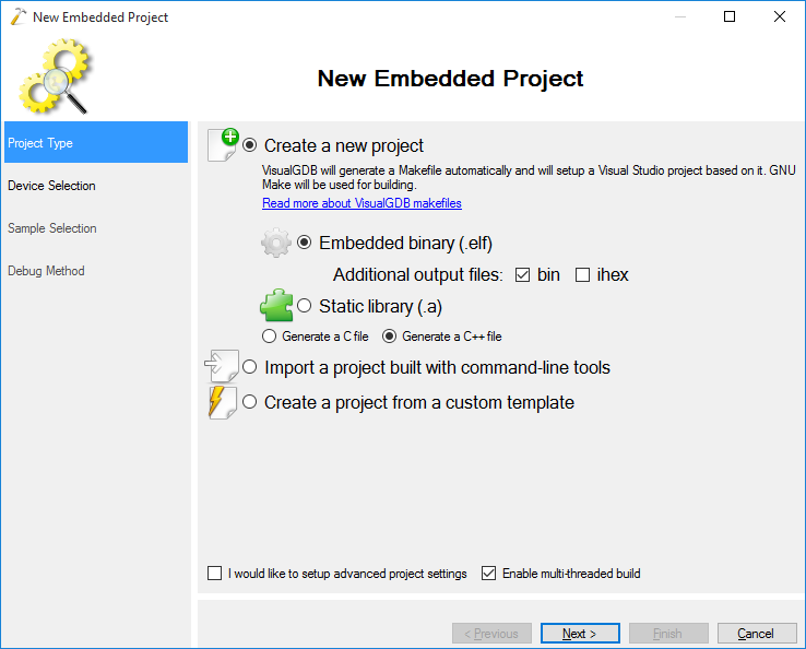
- Start Visual Studio and open the VisualGDB Embedded Project Wizard:
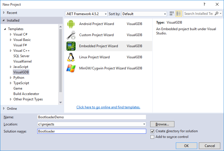 As we will be creating 2 separate projects for the bootloader and for the main application, check the “Create directory for solution” checkbox.
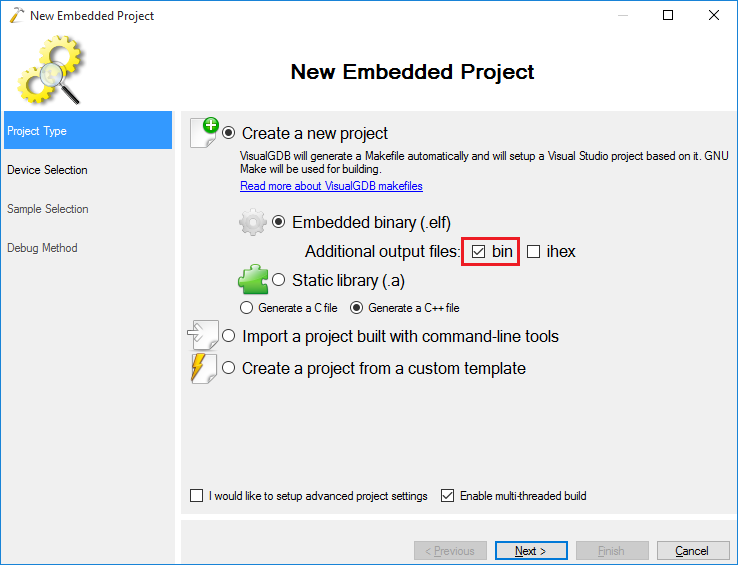
 - Proceed with the default “Create a new project -> Embedded Binary” selection. Ensure that the “bin” file generation is enabled:
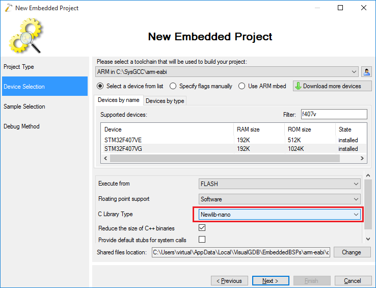
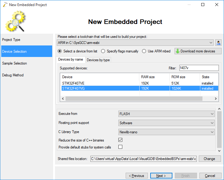
- Select the toolchain and device you are using. In this example we will use the STM32F4Discovery board, however the technique described here will work for any other barebone embedded device:
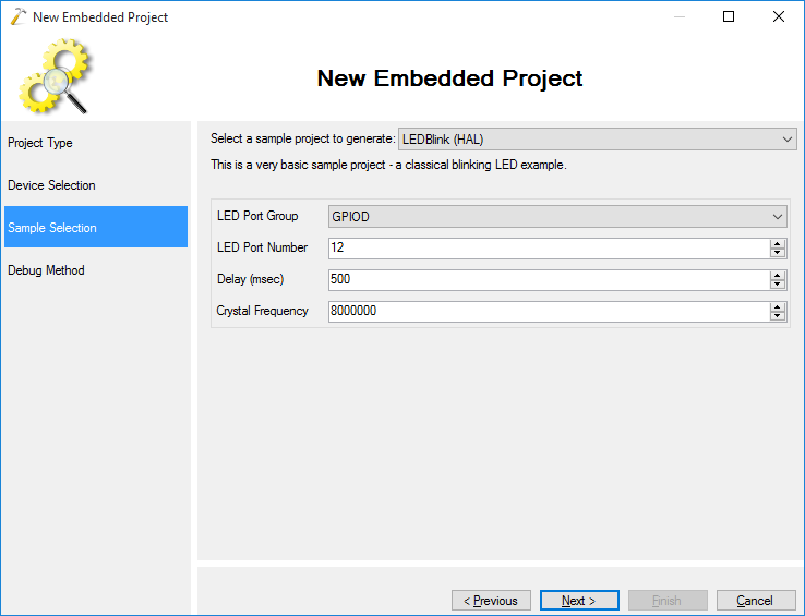
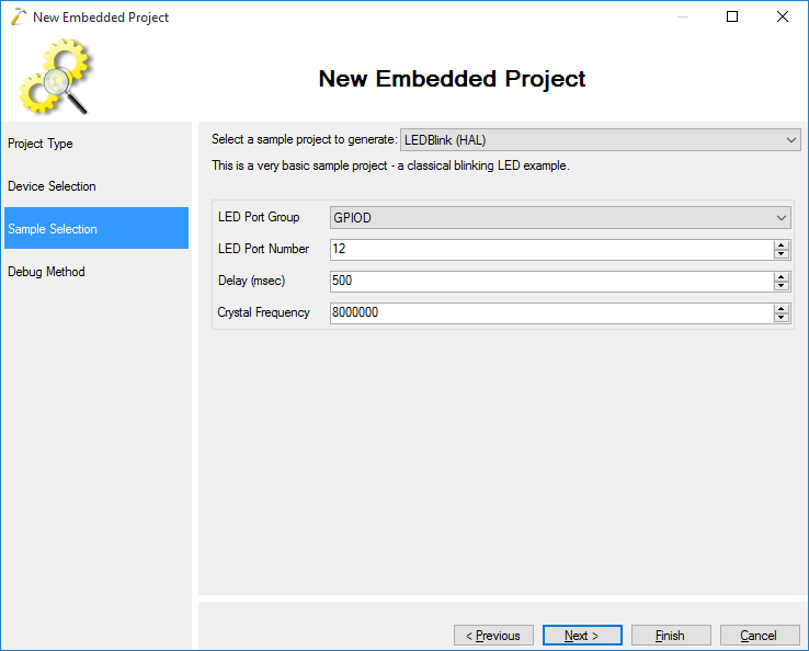
- Select the sample project you want to use. Our demo bootloader will simply blink the LEDs a few times before running the actual application, so we select “LEDBlink” here:
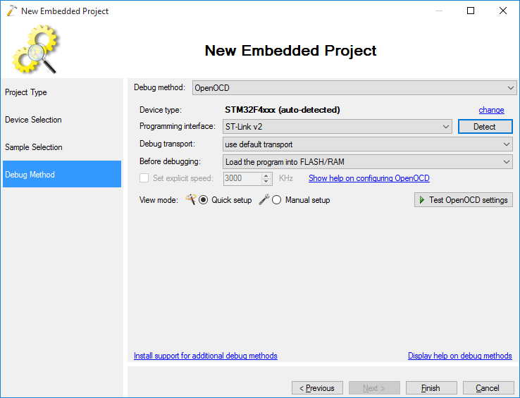
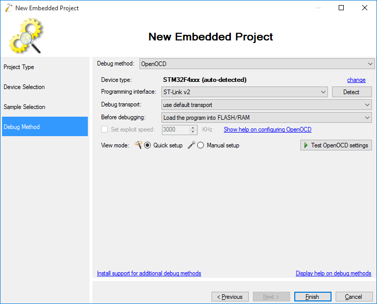
- On the next page select the debugging settings that work with your board. In this example we will use OpenOCD with the ST-Link v2 interface:
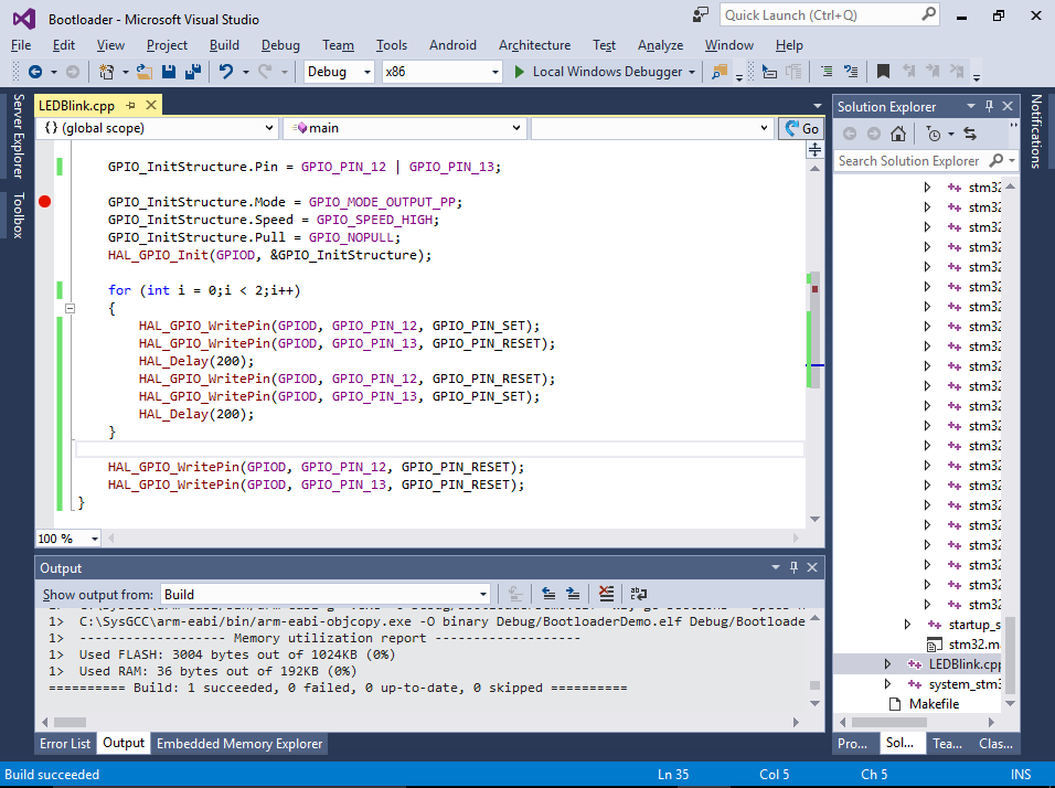
- Press “Finish” to create the project. Then modify the main() function to blink 2 LEDs for 2 times and continue:
int main(void)
{
    HAL_Init();

    __GPIOD_CLK_ENABLE();
    GPIO_InitTypeDef GPIO_InitStructure;

    GPIO_InitStructure.Pin = GPIO_PIN_12 | GPIO_PIN_13;

    GPIO_InitStructure.Mode = GPIO_MODE_OUTPUT_PP;
    GPIO_InitStructure.Speed = GPIO_SPEED_HIGH;
    GPIO_InitStructure.Pull = GPIO_NOPULL;
    HAL_GPIO_Init(GPIOD, &GPIO_InitStructure);

    for (int i = 0;i < 2;i++)
    {
        HAL_GPIO_WritePin(GPIOD, GPIO_PIN_12, GPIO_PIN_SET);
        HAL_GPIO_WritePin(GPIOD, GPIO_PIN_13, GPIO_PIN_RESET);
        HAL_Delay(200);
        HAL_GPIO_WritePin(GPIOD, GPIO_PIN_12, GPIO_PIN_RESET);
        HAL_GPIO_WritePin(GPIOD, GPIO_PIN_13, GPIO_PIN_SET);
        HAL_Delay(200);
    }

    HAL_GPIO_WritePin(GPIOD, GPIO_PIN_12, GPIO_PIN_RESET);
    HAL_GPIO_WritePin(GPIOD, GPIO_PIN_13, GPIO_PIN_RESET);
}
Then build the project by pressing Ctrl-Shift-B:
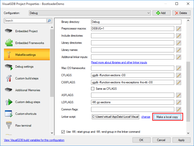
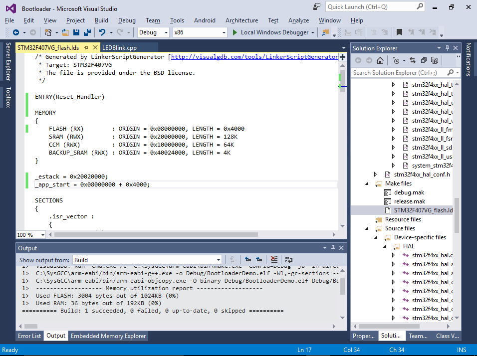
- Now we will edit the linker script to limit the bootloader to the first 16KB of the FLASH and to expect the actual application exactly 16KB after the start of FLASH. Open VisualGDB Project Properties, go to the Makefile Settings page, find the Linker Script option and click the “Make a local copy” button:
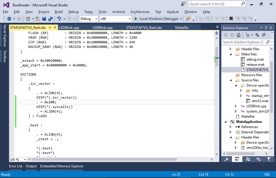
- Open the linker script and limit the size of the FLASH memory to 16K (0x4000). Then define a symbol called _app_start at offset 0x4000 from the beginning of the FLASH memory. Verify that you can still build the project.
- Finally insert the following code to the end of the main() function:
    extern void *_app_start[];
    ((void(*)())_app_start[1])();
On ARM Cortex devices all applications usually start with the interrupt vector table where the first entry contains the initial stack address and the second entry contains the entry point (handler for the Reset interrupt). The code above reads the value of the entry point and calls it like a normal C function.
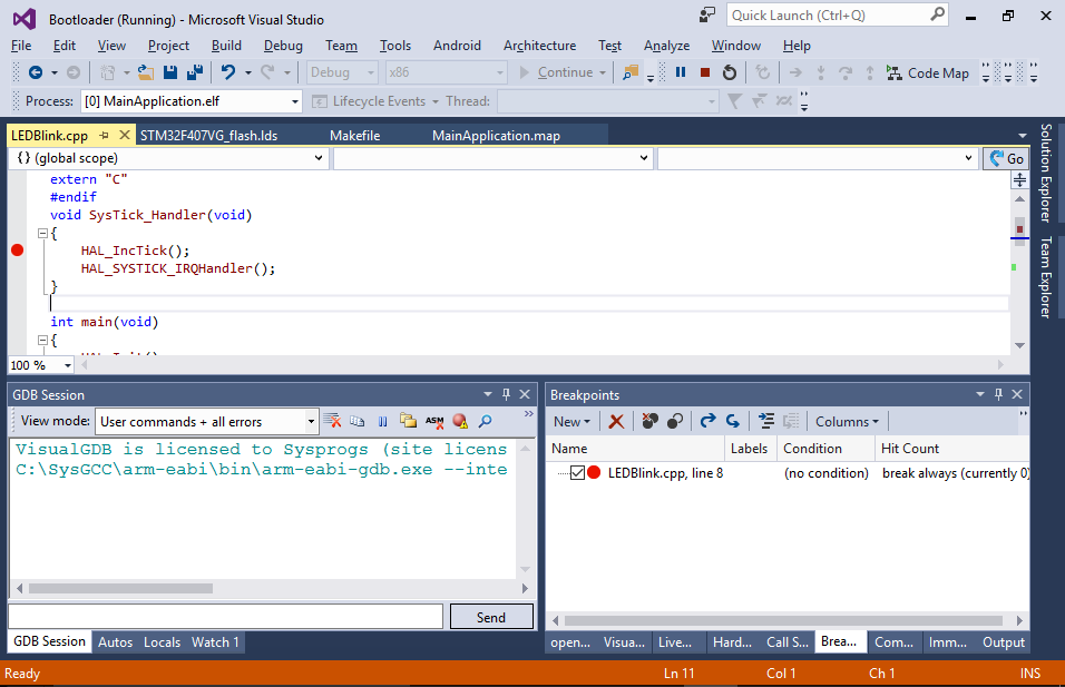
You can try debugging the bootloader to verify that _app_start is defined at offset 0x4000 from the start of FLASH, however the call will actually hang your program as no actual application is present after the bootloader: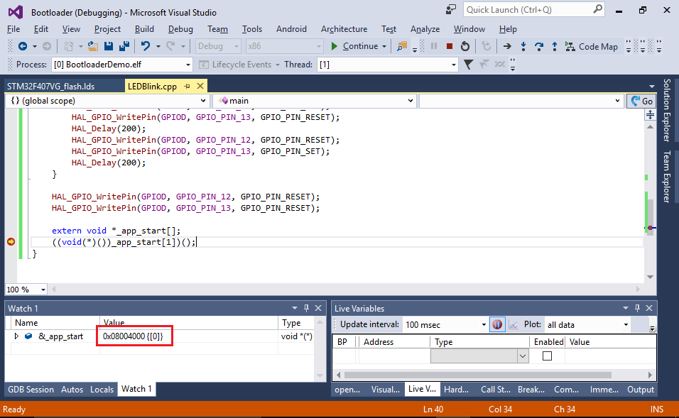
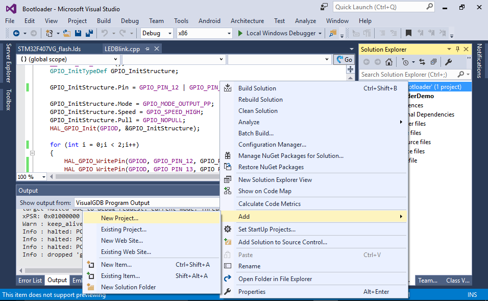
- Now we will create another project and embed our bootloader into it. Right-click inside Solution Explorer and select “Add->New Project”:
- Select the VisualGDB Embedded Project Wizard again:
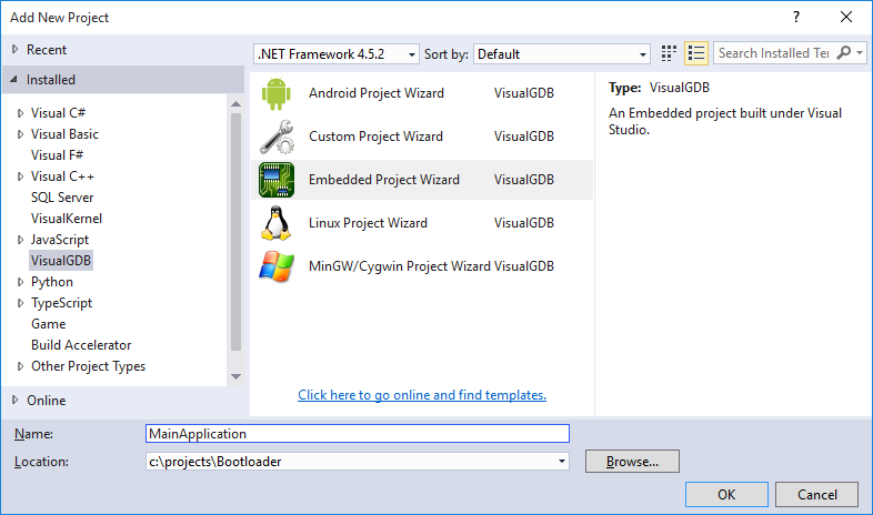
- Make the same choices in the wizard as you did when creating the bootloader. First select “Embedded Binary”:
- Then choose the toolchain and the same device:
- Then pick a sample. The bootloader and the application can be based on completely different samples and can even be based on different types of the libraries (e.g. HAL vs StdPeriph), as they will be linked completely independently. In this example we will select the same LEDBlink sample for simplicity:
- Finally select the debugging settings that work with your board:
- Click “Finish” to create the project and open its Makefile (don’t confuse it with the bootloader’s Makefile). Replace the rule inside the “ifeq ($(TARGETTYPE),APP)” block with the following text:
$(BINARYDIR)/bootldr.o: ../BootloaderDemo/$(CONFIG)/BootloaderDemo.bin
    $(TOOLCHAIN_ROOT)/bin/arm-none-eabi-ld -r -b binary $< -o $@
    $(OBJCOPY) --rename-section .data=.bootldr $@

$(BINARYDIR)/$(TARGETNAME): $(all_objs) $(EXTERNAL_LIBS) $(BINARYDIR)/bootldr.o
    $(LD) -o $@ $(LDFLAGS) $(START_GROUP) $(all_objs) $(LIBRARY_LDFLAGS) $(BINARYDIR)/bootldr.o $(END_GROUP)
Ensure the command lines above start with tabs and not spaces.
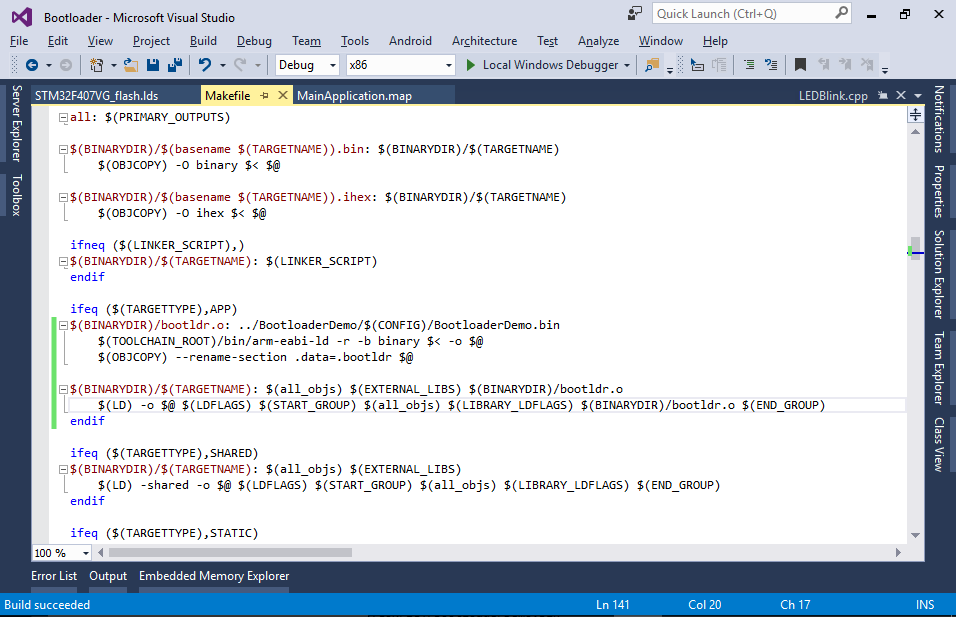 This will convert the binary file from the bootloader project into an object file containing a section called “.bootldr” and add this file to the list of inputs for the application binary.
 - Now we need to modify the application’s linker script to place the “.bootldr” section at the beginning of the FLASH and put the actual application at offset 0x4000. Make a copy of the application’s linker script via VisualGDB Project Properties:
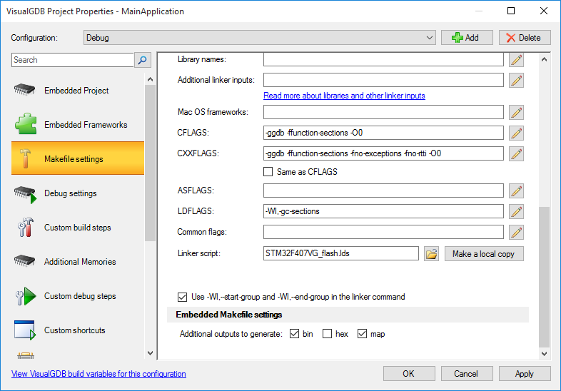 Also enable the generation of the map file in the “Embedded Makefile Settings” section below.
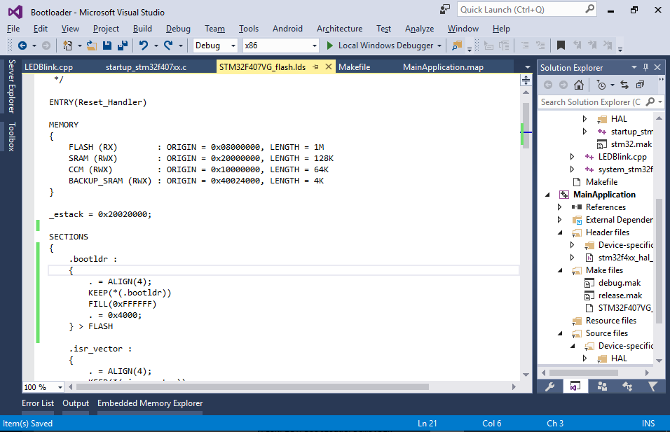
 - Open the linker script and insert the following section definition just before the .isr_vector section:
    .bootldr :
    {
        . = ALIGN(4);
        KEEP(*(.bootldr))
        FILL(0xFFFFFF)
        . = 0x4000;
    } > FLASH
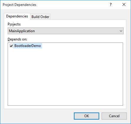
- Finally right-click on the MainApplication project, select Build Dependencies->Project Dependencies and add a dependency to the bootloader project:
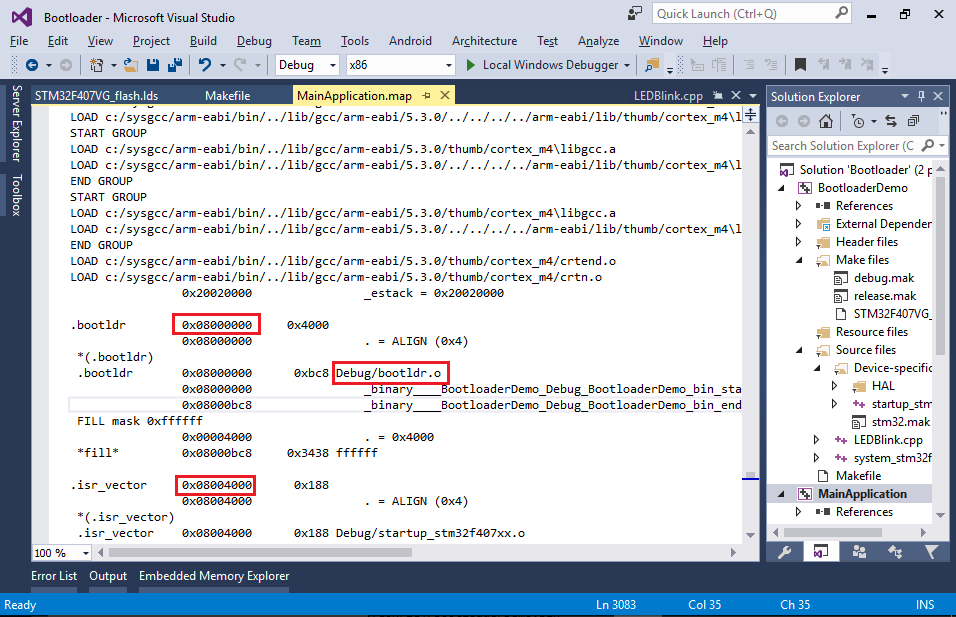
- Now you can build your solution by pressing Ctrl-Shift-B. Once the build is complete, examine the map file in the <Main application>\Debug directory (if there is no .map file, enable it via VisualGDB Project Properties -> Makefile Settings). Verify that the .bootldr section containing the Debug/bootldr.o file got placed at the beginning of the FLASH and that the .isr_vector is actually located at offset 0x4000:
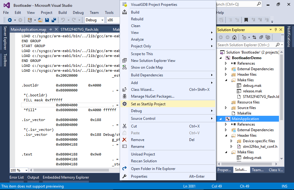
- Set the application project as the startup project so that it gets launched when you press F5:
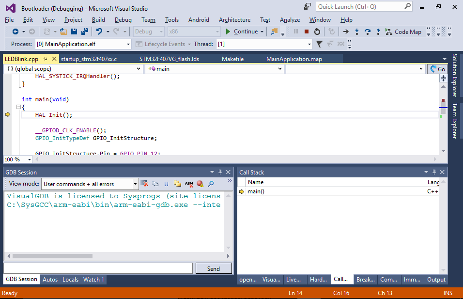
- If you try debugging your project now, you will see that despite being placed in the correct location, the bootloader gets bypassed and the application starts executing directly:
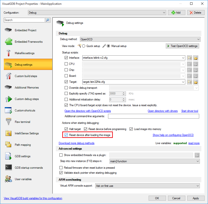
- This happens because GDB reads the entry point from the ELF file and passes control there explicitly. You can override this by opening OpenOCD settings, switching to the manual setup mode and checking the “Reset device after loading the image” checkbox:
- If you start debugging now by pressing F5, you will see how the 2 LEDs quickly blink twice and then the main application takes control and one of the LEDs starts blinking slowly. However, if you examine the application closer, you will notice that the interrupt handlers are not being invoked. This happens because the interrupt vector register still points at the bootloader’s interrupt table, invoking the bootloader’s interrupts. If the bootloader and the application have different memory layouts, this will immediately result in memory corruption!
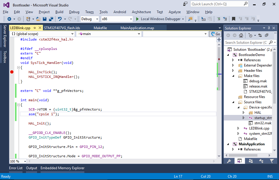
- This can be fixed by setting the SCB->VTOR register to the address of the g_pfnVectors variable from main(). To avoid memory corruption before this line takes effect, we will disable the interrupts in the bootloader (see next step) and enable them from the application via the “cpsie i” instruction:
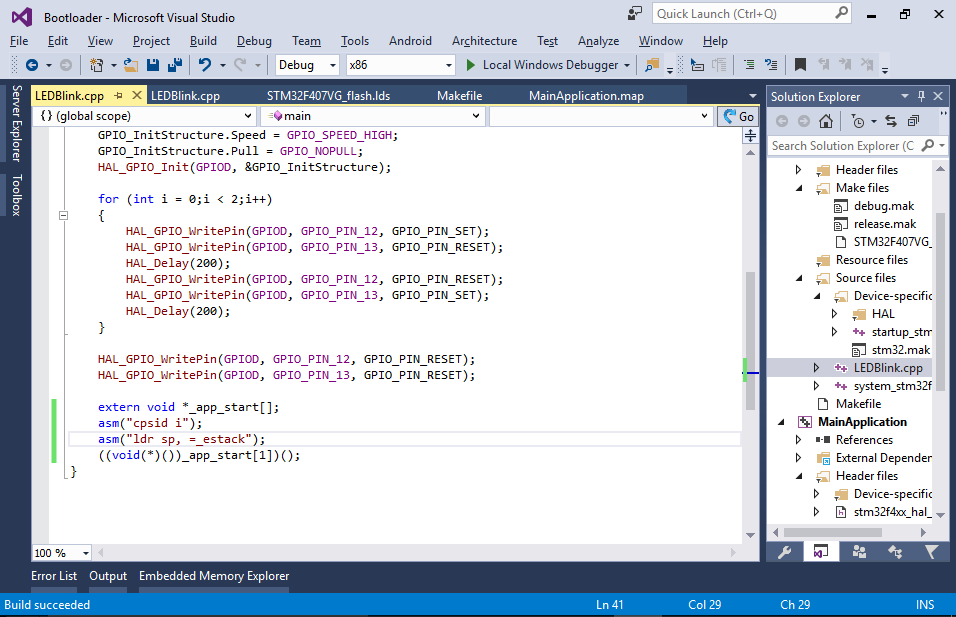
- Modify the bootloader to disable interrupts before calling the application. You can also add code for resetting the stack pointer before that call in order to reuse the stack space that was used by the bootloader:
 Note that on some devices (e.g. LPC1549) you will also need to switch to the internal clock before calling the application, as the vendor-supplied initialization code may not expect any other clock to be active.
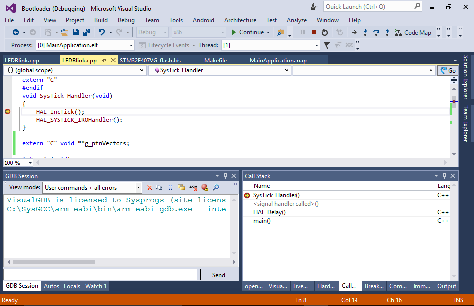
 - Now you can build your project and verify that the interrupt handlers get invoked properly:
 The rest of the tutorial will show some advanced techniques that can be useful when developing bootloaders.
System calls
We will now define a system call table that will allow the application to call a given set of functions from the bootloader without knowing their exact addresses.
- Open the main source file of the bootloader and add the following code there:
int sum(int a, int b)
{
    return a + b;
}

void *g_Syscalls[] __attribute__((section(".syscalls"))) = { (void *)sum };
 This defines a syscall table storing the address of the sum() function. As the application won’t know the address of the sum() function, it will read it from the syscall table that will be placed at a fixed address.
 - To place the syscall table at offset 0x200 from the start of the ISR vector by modifying the .isr_vector section definition in the bootloader’s linker script as follows:
    .isr_vector :
    {
        . = ALIGN(4);
        KEEP(*(.isr_vector))
        . = 0x200;
        KEEP(*(.syscalls))
        . = ALIGN(4);
    } > FLASH
 If your interrupt vector table is longer than 0x200 bytes, the linker will report an overflow, so you can replace 0x200 with a bigger value.
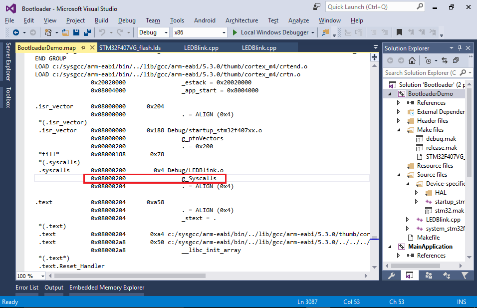
 - Use the bootloader’s map file to verify that the syscall table got placed at the expected address:
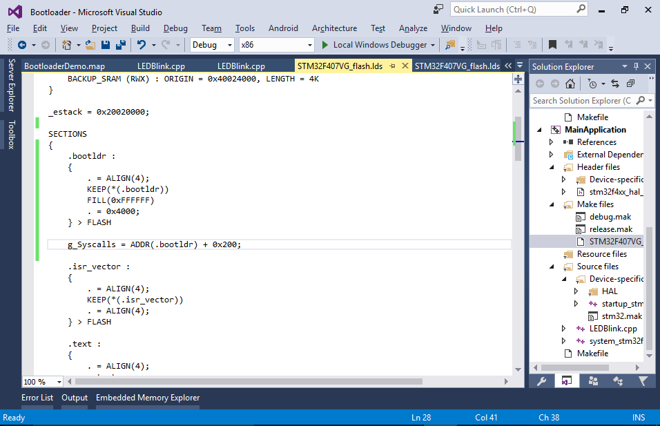
- Now you can define the address of the syscall table in the application’s linker script:
g_Syscalls = ADDR(.bootldr) + 0x200;
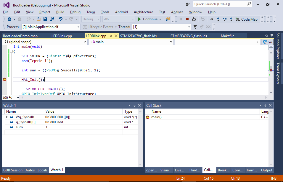
- Now you can invoke the first syscall from the application’s main() function:
extern "C" void **g_pfnVectors;
extern "C" void *g_Syscalls[];

typedef int(*PSUM)(int, int);

int main(void)
{
    //...
    int sum = ((PSUM)g_Syscalls[0])(1, 2);
    //...
}
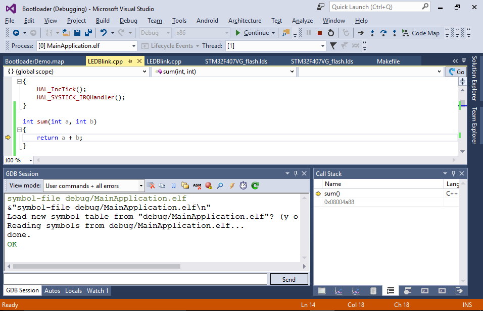
You can now use the debugger to verify that calling sum(1, 2) actually returns 3:
- The only limitation of this approach is that you won’t be able to step into the bootloader’s syscalls as the bootloader symbols cannot be loaded simultaneously with the application symbols. You can however manually switch the loaded symbols by running the “symbol-file <path to the bootloader’s ELF file>” command:
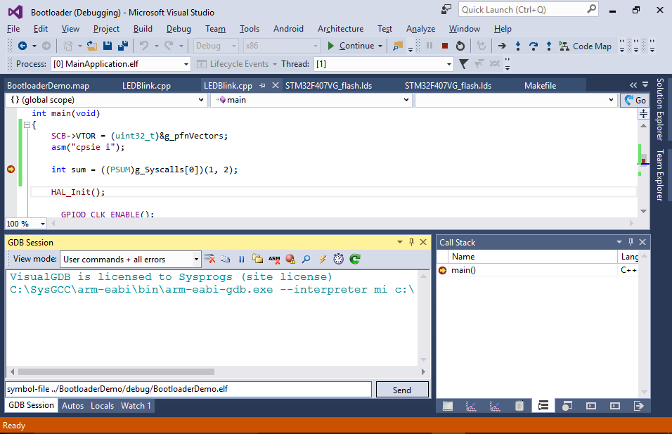
- This will unload the symbols for the application, but load the ones for the bootloader allowing you to set a breakpoint inside sum(). Once the breakpoint hits, you can switch back to the application’s symbols by running the symbol-file command again: