Debugging Raspberry Pi Pico via SWD
This page explains how to prepare the Raspberry Pi Pico for debugging via SWD. Note that the on-board FLASH memory can be programmed via the bootloader and does not require SWD wiring. The steps shown on this page are only needed if you would like to set breakpoints in the code and step through it in a debugger.
General Setup
The Raspberry Pi Pico board has the SWD pins conveniently available on one side, however in order to keep the board compact, they are not following the standard JTAG20 pinout. In order to debug the board using a regular SWD debugger, please connect the pins as shown below:
| Pin name on board | JTAG/SWD signal name | Pin on JTAG20 cable |
| SWDIO | TMS/SWDIO | 7 |
| GND | GND | 2, 4, 6 or 8 |
| SWCLK | TCK/SWCLK | 9 |
| VDD (optional) | +3.3V | 1 |
Connecting the VDD (+3.3V) to pin 1 of the JTAG2o connector will prevent the “No target power” error with some SWD adapters, but is generally optional.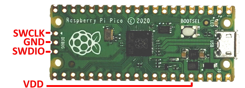 The connection for the Raspberry Pi Pico W board is practically identical:
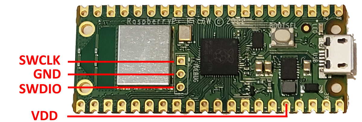
The final setup involving the Raspberry Pi Pico and a JTAG/SWD adapter should look as shown below: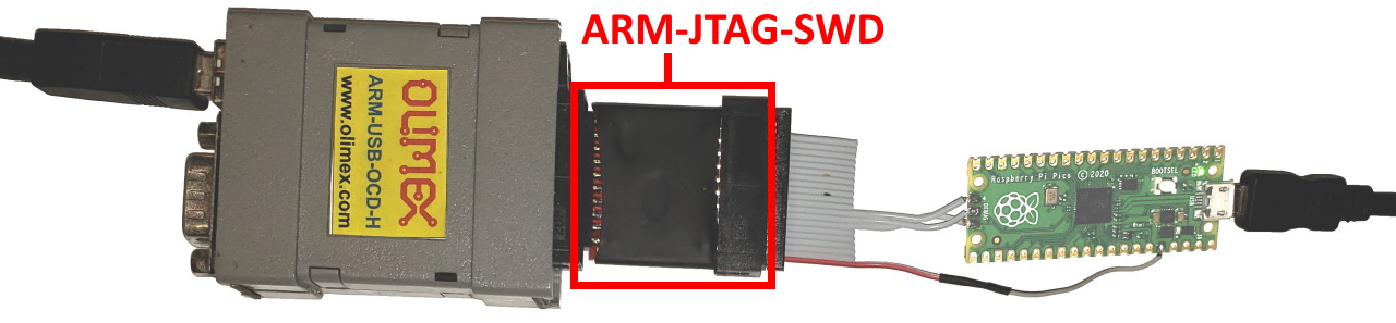 We have tested the following SWD adapters with Raspberry Pi Pico using this setup:
- Segger J-Link
- Olimex ARM-USB-OCD-H (requires ARM-JTAG-SWD module)
- Raspberry Pi 4 (see below)
If you are using a different SWD adapter based on the FT2232 chip (e.g. Flyswatter 2), it will likely work as well, as long as it supports SWD.
WARNING: The RP2040 chip used by Raspberry Pi Pico requires a special OpenOCD fork. VisualGDB will automatically use it when debugging Raspberry Pi Pico. If you are running OpenOCD manually, you can download it here (use openocd_rpi2040.exe instead of openocd.exe).
Debugging with Regular Raspberry Pi
You can use the regular Raspberry Pi board to debug Raspberry Pi Pico (or any other device that supports the SWD transport). In order to do that, connect the following signals on the Raspberry Pi:
| Raspberry Pi Signal | Raspberry Pi Pin Number | JTAG/SWD signal | JTAG20 Pin |
| GPIO24 | 18 | TMS/SWDIO | 7 |
| GPIO25 | 22 | TCK/SWCLK | 9 |
| GND | 20 | GND | 2, 4, 6 or 8 |
The final setup using the modular JTAG20 connector is shown below: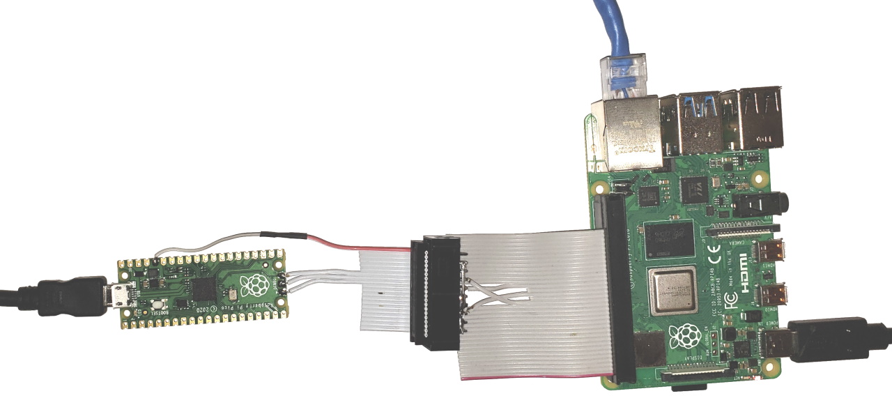 Once the signals have been connected, simply run OpenOCD on Raspberry Pi itself using the interface/raspberrypi-swd.cfg script in order to debug your target. If you are using VisualGDB Linux Edition or higher, simply select “Debug using: OpenOCD (run remotely)” and VisualGDB will automatically build and launch the correct OpenOCD fork on your Raspberry Pi:
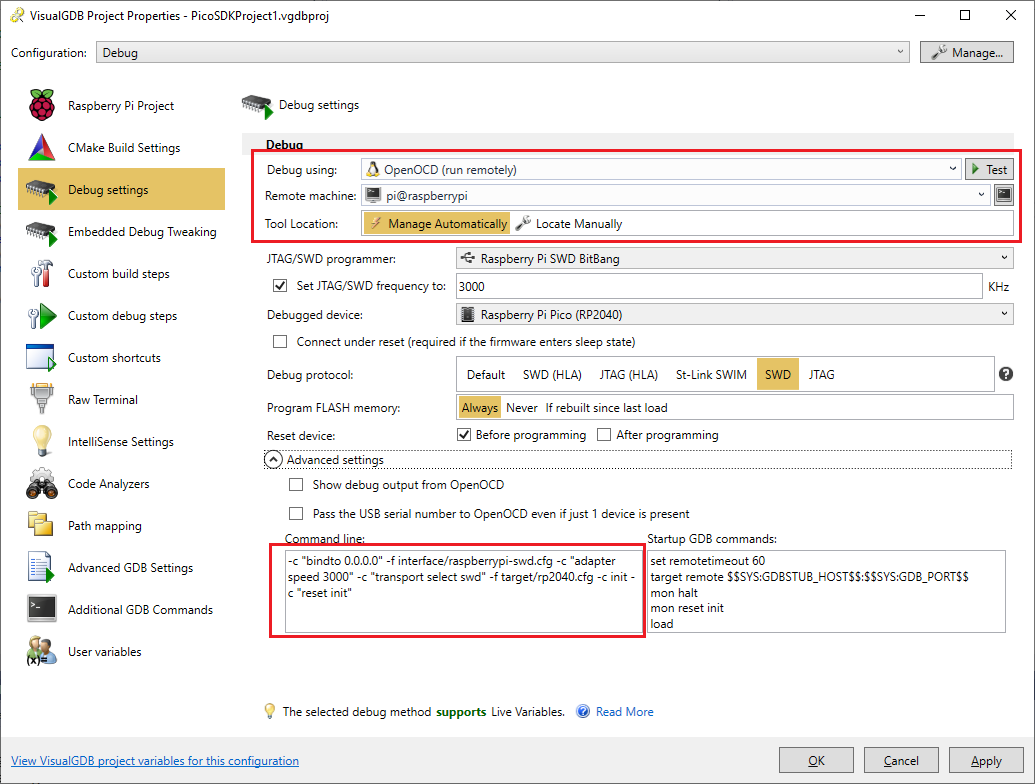 See this tutorial for detailed step-by-step instructions on building and debugging a Raspberry Pi project with Visual Studio and VisualGDB.