Developing Arduino code for STM32 boards with Visual Studio
This tutorial shows how to develop Arduino-based projects for the STM32 boards using the STM32Duino project, Visual Studio and VisualGDB.
We will import the STM32 Arduino cores into VisualGDB and will show how to create and debug a basic project for the STM32F4Discovery board, and also how to programmatically print text into a virtual USB-based COM port provided by the STM32 Arduino framework.
Before you begin, install VisualGDB 5.4R7 or later.
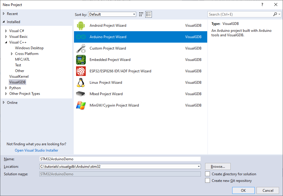
- Start Visual Studio and open the VisualGDB Arduino Project Wizard:
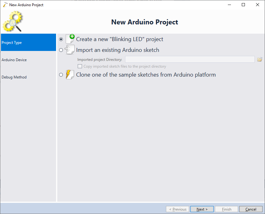
- On the first page of the wizard select Create a new “Blinking LED” project:
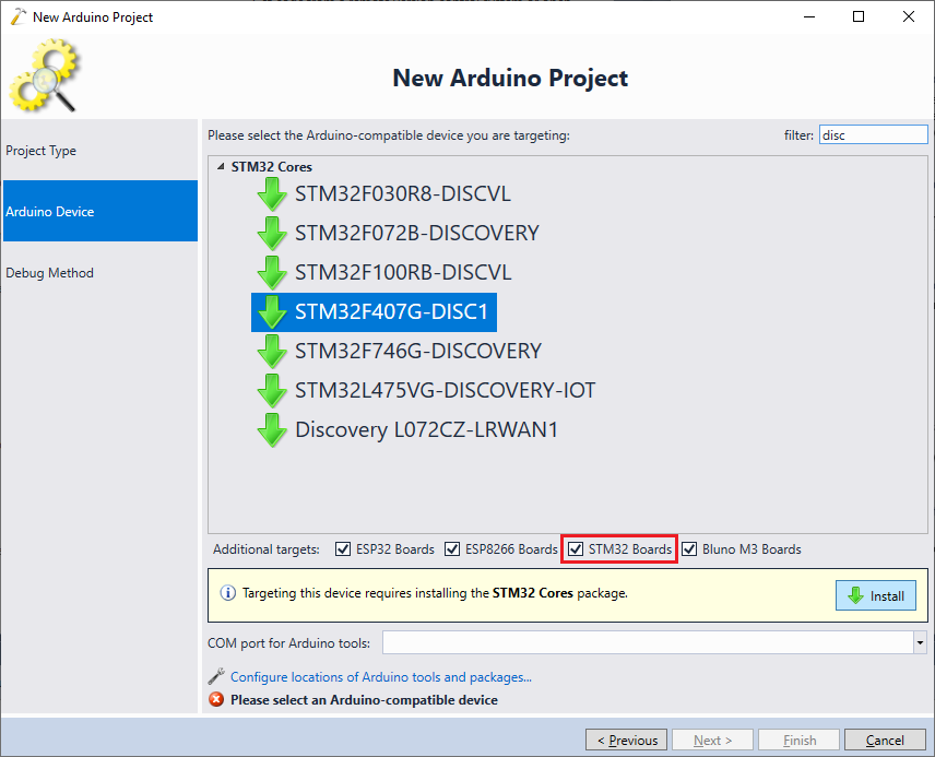
- If you don’t have the STM32 Arduino cores installed, select your board on the next page and click “Install”. If the board is not shown, ensure you have STM32 Boards checkbox enabled:
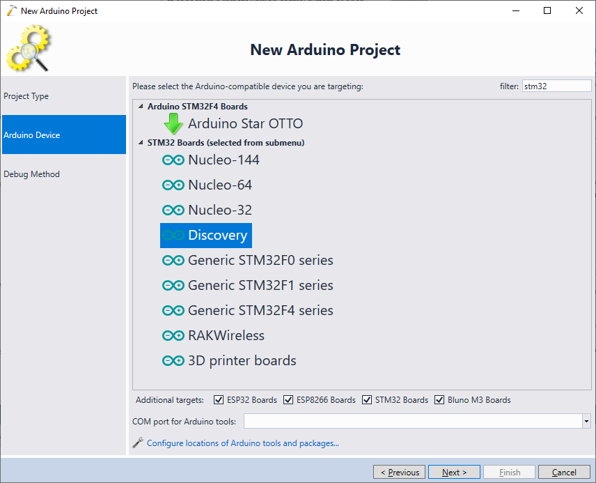
- Once the STM32 Arduino targets are installed, the target list will look differently: instead of listing all boards, the STM32 Arduino package lists board types and lets you specify an exact board via project properties. In this tutorial we are targeting the STM32F4Discovery board, so select Discovery and press “Next”:
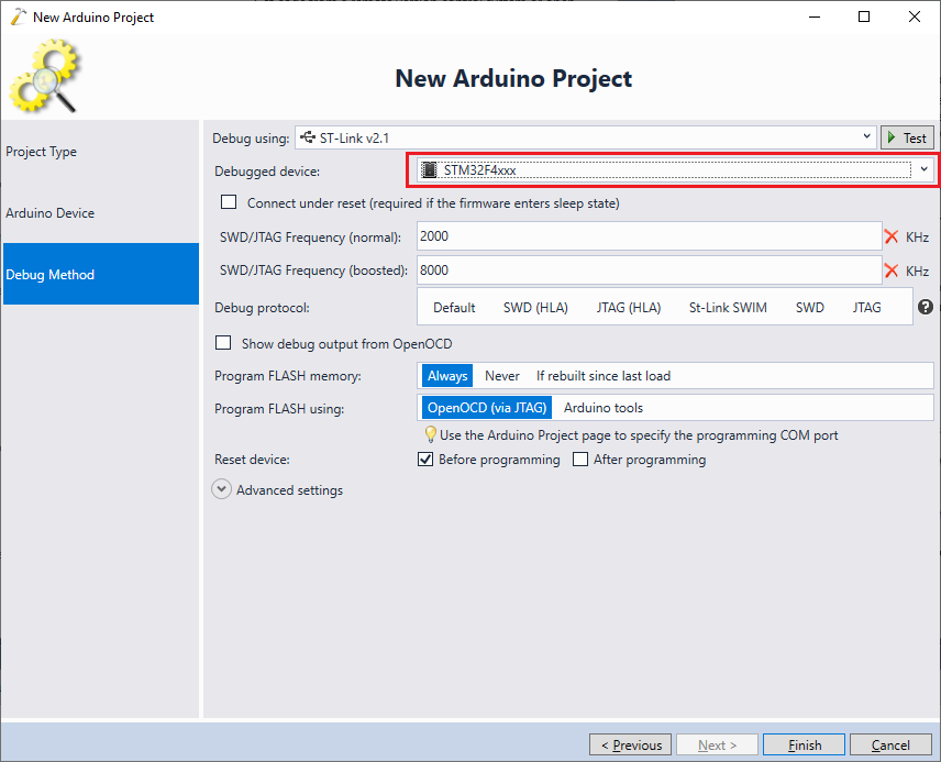
- Connect your board to the USB port and let VisualGDB detect the ST-Link you are using. As the exact board type is not chosen yet, VisualGDB will not automatically detect the debugged device type. Select it manually to match the board type you are using:
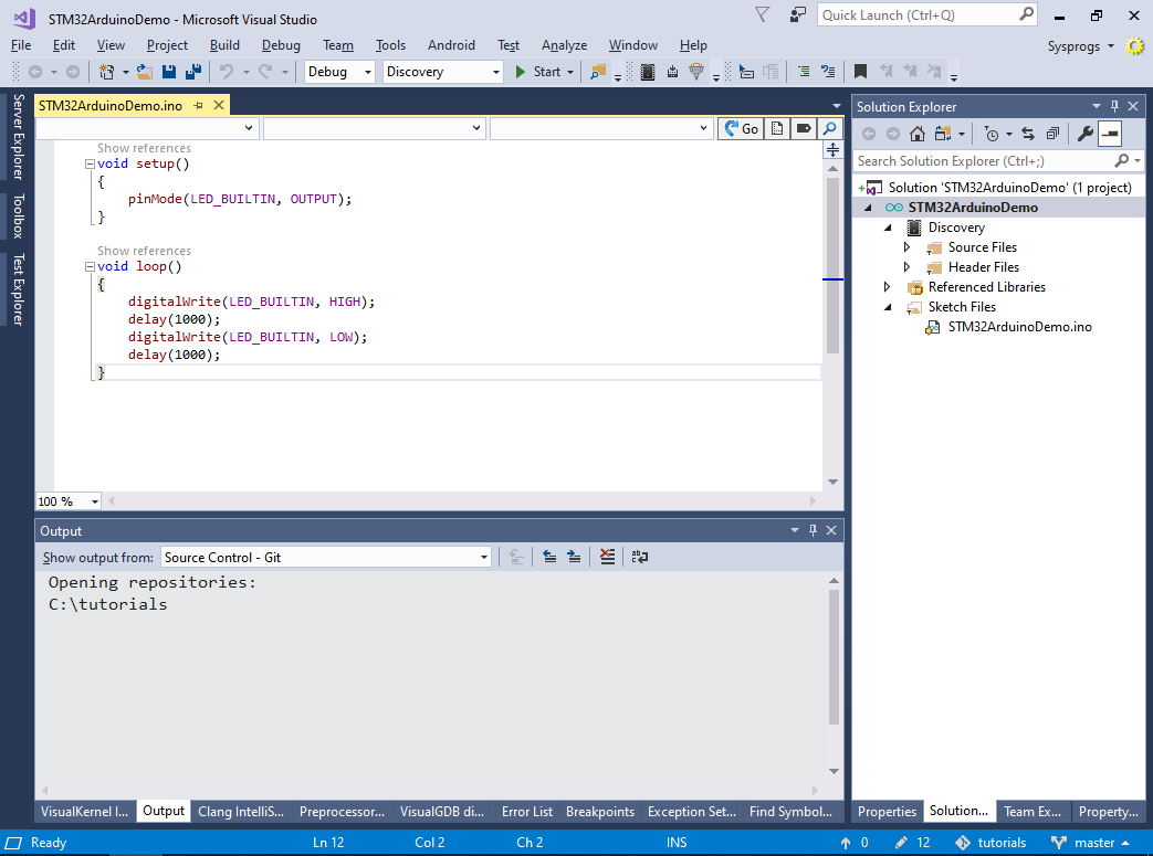
- Press “Finish” to create the project. VisualGDB will generate a basic “Blinking LED” project and will query its structure from Arduino:
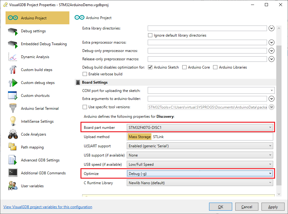
- Right-click on the project in Solution Explorer and select VisualGDB Project Properties. Then pick the exact board you are using and switch the “Optimize” setting to “Debug (-g)” to allow stepping through the code:
 Note that the debug settings chosen in the wizard will override the Arduino-level Upload method setting and hence there is no need to change it.
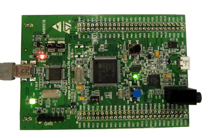
 - Press F5 to build the project and start debugging it. Note how the on-board LED begins blinking:
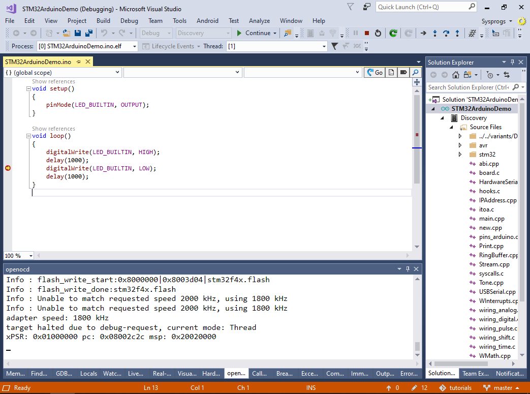
- Set a breakpoint in the loop() function and wait for it to trigger. Once the breakpoint triggers, you will be able to step through the code, view variables and use other debugging functionality:
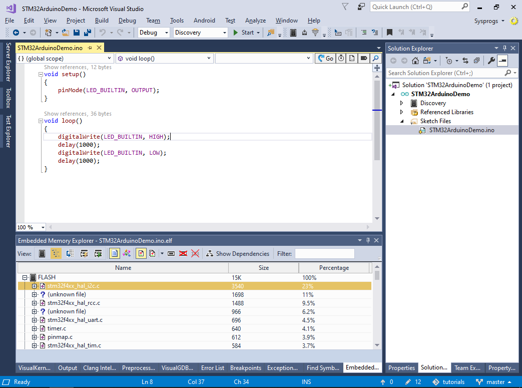
- Use can use the View->Embedded Memory Explorer command to display a detailed report about the memory utilization by the built project and compare different builds:
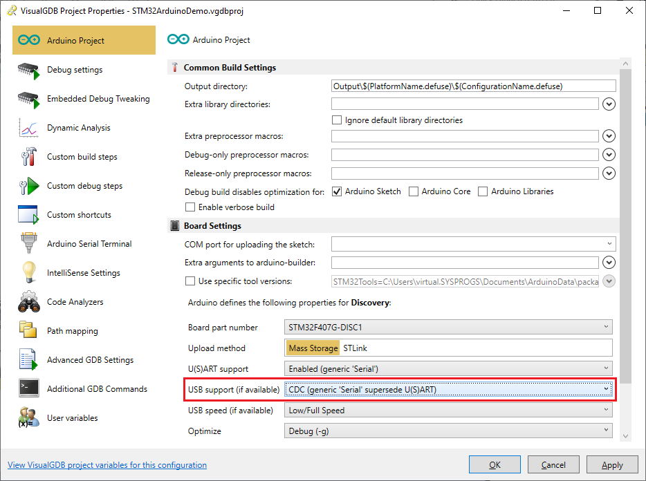
- Now we will show how to use the virtual COM port provided by the ESP32 Arduino cores. Open VisualGDB Project Properties and set the “USB Support” setting to “CDC”:
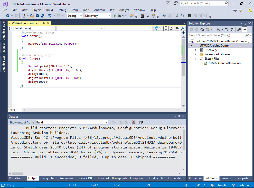
- Add the following line inside the loop() function:
Serial.print("Hello\r\n");
Then build the project and start debugging it:
- Most ST development boards have 2 USB connectors. The first one is connected to the on-board ST-Link, while the second one is connected to the target device. Locate the second USB connector on your board and ensure it is plugged in:
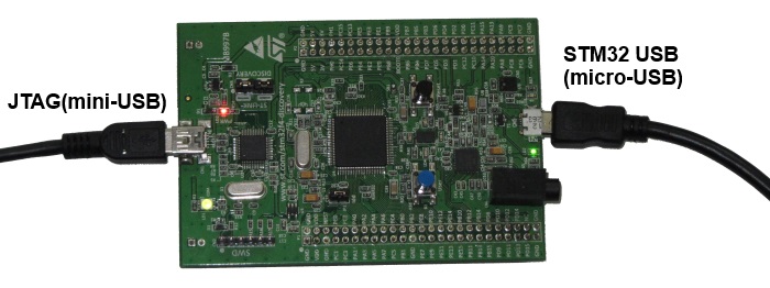 Once you connect it, the board will be recognized as a USB-based COM port.
 - Open VisualGDB project Properties and set the COM port for uploading the sketch to the virtual COM port:
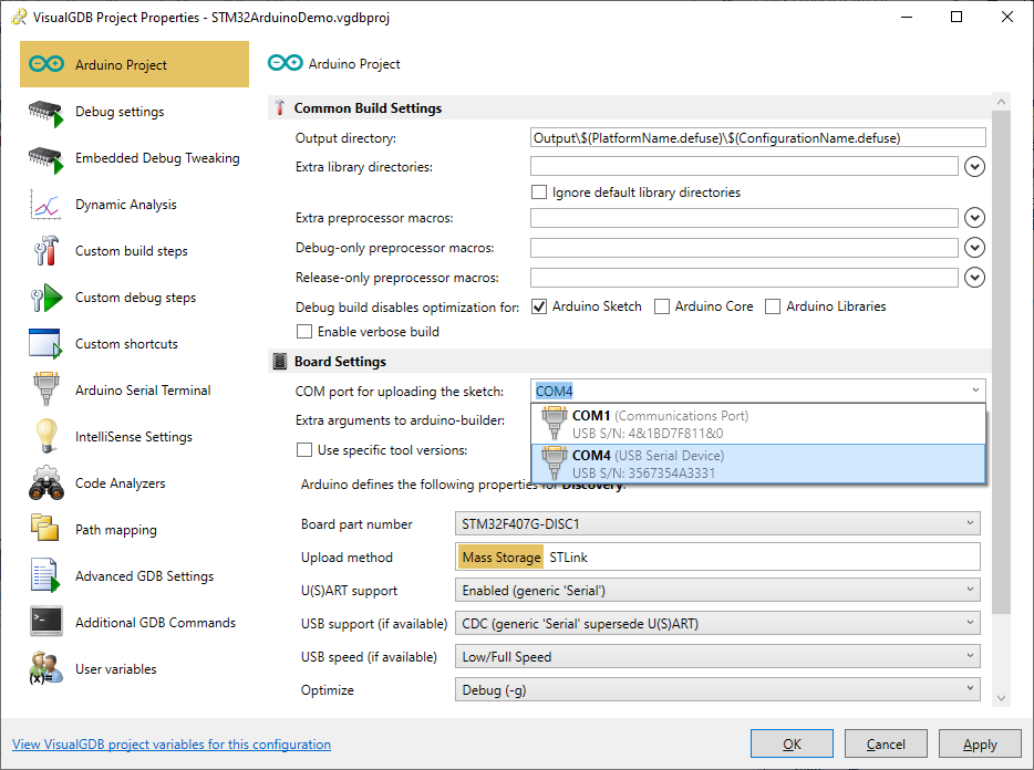 Note that unlike other Arduino targets, STM32 targets do not actually use the Arduino-level COM port for programming the FLASH memory. Hence it will only be used to view the program output.
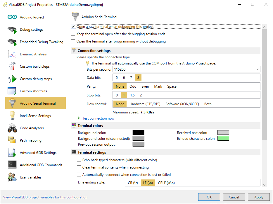
 - Go to the Arduino Serial Terminal page of VisualGDB Project Properties and enable the raw terminal:
- Restart debugging. You will now see the output from the Serial.print() method inside Visual Studio:
