Customizing Memory Layout of Embedded Programs with GNU Linker Scripts
This tutorial shows how to use linker scripts to control the memory layout of your embedded programs. We will create a basic “Blinking LED” program, add a new global variable to it and will use the linker script to place this variable in several specific memory locations. Before you begin, install VisualGDB 5.3 or later.
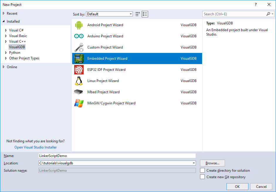
- Start Visual Studio and open the VisualGDB Embedded Project Wizard:
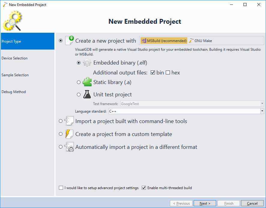
- Proceed with creating a new MSBuild-based project:
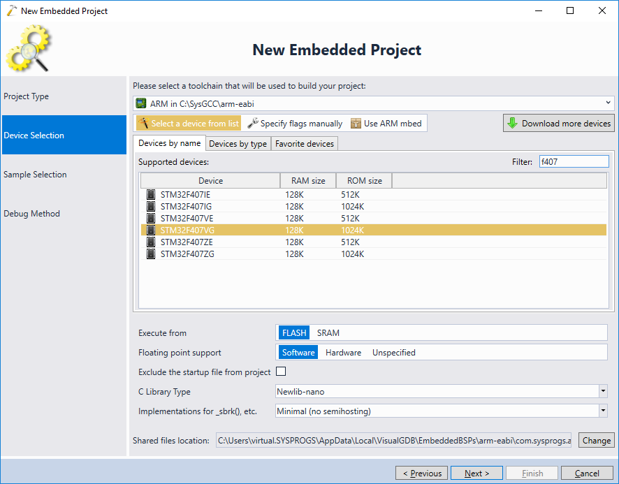
- On the Device Selection page pick the toolchain and the device. In this tutorial we will use the STM32F4Discovery board and hence will select the STM32F407VG device:
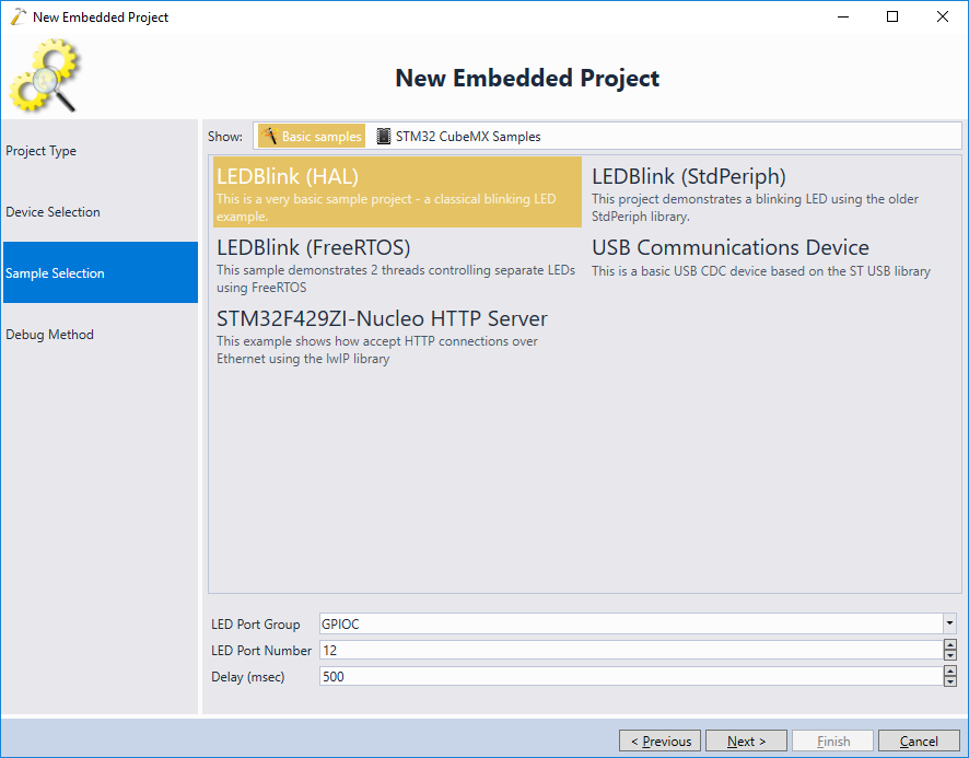
- Select a sample project to clone. In this tutorial we will pick the simplest “LEDBlink” project:
- Connect your debugger to the USB port and let VisualGDB detect it, or simply choose it from the list:
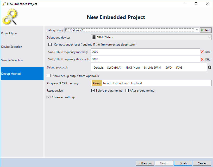
- Press “Finish” to generate the project. Then open VisualGDB Project Properties, go to MSBuild Settings page and click “Linker Script -> Copy to project directory”:

- Locate the linker script in Solution Explorer and open it:
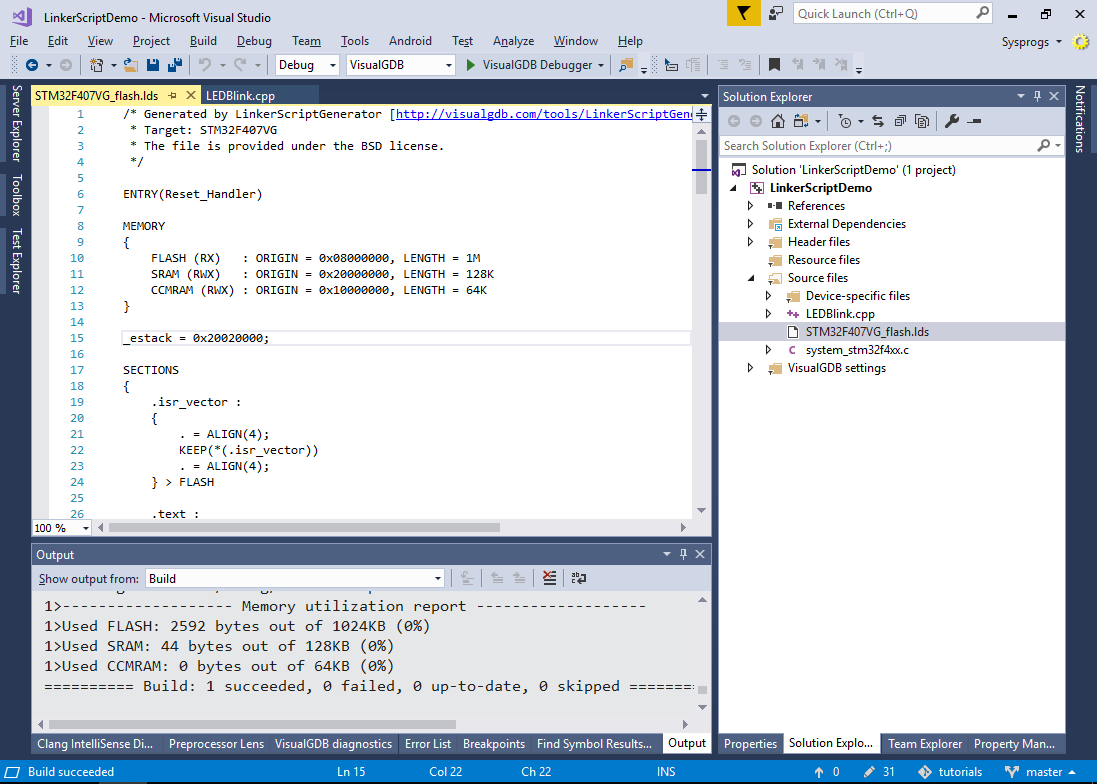
- Each linker script consists of the 2 main parts:
- Definition of the memory regions, such as SRAM and FLASH.
- Rules that define where each part of the program (e.g. functions, variables or special artifacts such as the interrupt vector table) gets placed.
Parts of the program with similar properties (e.g. all regular functions) are often grouped into sections – consecutive regions of memory sharing the same attributes. In this example, the first section going into the FLASH memory is .isr_vector.
You can see to see the result of the linker script (i.e. the addresses assigned to each section and symbol in your program) by generating the map files as shown below: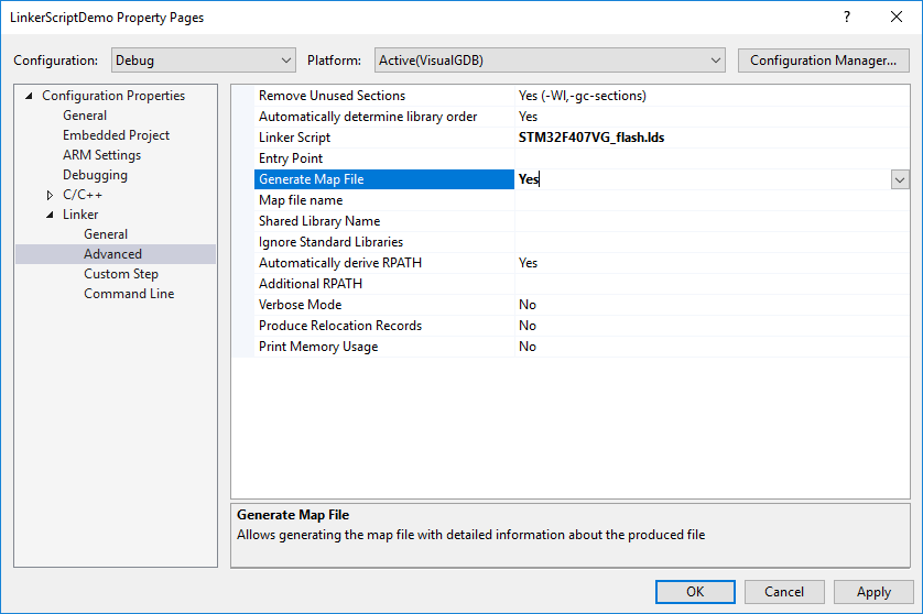
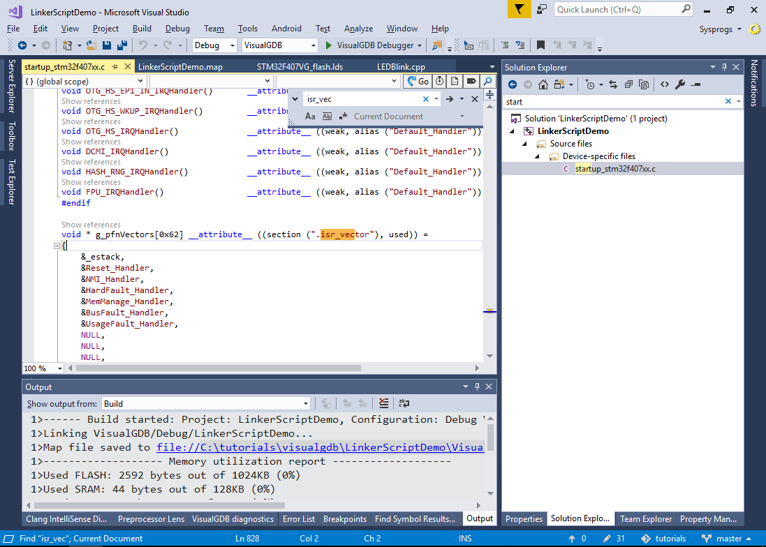
- Build the project and open the map file shown in the build output. Then search for .isr_vector in it:
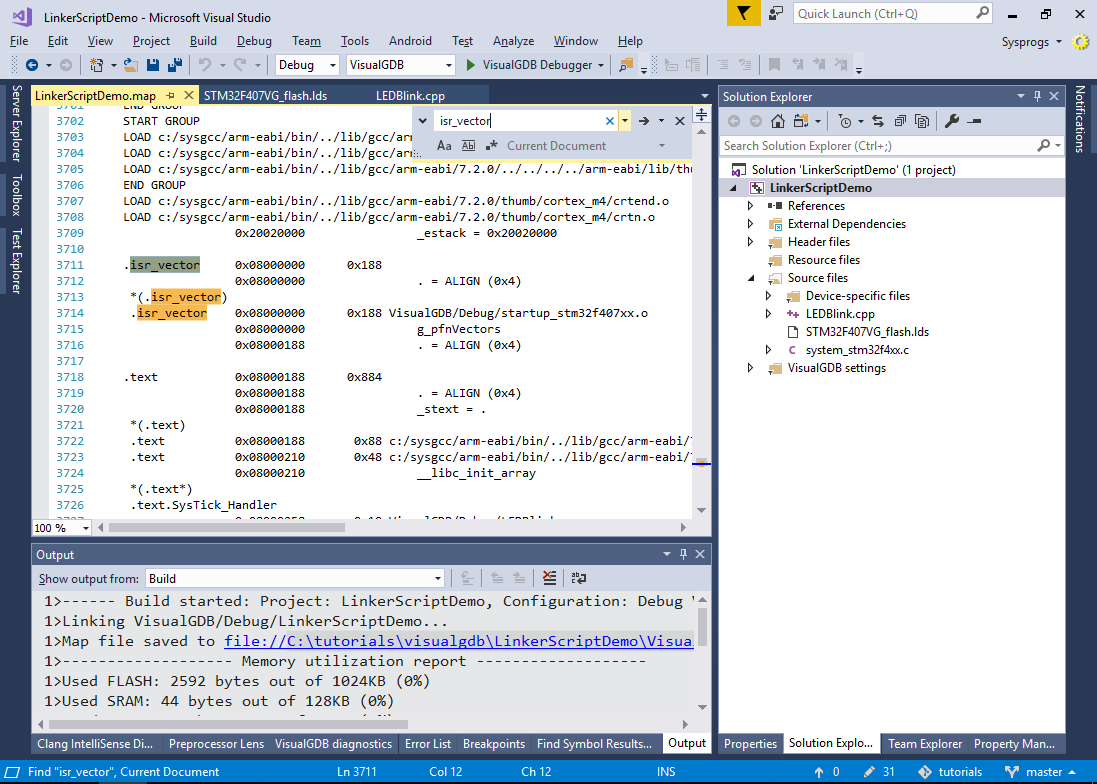 See how the .isr_vector section containing the g_pfnVectors variable got placed at the 0x08000000 address (beginning of the FLASH memory as defined in the linker script).
 - Search for the g_pfnVectors variable in the source files. See how it is explicitly placed into the “.isr_vector” section using the “section” attribute:
 Regular functions and variables that do not have a “section” attribute will be placed into the “.text.<function name>” and “.data.<variable name>” sections. Having one section per function or variable allows linker to automatically discard the unused functions (the linker can drop the sections not referenced by any other section).
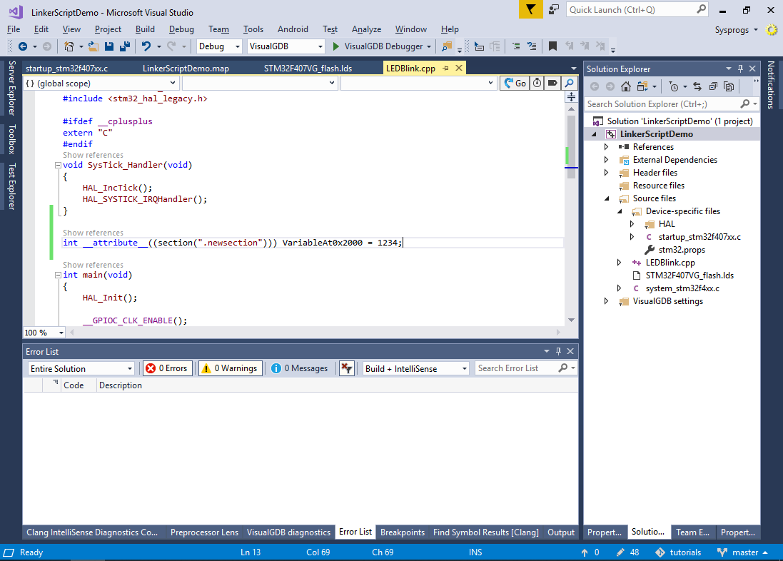
 - Now we will add a new global variable and use the “section” attribute together with some linker script constructs to place it at a fixed location in the memory. Add the following code to your main source file:
int __attribute__((section(".newsection"))) VariableAt0x2000 = 1234;
- Now add the following lines inside the .isr_vector section definition:
. = 0x2000;
KEEP(*(.newsection))
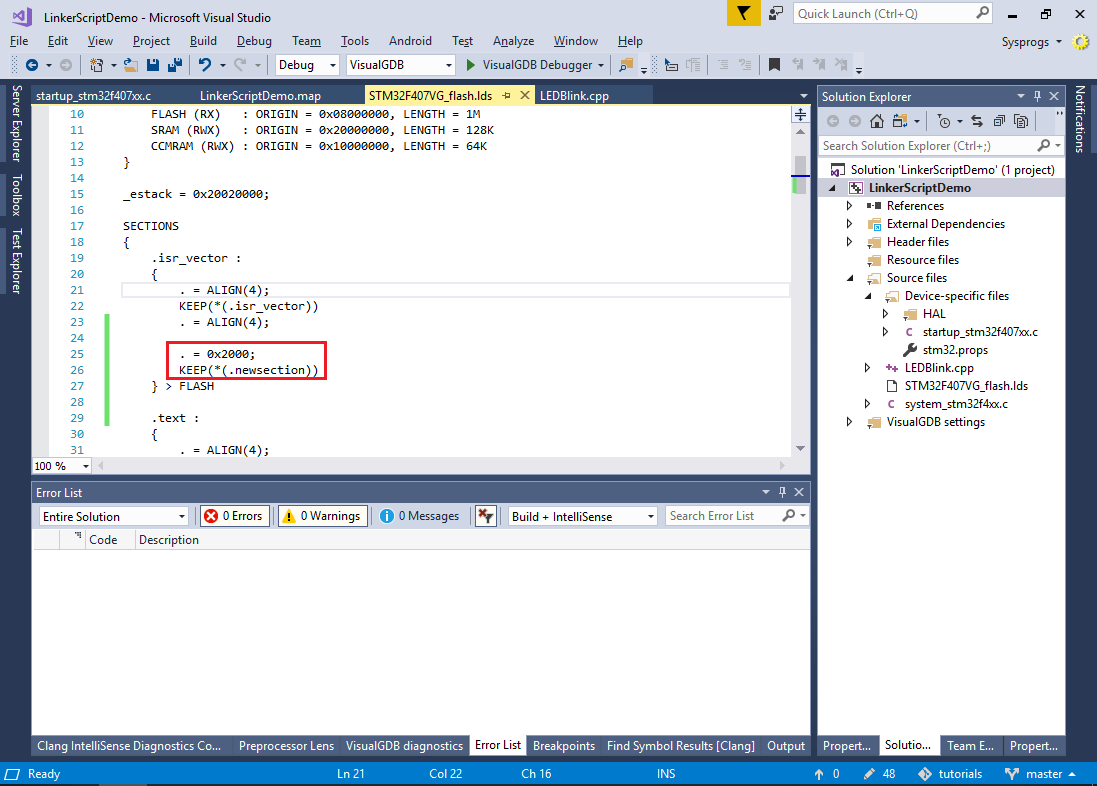 The “. = 0x2000” statement sets the “current address” pointer to 0x2000 (counting from the beginning of the section) and the *(.newsection) places the contents of the “.newscetion” sections from all source files at the current location. The KEEP() construct forces the linker to keep the sections in the final executable file even if they are not referenced by any other code (as we have not referenced the VariableAt0x2000 variable from any code, it would have normally been discarded).
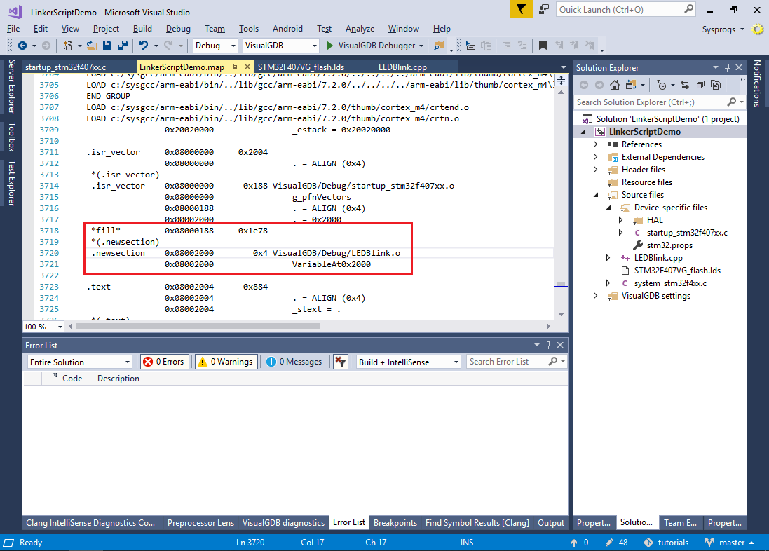
 - Build the project again and check the map file. See how the VariableAt0x2000 got placed inside the .isr_vector section exactly at the 0x08002000 address:
- If you want to align the variable at a certain boundary (e.g. 0x1000) instead of hardcoding the address, you can use the ALIGN() keyword as shown below:
.isr_vector :
{
	. = ALIGN(4);
	KEEP(*(.isr_vector))
	. = ALIGN(4);

	FILL(0xff)
	. = ALIGN(0x1000);
	KEEP(*(.newsection))
} > FLASH
This will result in the following output:
 *(.isr_vector)
 .isr_vector    0x08000000      0x188 VisualGDB/Debug/startup_stm32f407xx.o
                0x08000000                g_pfnVectors
                0x08000188                . = ALIGN (0x4)
 FILL mask 0xff
                0x08001000                . = ALIGN (0x1000)
 *fill*         0x08000188      0xe78 ff
 *(.newsection)
 .newsection    0x08001000        0x4 VisualGDB/Debug/LEDBlink.o
                0x08001000                VariableAt0x2000
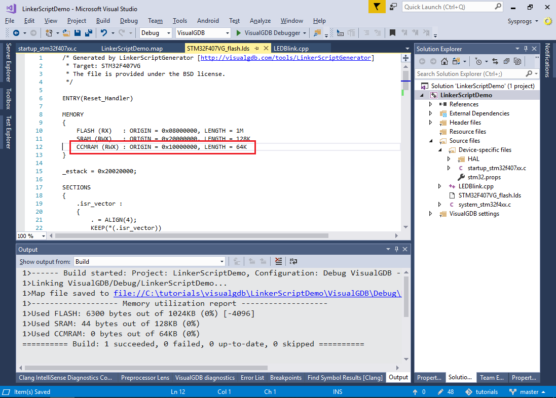
- Now we will try placing our global variable inside another memory. The STM32F407VG device includes 64 kilobytes of CCMRAM (see the linker script), so we will place our variable there:
 If your device has a single RAM region, you can split it into 2 parts by editing the MEMORY part of the linker script to try out the techniques from the rest of the tutorial.
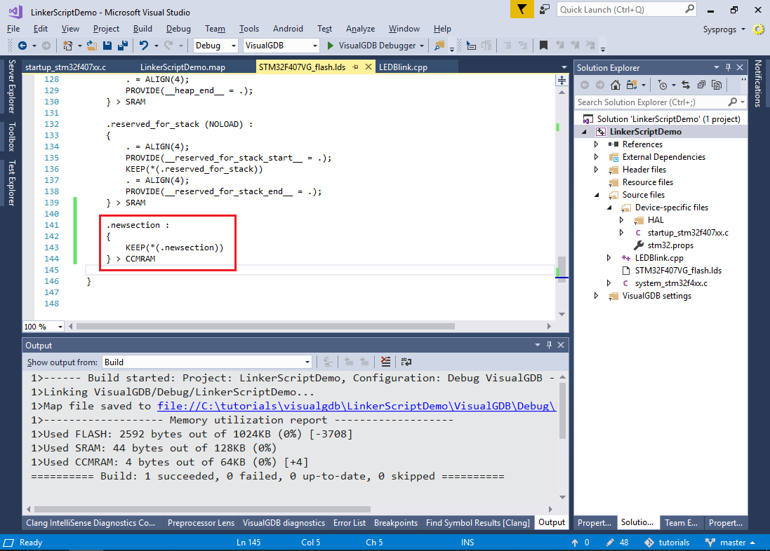
 - Remove the “.newsection” reference from .isr_vector and place it into a separate section at the end of the SECTIONS part of the linker script:
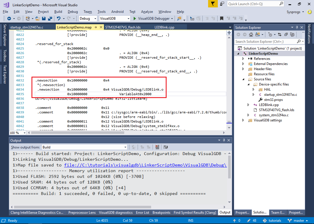
- Build the project and check the map file. See how the VariableAt0x2000 got placed to 0x10000000 (beginning of CCMRAM):
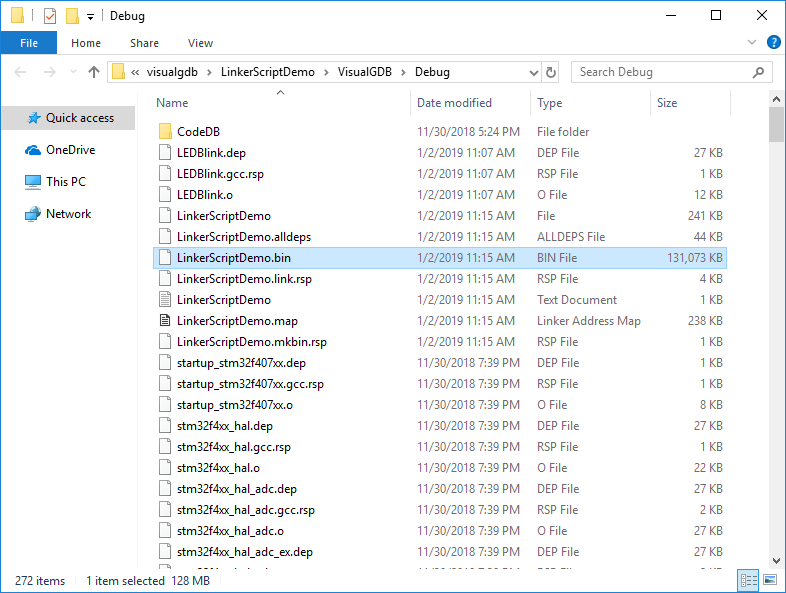
- Despite being placed at the correct address, this memory layout will have several side effects that we will explain below. First of all, locate the .bin file generated for your project. Depending on the exact memory address of .newsection, it can be several megabytes to gigabytes long:
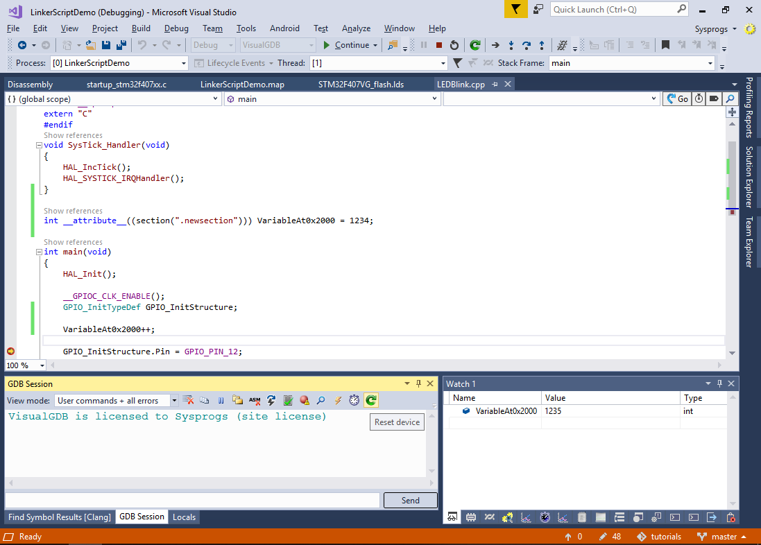
- Then try modifying the variable from your program and run it. First time you start a debug session, the variable value will be correct:
- However, if you try resetting the program, you will see that the variable value will not be changed from the previous run (in this example it was incremented from 1234 to 1235 in the previosu run and got further incremented to 1236 just now):
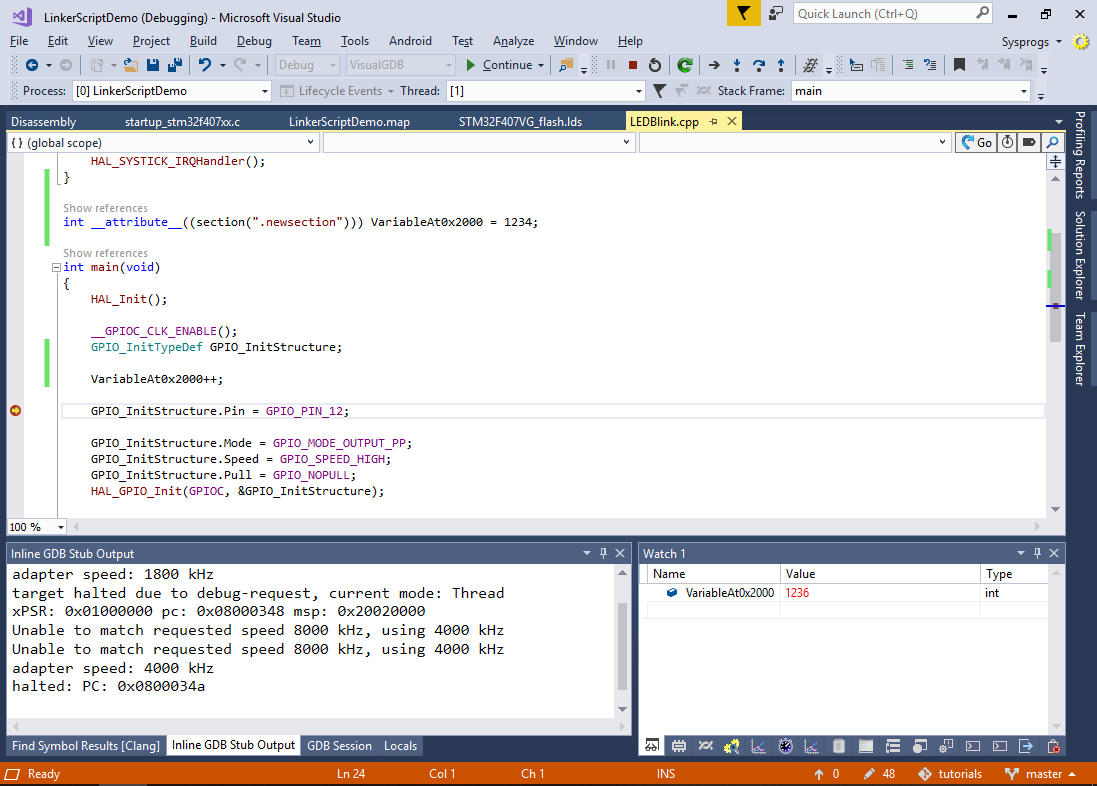
Furthermore, if you try power-cycling your device and attach to the program without programming it, the variable in CCMRAM will not be initialized at all (depending on your device type, it will have either a value of 0, or a random value). - Both the .bin file size and the incorrect initialization happen due to the same reason. Simply placing a variable at the address of 0x10000000 would make the tools act as if it was a part of the FLASH memory:
- The .bin file will contain a single consecutive snapshot of the target memory space between the lowest and the highest address in the ELF file (i.e. between g_pfnVectors at 0x08000000 and VariableAt0x2000 at 0x10000000).
- When you program the FLASH memory, gdb will physically copy the initial value of VariableAt0x2000 to the address of 0x10000000 where it will stay until the device is power-cycled.
- One quick way to fix it would be to declare .newsection with the NOLOAD attribute:
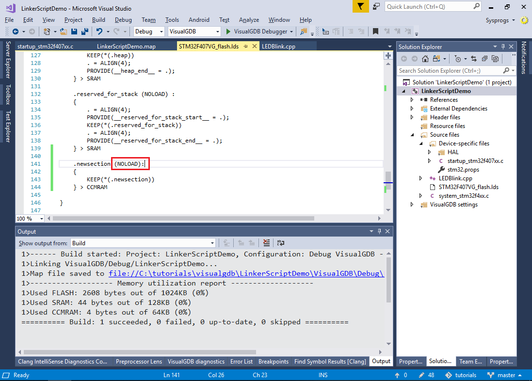 This will prevent the objcopy tool from including its contents into the .bin file and gdb won’t program it either. Then you could manually assign the initial value of VariableAt0x2000 from main() as the initial value specified in the variable definition will be ignored.
 - A better way to fix this would be using a separate load address for .newsection. The load address specifies the location where the section contents (i.e. the 1234 value) will be physically loaded when programming the FLASH memory or generating the .bin file. Since only the FLASH memory retains the data written there after a power cycle, the load address should be located within it. Modify the .newsection definition as shown below to load its contents right after the contents of the .data section (last section loaded into the FLASH memory):
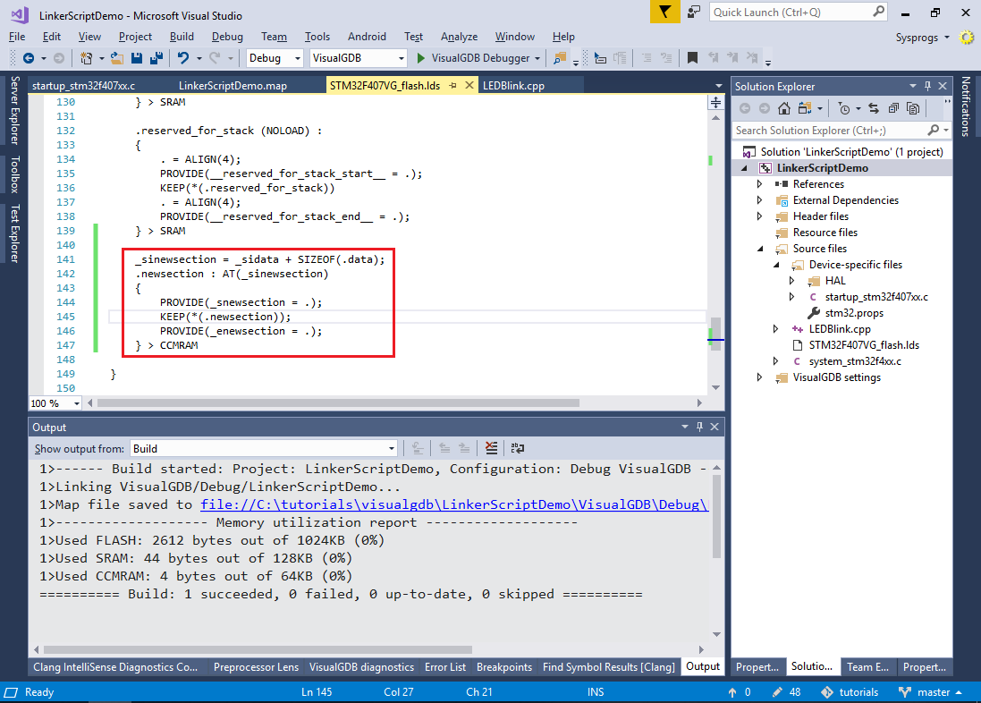 The _sinewsection (Start of Initialization data for .newsection), _snewsection (Start of .newsection) and _enewsection (End of .newsection) symbols will be used later to copy the data from FLASH into the actual CCMRAM.
 - Build the project and run the arm-eabi-objdump tool to see the addresses of various sections:
arm-eabi-objdump -h <ELF file>
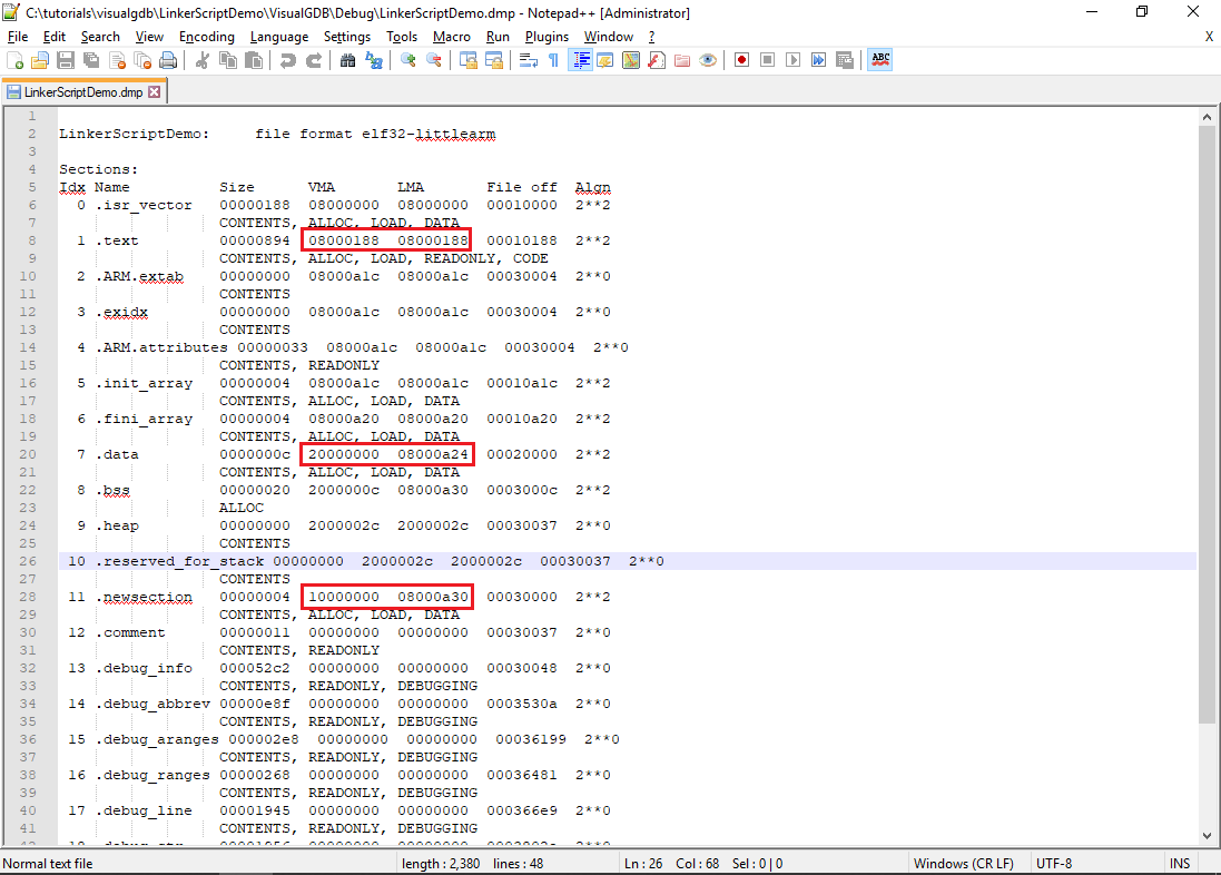 Note that the VMA (virtual memory address) specifies to address where the program will expect the section contents to be at runtime (e.g. “int x = VariableAt0x2000” will be translated to “int x = *((int *)0x10000000)”. The LMA (load memory address) specifies the address where the section contents will be placed during memory programming (see how it points within the FLASH memory for both .data and .newsection sections).
 - The only missing step is to actually copy the initial value of the VariableAt0x2000 to its virtual address. This could be done using the _sinewdata, _snewdata and _enewdata symbols:
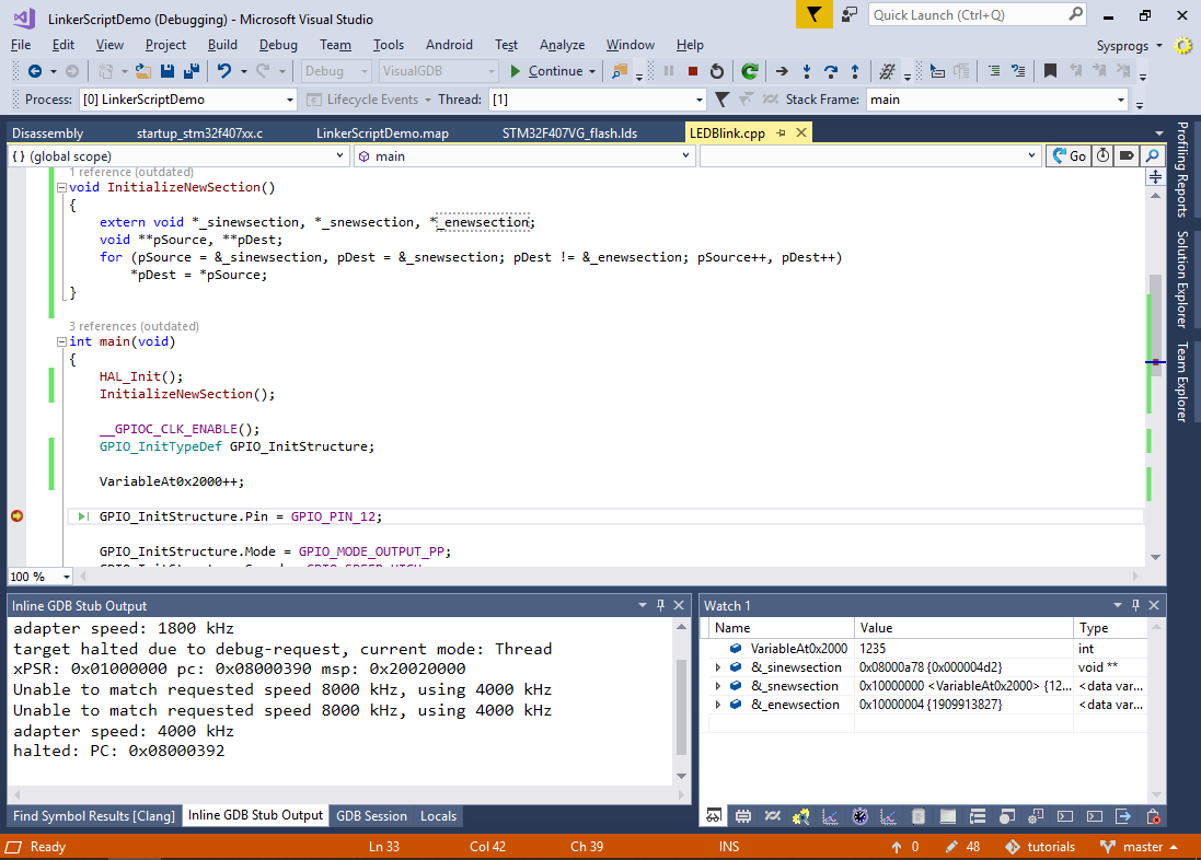
void InitializeNewSection()
{
    extern void *_sinewsection, *_snewsection, *_enewsection;
    void **pSource, **pDest;
    for (pSource = &_sinewsection, pDest = &_snewsection; pDest != &_enewsection; pSource++, pDest++)
        *pDest = *pSource;
}
Note that this will copy the correct values for ALL variables inside .newsection as they will be automatically placed between the _snewsection and _enewsection symbols.
- Power cycle the board and start debugging, checking the value of VariableAt0x2000. See how it got initialized to 1234 inside InitializeNewSection() and incremented in main():
If you are using the Custom edition of VisualGDB or higher, you can use the External Memories page of VisualGDB Project Properties to define additional memories like CCMRAM and let VisualGDB edit the linker script and generate the initialization code for you automatically.