Developing Projects for the i.MX RT Devices with Visual Studio
This tutorial shows how to create a basic project targeting the i.MX RT device using Visual Studio and VisualGDB. Before you begin, install VisualGDB 5.4 Beta 2 or later. We will create a basic “Blinking LED” project for the IMXRT1050-EVB board and will show how to debug it using Segger J-Link and the on-board CMSIS-DAP-compatible interface.
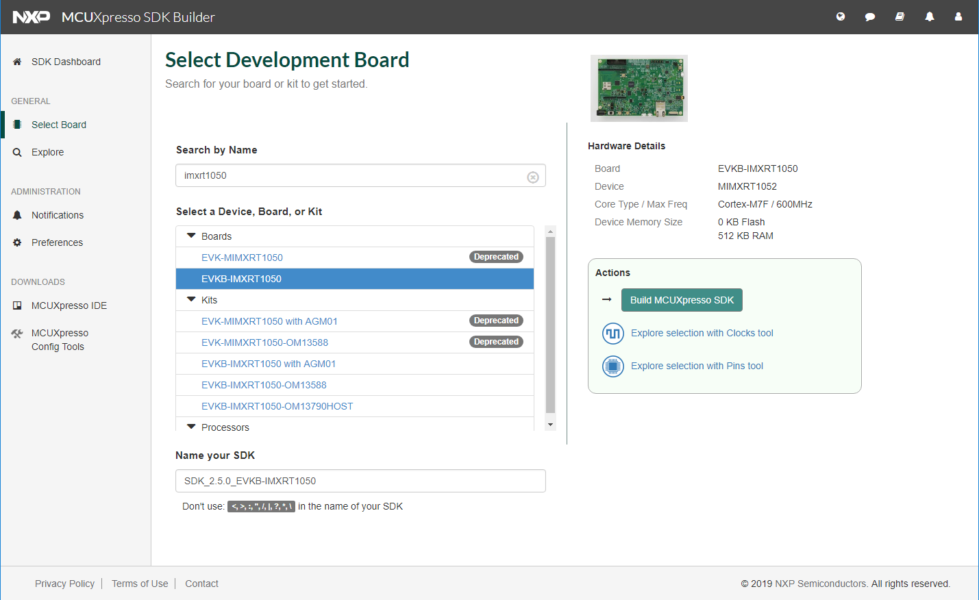
- The i.MX RT devices do not come with a regular stand-alone SDK. Instead, you need to generate an SDK for your board online. Open the MCUXpresso online SDK builder, select your board and click “Build MCUXpresso SDK”:
- Confirm your OS/toolchain settings (GCC ARM Embedded) and click “Download SDK”:

- Extract the downloaded SDK anywhere on your computer and open the VisualGDB Embedded Project Wizard:
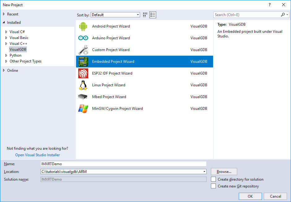
- On the first page of the wizard select “Create a new project with MSBuild”:

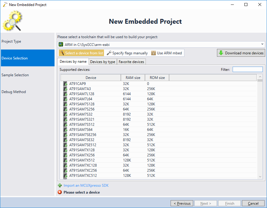
- On the second page of the wizard click “Import an MCUXpresso SDK”:
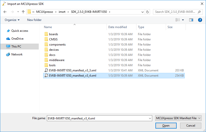
- Point VisualGDB to the folder where you have extracted the generated SDK:
- VisualGDB will import the SDK and display the i.MX RT devices in the device list. Select your device and click “Next”:

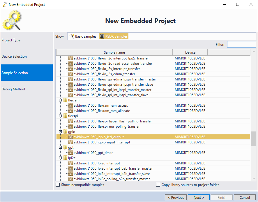
- As the SDK was imported automatically, it won’t contain any VisualGDB-supplied example projects. Click “KSDK Samples” to view the vendor-supplied samples instead. In this tutorial we will use use the “igpio_led_output” example:
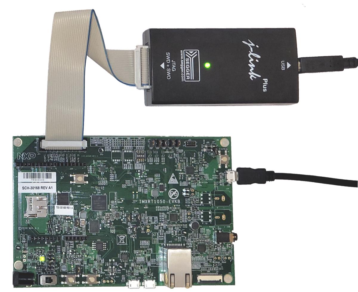
- The last page of the wizard allows configuring the debug interface. The easiest way to debug the i.MX RT devices would be using an external Segger J-Link device. It comes with out-of-the-box support for on-board FLASH memory programming and is much faster than the on-board CMSIS-DAP interface. Connect J-Link to the 20-pin JTAG connector and plug both J-Link and the board into the USB ports:
- Select “Segger J-Link” on the Debug Method page and click “Finish” to generate the project:

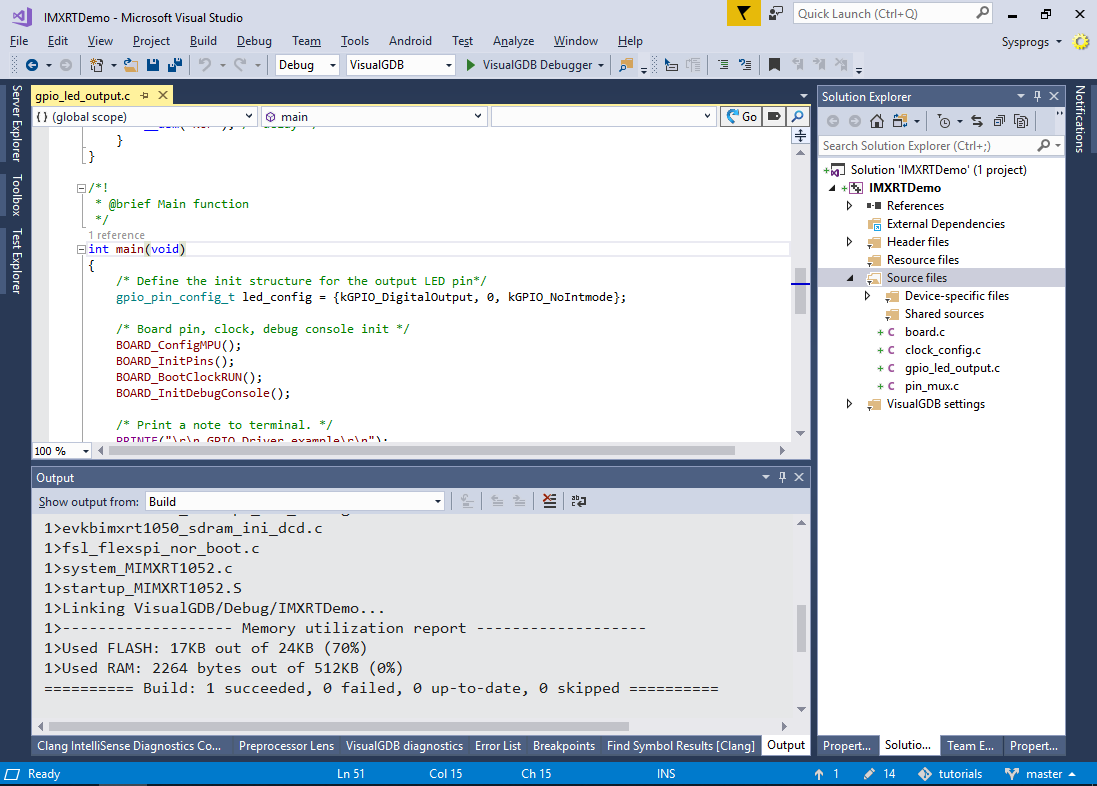
- Now you can build the project by pressing Ctrl-Shift-B:
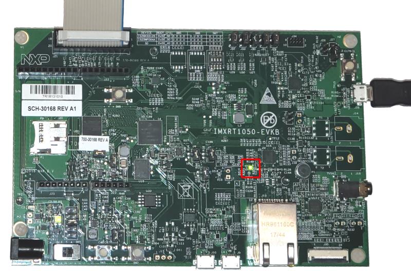
- Press F5 to begin debugging. Verify that the on-board LED is blinking:
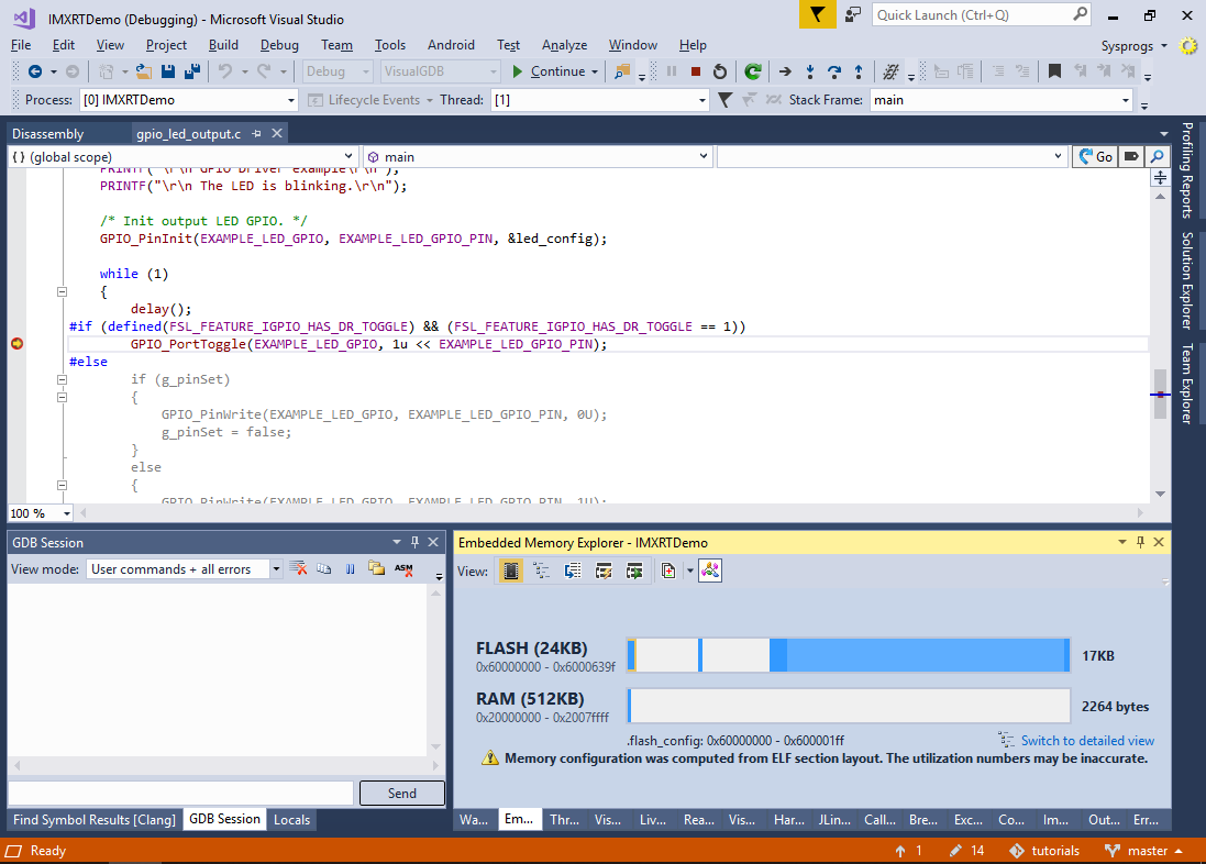
- Set a breakpoint near the GPIO_PortToggle() call and wait for it to trigger:
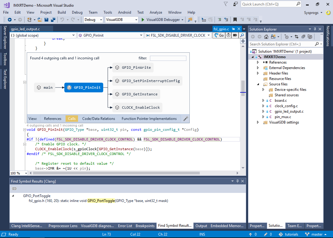
- You can use the regular debugging techniques to debug your program. As the imported project includes all the necessary code from the SDK, you can use the CodeJumps popups to explore relations between different parts of the program itself and the i.MX RT SDK:
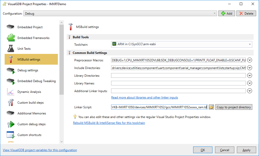
- Now we will show how to use the on-board CMSIS-DAP interface instead of Segger J-Link. Note that CMSIS-DAP is relatively slow and as of January 2019, the OpenOCD tool used to debug the board with it cannot program the on-board FLASH memory unless you create a FLASH programming plugin. In this tutorial we will switch the program to run entirely from SRAM in order to demonstrate CMSIS-DAP-based debugging. Open the MSBuild Settings page of VisualGDB Project Properties and locate the linker script:

- Change the linker script to the “xxxx_ram.ld” version:
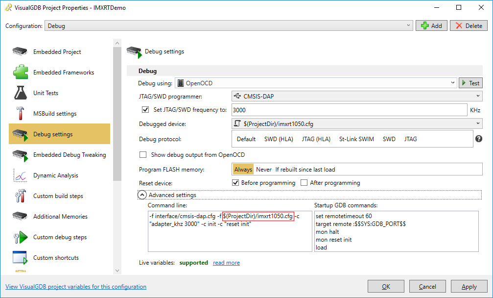
- Download this OpenOCD configuration script to your project directory. Then Go to the “Debug Settings” page, select “Debug Methods” instead of “USB Devices”, pick OpenOCD, choose CMSIS-DAP as the JTAG/SWD programmer and edit the OpenOCD command line to use the configuration file from the project directory:
 Now you will be able to debug your program using the on-board CMSIS-DAP interface. If you would like to program the on-board FLASH memory using OpenOCD instead of the J-Link software, you can create a FLASH programming plugin similar to the one described in this tutorial.