Developing an LCD application for the STM32F7-Discovery with VisualGDB and OpenOCD
This tutorial shows how to create an application that will display a basic animation on the LCD screen of the STM32F7-Discovery board. We will show how to:
- Access the LCD controller framebuffer
- Access the DRAM memory
- Embed binary resources in your firmware
- Build and debug STM32F7 firmware with OpenOCD and Visual Studio
Before you begin, install VisualGDB 5.0 or later and follow our basic STM32F7 tutorial to ensure that your board can be programmed.
- Start Visual Studio and open VisualGDB Embedded Project wizard:
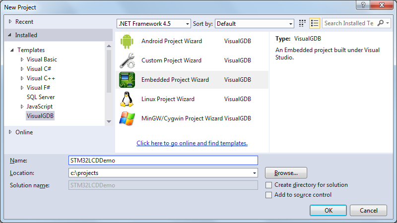
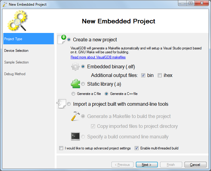
- Proceed with creating a new project:
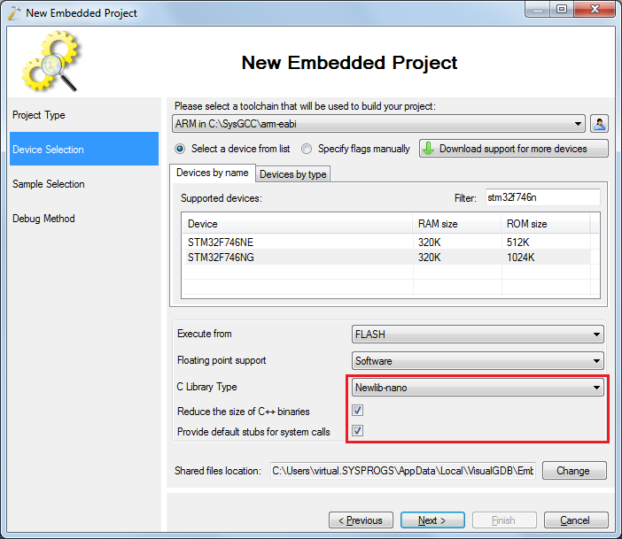
- Select the ARM toolchain and pick your device from the list. To save space, select newlib-nano and ensure that both checkboxes below it are set:
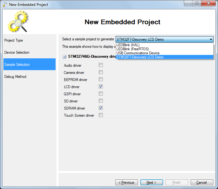
- On the next page select the LCD Demo sample:
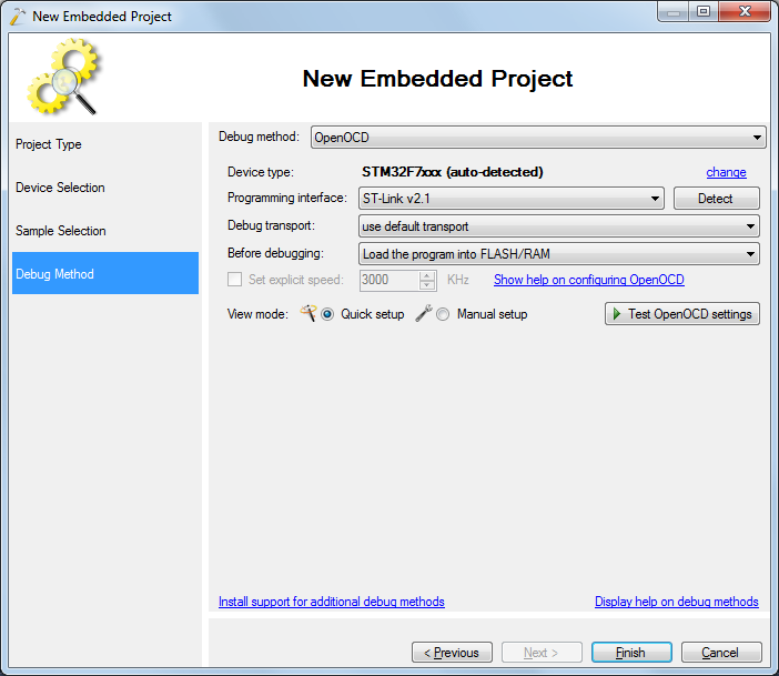
- On the last page of the wizard select the debug method you want to use. We will use OpenOCD with the on-board ST-Link interface:
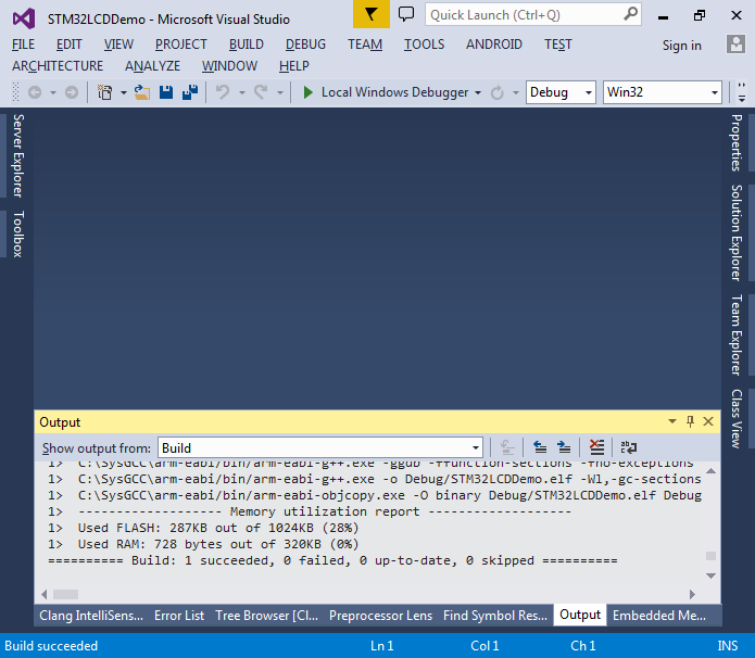
- Press “Finish” to create your project and build it using the Build Solution command:
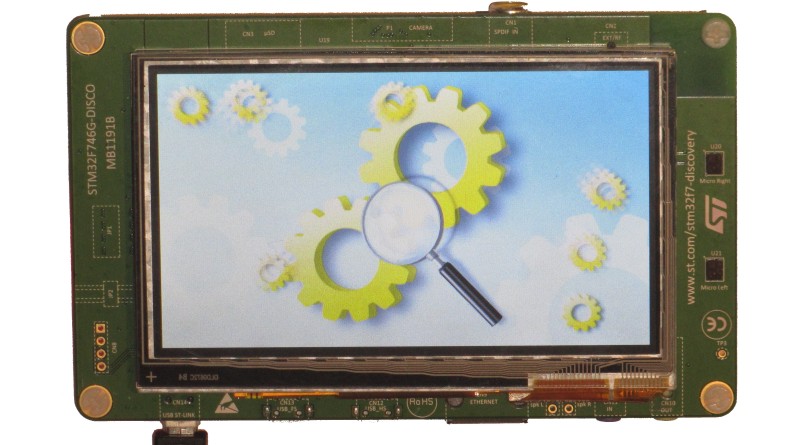
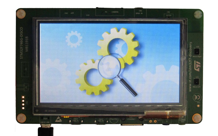
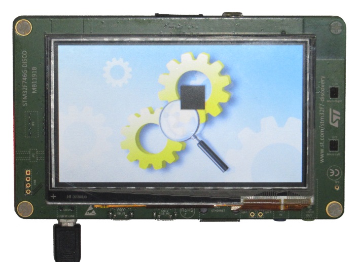
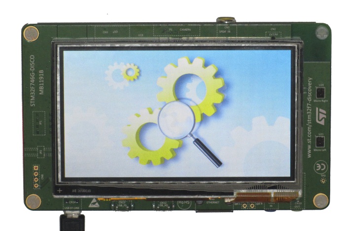
- Press F5 to start debugging. VisualGDB will program the FLASH memory and start your program. The display will show a static image:
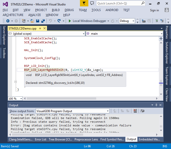
- Now we will modify the program to show something dynamic. Go to the definition of the BSP_LCD_LayerRgb565Init() function that is responsible for initializing the LCD controller:
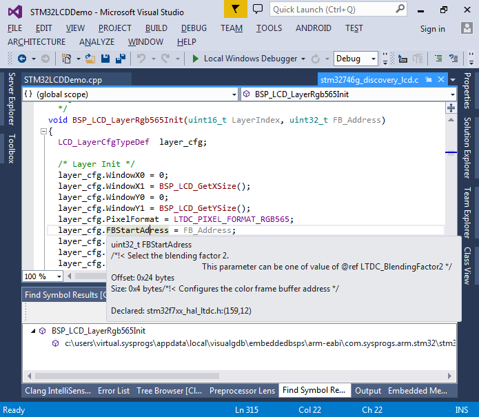
- The framebuffer address is stored in the FBStartAddress field of the layer configuration structure:
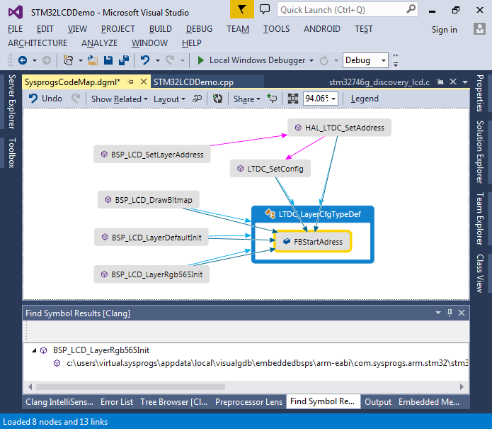
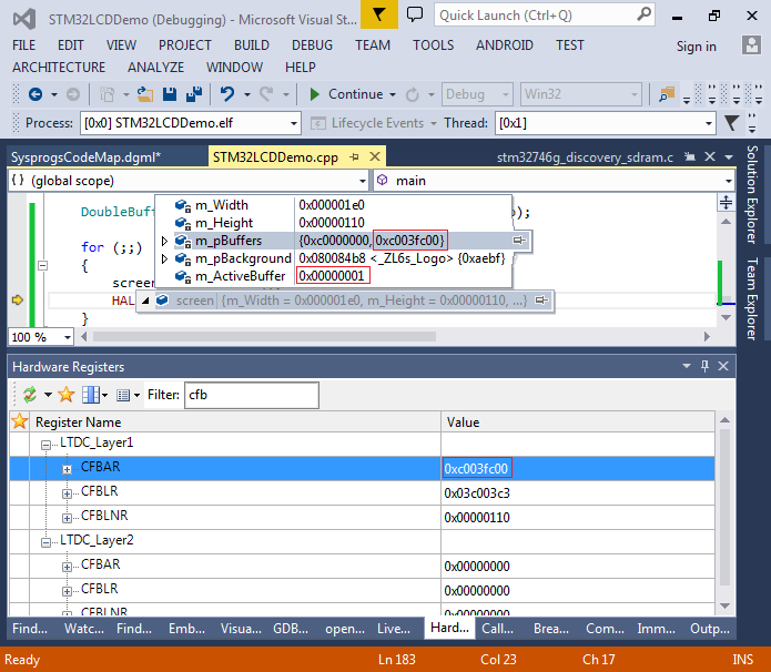
- Use the Code Map to display the functions accessing the field and the functions calling them. This should give a good overview of the LCD setup functions. In particular, we will be using the HAL_LDTC_SetAddress() function to change the address of the frame buffer:
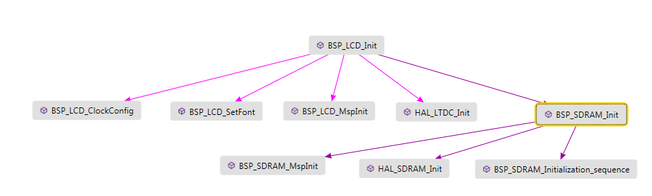
- You can also use the CodeMap to verify that BSP_LCD_Init() actually initializes the DRAM controller:
- Before we can place data into DRAM, we will make a very basic allocator with no free() function that will allocate DRAM memory dynamically so that we don’t need to handle it at compile time:
#include <string.h>
#include <algorithm>

class OneWayAllocator
{
private:
    char *m_pData;
    int m_RemainingSize;

public:
    OneWayAllocator(void *pData, int remainingSize)
        : m_pData((char *)pData)
        , m_RemainingSize(remainingSize)
    {
    }

    void *Allocate(size_t size)
    {
        if (size >= m_RemainingSize)
        {
            asm("bkpt 255");
            return NULL;
        }
        void *pResult = m_pData;
        m_RemainingSize -= size;
        m_pData += size;
        return pResult;
    }
};

OneWayAllocator g_DRAMAllocator((void *)LCD_FB_START_ADDRESS, 8 * 1024 * 1024);
The LCD_FB_START_ADDRESS constant is equal to 0xC0000000 and it specifies the DRAM address.
- Now we can add a double-buffered screen object that will allocate 2 buffers and use one of them as the framebuffer while the other one is used to draw the next frame:
class DoubleBufferedScreen
{
private:
    int m_Width, m_Height;
    uint16_t *m_pBuffers[2];
    uint16_t *m_pBackground;
    int m_ActiveBuffer;

public:
    DoubleBufferedScreen(int width, int height, uint16_t *pBackground)
        : m_Width(width)
        , m_Height(height)
        , m_pBackground(pBackground)
        , m_ActiveBuffer(0)
    {
        m_pBuffers[0] = (uint16_t *)g_DRAMAllocator.Allocate(width * height * sizeof(m_pBuffers[0][0]));
        m_pBuffers[1] = (uint16_t *)g_DRAMAllocator.Allocate(width * height * sizeof(m_pBuffers[0][0]));
        memcpy(m_pBuffers[0], m_pBackground, m_Width * m_Height * sizeof(m_pBuffers[0][0]));
        memcpy(m_pBuffers[1], m_pBackground, m_Width * m_Height * sizeof(m_pBuffers[0][0]));
    }

    uint16_t *GetBackBuffer()
    {
        return m_pBuffers[!m_ActiveBuffer];
    }

    void SwitchBuffer()
    {
        m_ActiveBuffer = !m_ActiveBuffer;
        BSP_LCD_SetLayerAddress(0, (uint32_t)m_pBuffers[m_ActiveBuffer]);
    }

    int GetWidth()
    {
        return m_Width;
    }

    int GetHeight()
    {
        return m_Height;
    }

    int GetBackBufferIndex()
    {
        return !m_ActiveBuffer;
    }
};
- Initially both buffers will just contain the background picture and we will not draw anything extra:
-
    DoubleBufferedScreen screen(480, 272, (uint16_t *)s_Logo);

    for (;;)
    {
        screen.SwitchBuffer();
        HAL_Delay(10);
    }
- Compile your program, start it and verify that the background picture is shown like before. Then use the debugger to verify that the layer 1 of the LCD controller is using the currently active screen for the framebuffer:
- Now we will add a widget class. The widget will have 2 main methods:
- Draw itself on a screen
- Restore the background in the area occupied by itself
This will ensure that we won’t need to copy the entire image background each time:
void DrawPixels(uint16_t *pDst, const uint16_t *pSrc, int pixels)
{
    for (int i = 0; i < pixels; i++)
        pDst[i] = pSrc[i];
}

class Widget
{
private:
    int m_Width, m_Height;
    uint16_t *m_pData;
    DoubleBufferedScreen *m_pScreen;

    int m_X, m_Y;

    int m_BufferedX[2], m_BufferedY[2];
public:
    Widget(DoubleBufferedScreen *pScreen, int width, int height, uint16_t *pData)
        : m_Width(width)
        , m_Height(height)
        , m_pData(pData)
        , m_X(0)
        , m_Y(0)
        , m_pScreen(pScreen)
    {
        m_BufferedX[0] = m_BufferedX[1] = m_X;
        m_BufferedY[0] = m_BufferedY[1] = m_Y;
    }

    ~Widget()
    {
    }

    void Draw()
    {
        if (m_X > m_pScreen->GetWidth() || m_Y > m_pScreen->GetHeight())
            return;

        int todoX = std::min(m_pScreen->GetWidth() - m_X, m_Width);
        int todoY = std::min(m_pScreen->GetHeight() - m_Y, m_Height);

        for (int y = 0; y < todoY; y++)
            DrawPixels(m_pScreen->GetBackBuffer() + (y + m_Y) * m_pScreen->GetWidth() + m_X, m_pData + y * m_Width, todoX);

        int bufIndex = m_pScreen->GetBackBufferIndex();
        m_BufferedX[bufIndex] = m_X;
        m_BufferedY[bufIndex] = m_Y;
    }

    void RestoreBackground(uint16_t *pBackground)
    {
        int bufIndex = m_pScreen->GetBackBufferIndex();
        int myX = m_BufferedX[bufIndex], myY = m_BufferedY[bufIndex];

        if (myX > m_pScreen->GetWidth() || myY > m_pScreen->GetHeight())
            return;

        int todoX = std::min(m_pScreen->GetWidth() - myX, m_Width);
        int todoY = std::min(m_pScreen->GetHeight() - myY, m_Height);

        for (int y = 0; y < todoY; y++)
            DrawPixels(m_pScreen->GetBackBuffer() + (y + myY) * m_pScreen->GetWidth() + myX, pBackground + (y + myY) * m_pScreen->GetWidth() + myX, todoX);
    }

    int GetX()    { return m_X; }
    int GetY()    { return m_Y; }
    int GetWidth()    { return m_Width; }
    int GetHeight()    { return m_Height; }

    void Move(int deltaX, int deltaY)
    {
        m_X = std::max(m_X + deltaX, 0);
        m_Y = std::max(m_Y + deltaY, 0);
    }
};
Note that the DRAM controller will generate a memory fault in case of an unaligned 32-bit access, so we need to use a function that uses 16-bit accesses. It can be further optimized by using 32-bit accesses after doing 0 or 1 initial 16-bit accesses.
- We will also add a class responsible for moving the widgets:
class WidgetMover
{
private:
    Widget *m_pWidget;
    DoubleBufferedScreen *m_pScreen;
    int m_XSpeed, m_YSpeed;

public:
    WidgetMover(DoubleBufferedScreen *pScreen, Widget *pWidget, int xSpeed, int ySpeed)
        : m_pWidget(pWidget)
        , m_pScreen(pScreen)
        , m_XSpeed(xSpeed)
        , m_YSpeed(ySpeed)
    {
    }

    void Step()
    {
        if (m_pWidget->GetX() <= 0 && m_XSpeed < 0)
            m_XSpeed = -m_XSpeed;
        if (m_pWidget->GetY() <= 0 && m_YSpeed < 0)
            m_YSpeed = -m_YSpeed;

        if (m_pWidget->GetX() + m_pWidget->GetWidth() >= m_pScreen->GetWidth() && m_XSpeed > 0)
            m_XSpeed = -m_XSpeed;
        if (m_pWidget->GetY() + m_pWidget->GetHeight() >= m_pScreen->GetHeight() && m_YSpeed > 0)
            m_YSpeed = -m_YSpeed;

        m_pWidget->Move(m_XSpeed, m_YSpeed);
    }

    Widget *GetWidget()
    {
        return m_pWidget;
    }
};
- Finally, add code to main() that will draw a moving black square bouncing off the screen edges:
    const int WidgetSize = 48;
    DoubleBufferedScreen screen(480, 272, (uint16_t *)s_Logo);
    uint16_t *pSquare = (uint16_t*)g_DRAMAllocator.Allocate(WidgetSize * WidgetSize * sizeof(uint16_t));
    memset(pSquare, 0, WidgetSize * WidgetSize * sizeof(uint16_t));

    Widget widget(&screen, WidgetSize, WidgetSize, pSquare);
    WidgetMover mover(&screen, &widget, 1, 1);

    for (;;)
    {
        screen.SwitchBuffer();
        widget.RestoreBackground((uint16_t*)s_Logo);
        mover.Step();
        widget.Draw();
    }
- Run your program and observe the moving square:
- You may notice some flickering that happens because we start modifying a buffer without waiting for the LCD controller to finish the previous frame and actually switch the frame buffer. To wait for the end of frame add the following line at the end of SwitchBuffer():
while (!(LTDC->CDSR & LTDC_CDSR_VSYNCS)) {}
- Now we will replace the black square with a transparency-enabled bitmap from an image file. We will display the following image:
 However, instead of decompressing the PNG format on the device, we will use the following C# program to convert it into a raw ARGB format:
using System.IO;
using System.Linq;
using System.Text;
using System.Threading.Tasks;

namespace ImageConverter
{
    class Program
    {
        static void Main(string[] args)
        {
            Bitmap bmp = new Bitmap(args[0]);
            List<byte> data = new List<byte>();
            for (int y = 0; y < bmp.Height; y++)
                for (int x = 0; x < bmp.Width; x++)
                {
                    Color pixel = bmp.GetPixel(x, y);

                    data.Add(pixel.A);
                    data.Add(pixel.R);
                    data.Add(pixel.G);
                    data.Add(pixel.B);
                }
            File.WriteAllBytes(Path.ChangeExtension(args[0], ".dat"), data.ToArray());
        }
    }
}
- Run the program on the image file (or download its output here) and place the output file into your project directory. Now we need to include it into the ELF file. Add the following rule to your Makefile right after the .cxx rule:
$(BINARYDIR)/%.o : %.dat
    $(TOOLCHAIN_ROOT)/bin/arm-eabi-ld -r -b binary $< -o $@
Then update the source_objs assignment to include .dat files:
source_obj1 := $(all_source_files:.cpp=.o)
source_obj2 := $(source_obj1:.c=.o)
source_obj3 := $(source_obj2:.s=.o)
source_obj4 := $(source_obj3:.S=.o)
source_obj5 := $(source_obj4:.cc=.o)
source_obj6 := $(source_obj5:.cxx=.o)
source_objs := $(source_obj6:.dat=.o)
- Then add the .dat file to the project same way as you add source files (you can put it into a separate folder in Solution Explorer) and build the project:
 By modifying the Makefile we have created a rule template that will run the ld.exe on each .dat file included into the project converting it onto an object file. By adding the .dat file to the Solution Explorer we instructed VisualGDB to include it in the source file list (VisualGDB checks the rules in the Makefile to determine source extensions). Each object file created from a binary file will contain a symbol called _binary_<file name>_start allowing to reference it from your code.
 - Now we will a function for drawing images with transparency:
void DrawWithTransparency(uint16_t *pDst, const uint32_t *pSrc, int pixels)
{
    for (int i = 0; i < pixels; i++)
    {
        uint16_t oldPixel = pDst[i];
        uint32_t value = pSrc[i];
        int oldR = ((oldPixel >> (5 + 6)) & 0x1F) << 3;
        int oldG = ((oldPixel >> 5) & 0x3F) << 2;
        int oldB = (oldPixel & 0x1F) << 3;

        int picWeight = value & 0xFF;
        int oldWeight = 256 - picWeight;

        int picR = (value >> 8) & 0xFF;
        int picG = (value >> 16) & 0xFF;
        int picB = (value >> 24) & 0xFF;

        int newR = (oldR * oldWeight + picR * picWeight) / 256;
        int newG = (oldG * oldWeight + picG * picWeight) / 256;
        int newB = (oldB * oldWeight + picB * picWeight) / 256;

        newR >>= 3;
        newG >>= 2;
        newB >>= 3;

        uint16_t rgb565 = (ushort)(newB | (newG << 5) | (newR << (5 + 6)));
        pDst[i] = rgb565;
    }
}
- We will call it instead of DrawPixels() from the Widget::Draw() method. Additionally, we will change the type of Widget::m_pData and the related constructor parameter to int32_t:
class Widget
{
    //...
    uint32_t *m_pData;
    //...
    Widget(DoubleBufferedScreen *pScreen, int width, int height, uint32_t *pData)
    {
        //...
    }

    //...

    void Draw()
    {
        //...
        for (int y = 0; y < todoY; y++)
            DrawWithTransparency(m_pScreen->GetBackBuffer() + (y + m_Y) * m_pScreen->GetWidth() + m_X, m_pData + y * m_Width, todoX);
        //...
    }
}
- Finally import the symbol produced when converting the .dat file in main() and pass its address to the constructor of the widget:
    extern uint32_t _binary_48x48_dat_start[];
    Widget widget(&screen, WidgetSize, WidgetSize, _binary_48x48_dat_start);
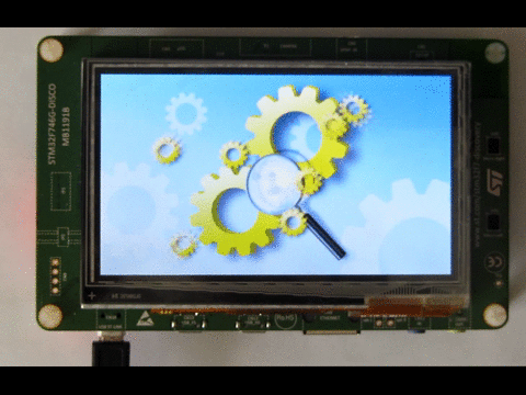
- Run your program and observe the moving gear icon:
- The code can be easily scaled to create several gear widgets each with its own speed:
    std::vector<WidgetMover *> widgets;
    for (int i = 0; i < 7; i++)
    {
        Widget *pWidget = new Widget(&screen, 48, 48, _binary_48x48_dat_start);
        pWidget->Move(rand() % screen.GetWidth(), rand() % screen.GetHeight());
        widgets.push_back(new WidgetMover(&screen, pWidget, i + 1, i + 1));
    }

    for (;;)
    {
        for (auto pWidget : widgets)
            pWidget->GetWidget()->RestoreBackground((uint16_t *)s_Logo);

        for (auto pWidget : widgets)
        {
            pWidget->Step();
            pWidget->GetWidget()->Draw();
        }
        screen.SwitchBuffer();
    }
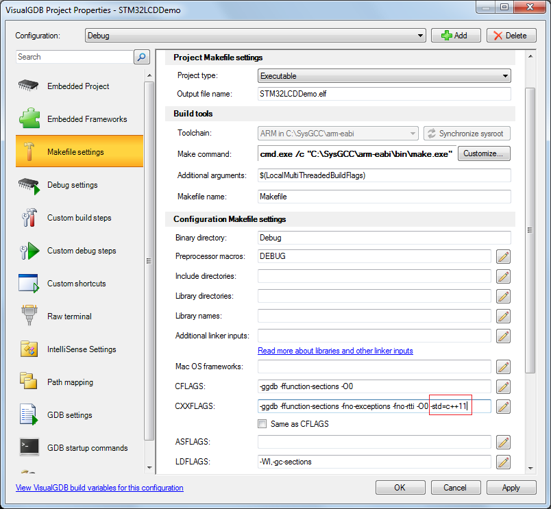
- Note that you will need to enable C++11 in Makefile Settings to use the range-based for loop:
- Build the new program and start it. Observe the 7 independently moving gear widgets:
 You can download the final version of the main .cpp file here.


