Developing C/C++ Firmware for the ESP32 WROVER Module
This tutorial shows how to create a basic project for the ESP32 WROVER-KIT-3 module, program the FLASH memory and debug it via the on-board JTAG. We will create a basic project that will blink the red, green and blue on-board LEDs from different FreeRTOS threads and will show how to debug it and change various configuration-related settings.
Before you begin, install VisualGDB 5.4 or later.
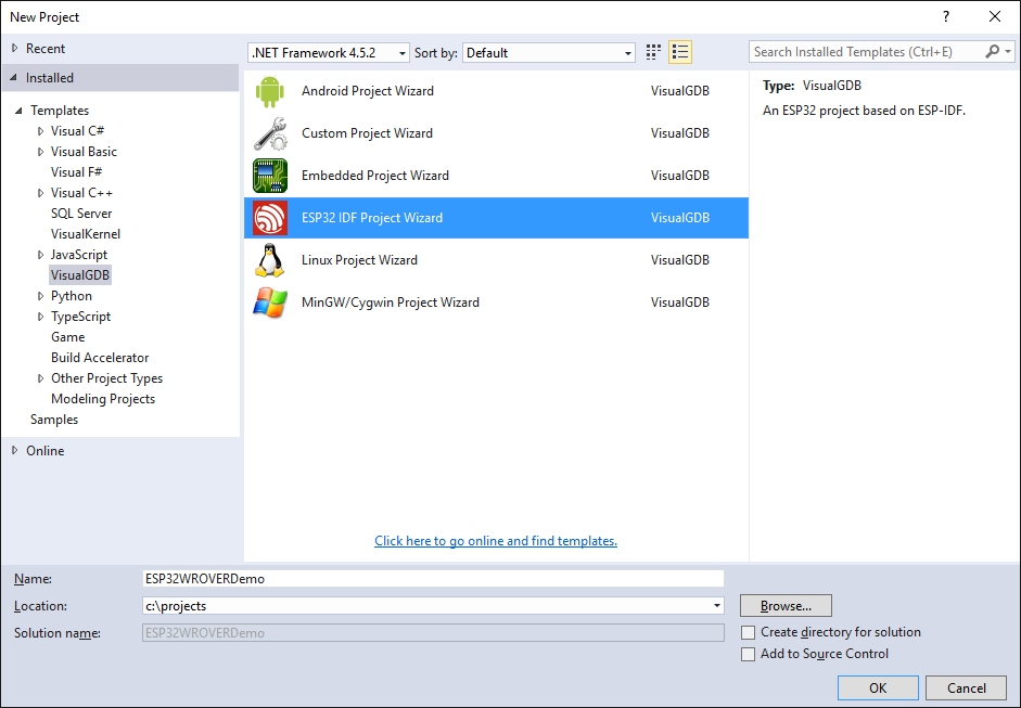
- Start Visual Studio and open the ESP-IDF project wizard:
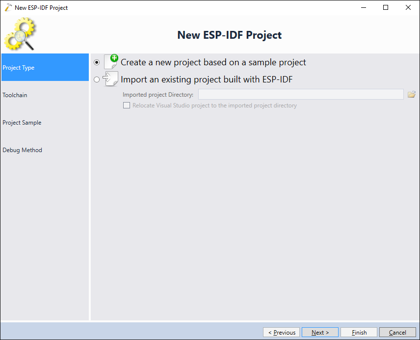
- Select “Create a new project based on a sample project”:
- On the next page select the location of your ESP32 toolchain. If you don’t have any toolchains installed yet, click “Download more toolchains” and VisualGDB will automatically install a compatible ESP32 toolchain:
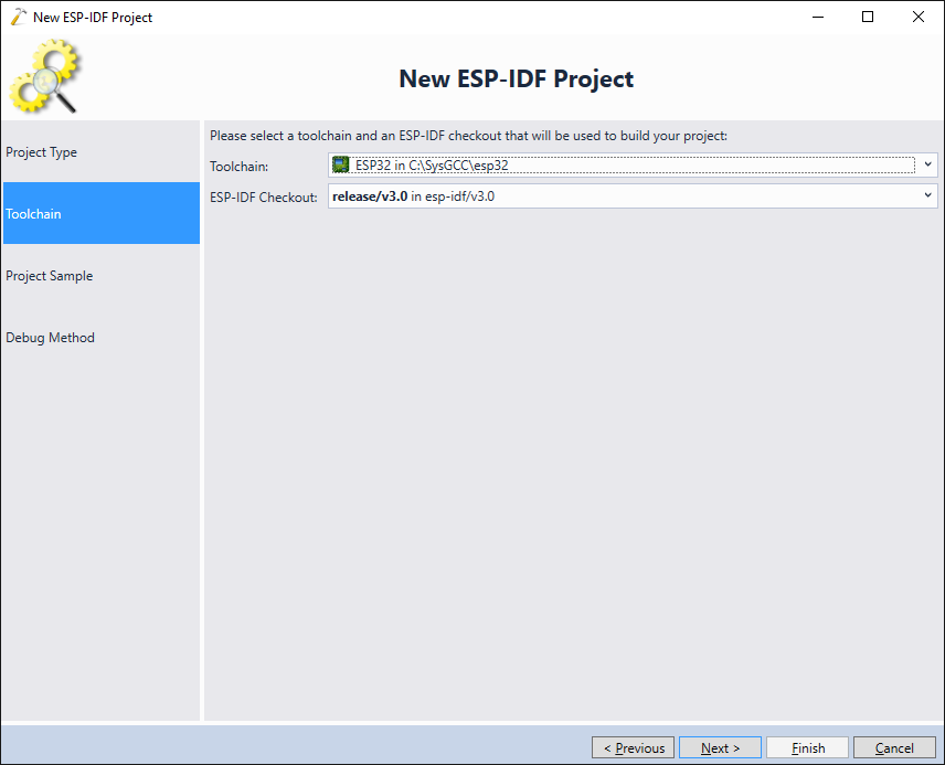 Update: For better compatibility with the latest ESP32 tools, we recommend selecting the consolidated toolchain instead.
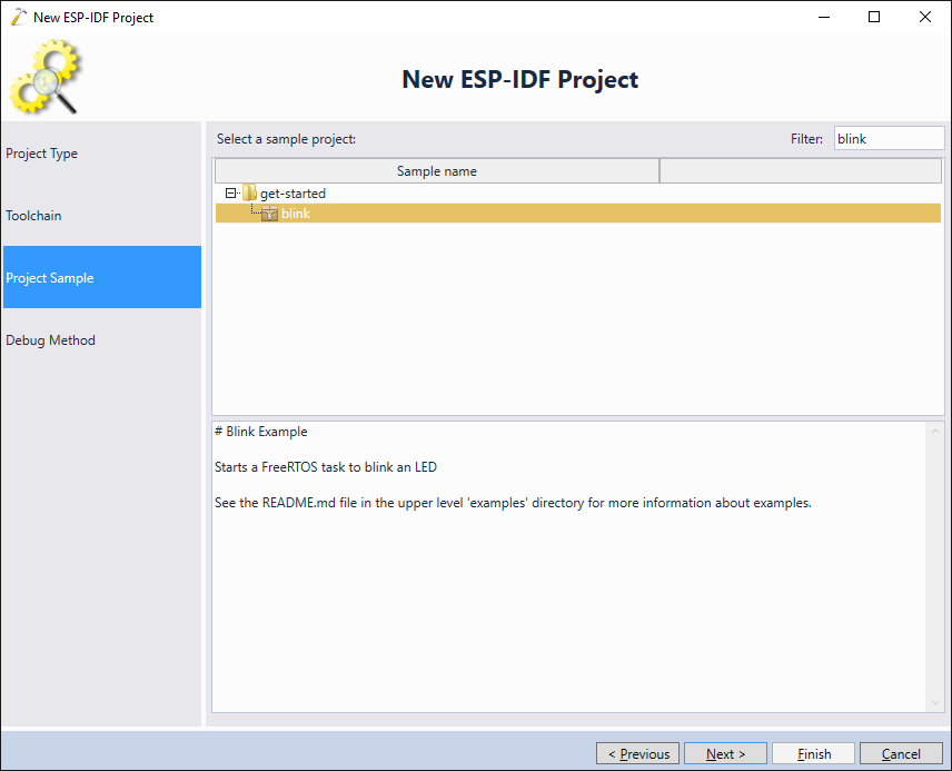
 - The next step is to select the sample project that will be used as a template for our project. Pick the “Blink” project from the “get-started” folder and click “next”:
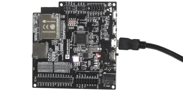
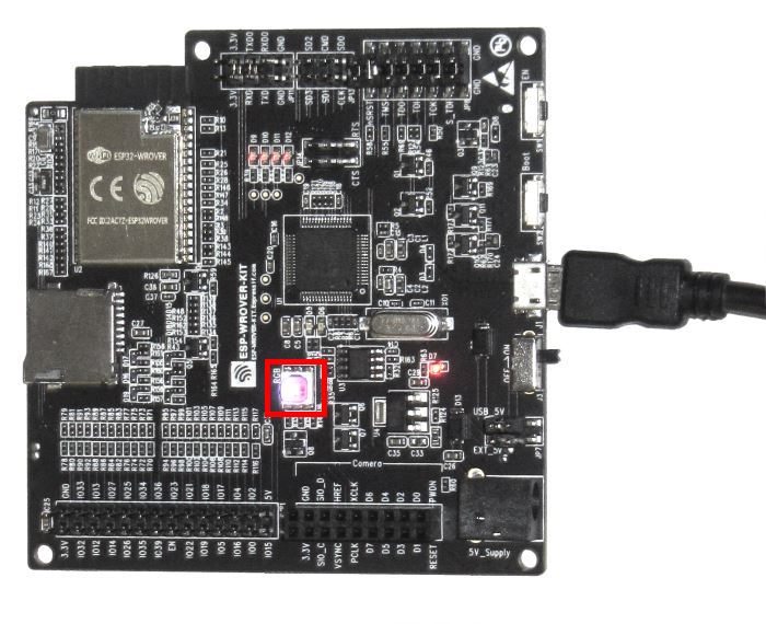
- In order to enable the on-board JTAG debugging functionality, install the 7 jumpers (may not included with the board) as shown below:
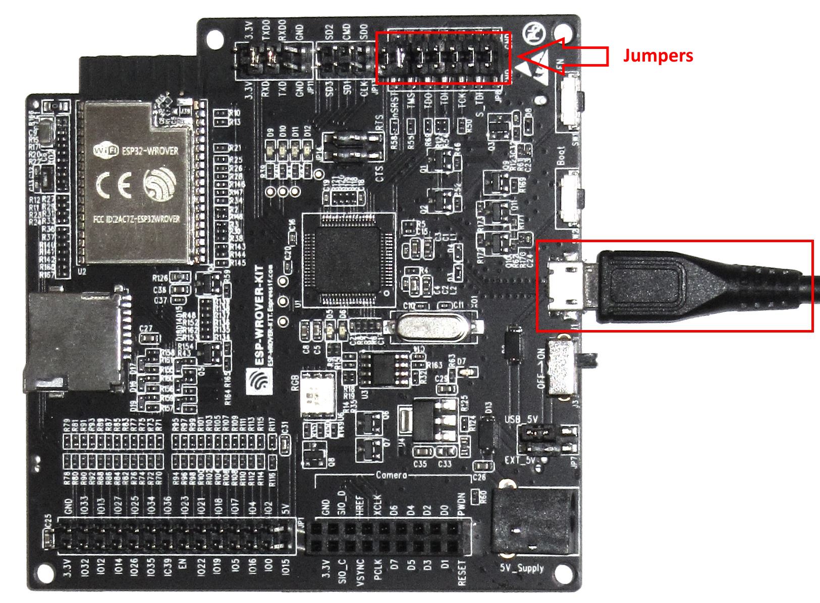 WARNING: the picture above shows the previous version of the ESP-WROVER board. If you are using ESP-WROVER v4.1 or later, see this page for the exact names and locations of the jumpers. Once the jumpers are installed, connect the board via USB.
 - VisualGDB should automatically recognize the board as long as you are using the latest ESP32 toolchain:
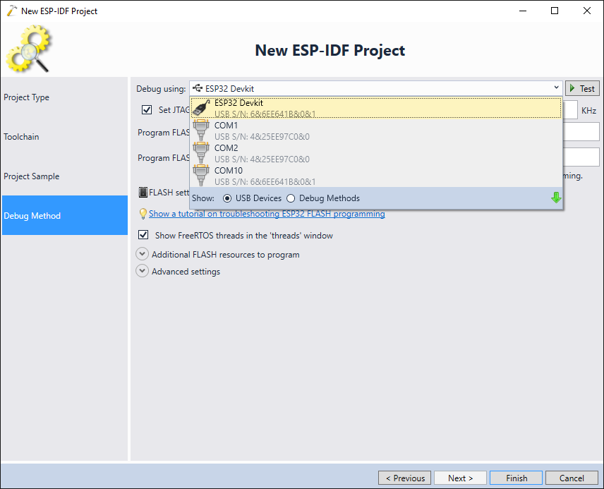
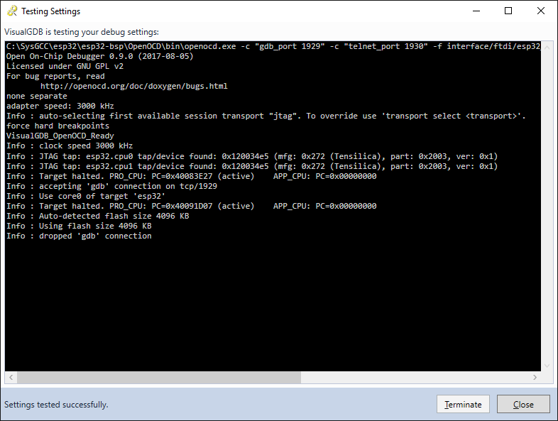
- Click “Test” to automatically test the JTAG connection. VisualGDB will automatically install all necessary drivers and will use the correct JTAG settings:
 Finally Press “Finish” to create the project.
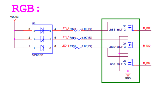
 - By default, the “ledblink” project will toggle the GPIO #5 that is not connected to any on-board LEDs. To change this, we will first need to look up the GPIO numbers for the RGB LED from the ESP-WROVER-KIT schematic:
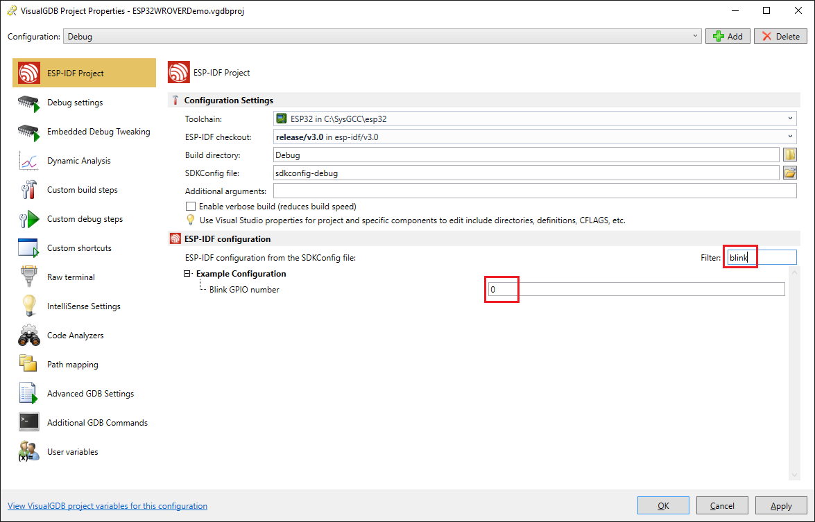
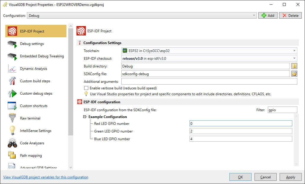
 Then open VisualGDB Project Properties and set the “Blink GPIO Number” to 0, corresponding to the red LED:
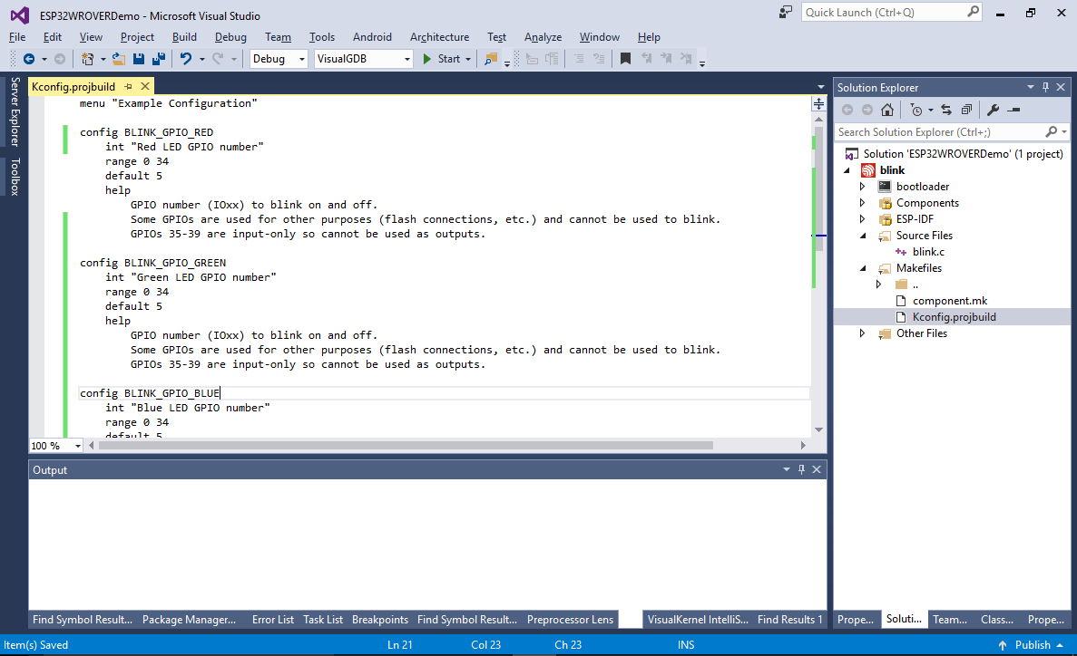
- If you build and run your project now, it will repeatedly blink the red LED. To support 3 independent LED channels, we will now modify the KConfig.projbuild file to have 3 separate configuration options instead of just 1:
menu "Example Configuration"

config BLINK_GPIO_RED
 int "Red LED GPIO number"
 range 0 34
 default 5
 help
 GPIO number (IOxx) to blink on and off.
 Some GPIOs are used for other purposes (flash connections, etc.) and cannot be used to blink.
 GPIOs 35-39 are input-only so cannot be used as outputs.

config BLINK_GPIO_GREEN
 int "Green LED GPIO number"
 range 0 34
 default 5
 help
 GPIO number (IOxx) to blink on and off.
 Some GPIOs are used for other purposes (flash connections, etc.) and cannot be used to blink.
 GPIOs 35-39 are input-only so cannot be used as outputs.

config BLINK_GPIO_BLUE
 int "Blue LED GPIO number"
 range 0 34
 default 5
 help
 GPIO number (IOxx) to blink on and off.
 Some GPIOs are used for other purposes (flash connections, etc.) and cannot be used to blink.
 GPIOs 35-39 are input-only so cannot be used as outputs.


endmenu
- Save the file and reopen VisualGDB Project Properties. Now you can set the pin numbers for the red, green and blue LEDs via the regular ESP-IDF configuration GUI:
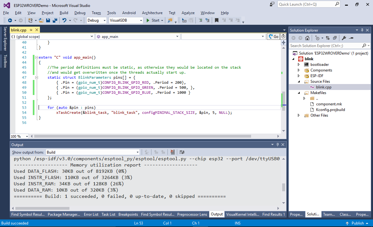
- Change the main file extension to .cpp and replace its contents with the following code:
struct BlinkParameters
{
    gpio_num_t Pin;
    unsigned Period;
};

void blink_task(void *pvParameter)
{
    struct BlinkParameters *pBlinkParameters = (struct BlinkParameters *)pvParameter;

    gpio_pad_select_gpio(pBlinkParameters->Pin);
    /* Set the GPIO as a push/pull output */
    gpio_set_direction(pBlinkParameters->Pin, GPIO_MODE_OUTPUT);
    while(1) {
        /* Blink off (output low) */
        gpio_set_level(pBlinkParameters->Pin, 0);
        vTaskDelay(pBlinkParameters->Period / 2 / portTICK_PERIOD_MS);
        /* Blink on (output high) */
        gpio_set_level(pBlinkParameters->Pin, 1);
        vTaskDelay(pBlinkParameters->Period / 2 / portTICK_PERIOD_MS);
    }
}

extern "C" void app_main()
{
    //The period definitions must be static, as otherwise they would be located on the stack
    //and would get overwritten once the threads actually start up.
    static struct BlinkParameters pins[] = {
        { .Pin = (gpio_num_t)CONFIG_BLINK_GPIO_RED, .Period = 200},
        { .Pin = (gpio_num_t)CONFIG_BLINK_GPIO_GREEN, .Period = 500, },
        { .Pin = (gpio_num_t)CONFIG_BLINK_GPIO_BLUE, .Period = 1000 }
    };

    for (auto &pin : pins)
        xTaskCreate(&blink_task, "blink_task", configMINIMAL_STACK_SIZE, &pin, 5, NULL);
}
It will create 3 instances of the blink_task thread, each one targeting a different LED with a different period:
- Press F5 to start debugging and observe the RGB LED. You will see each channel toggling with its own period:
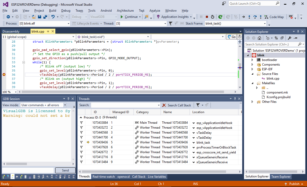
- Set a breakpoint after one of the gpio_set_level() calls. The breakpoint will get immediately triggered by one of the threads. You can see the other threads via the Debug->Windows->Threads command:
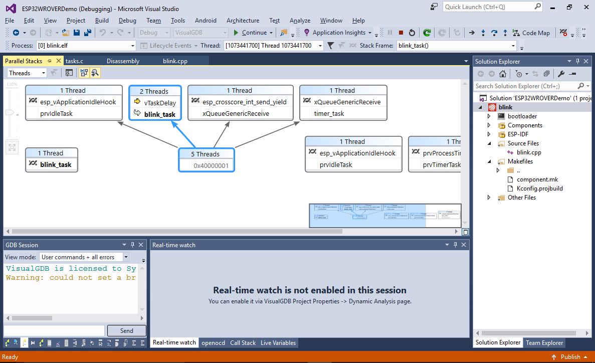
- Another option to quickly view various ESP-IDF threads would be via Debug->Parallel Stacks command. It will immediately show that 2 threads are waiting inside the vTaskDelay() function called from blink_task() while 1 thread is directly executing the blink_task():