Using Software Tracing to Record ADC Samples
This tutorial shows how to use VisualGDB’s Software Tracing feature to record the data processed by the embedded application without disrupting its workflow.
We will create a basic program that continuously samples an analog input of an STM32 chip using ADC and DMA, computes the root mean square of the deviation (corresponding to signal noisiness) and toggles an LED if the deviation exceeds the threshold. We will then use the software tracing to record all deviation values computed by the program, the exact inputs that triggered the check, and will also use it to check the state of the DMA controller at different parts of the program, to make sure the check has sufficient time to run.
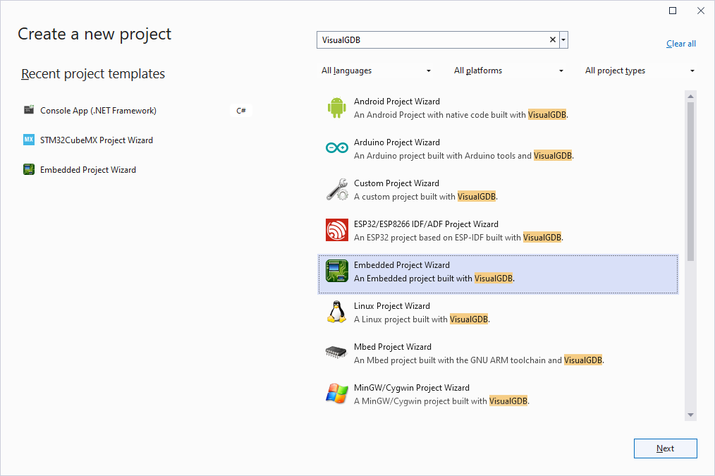
- Start Visual Studio and begin creating a new Embedded VisualGDB project:
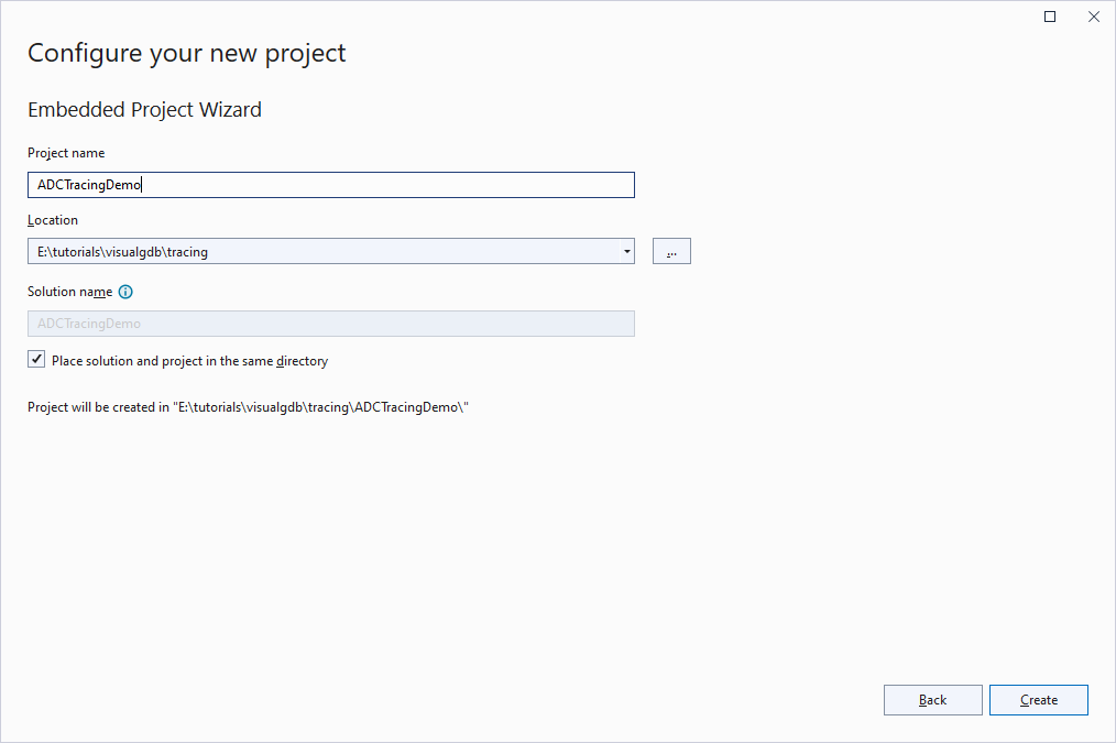
- Select the name and location of the project:
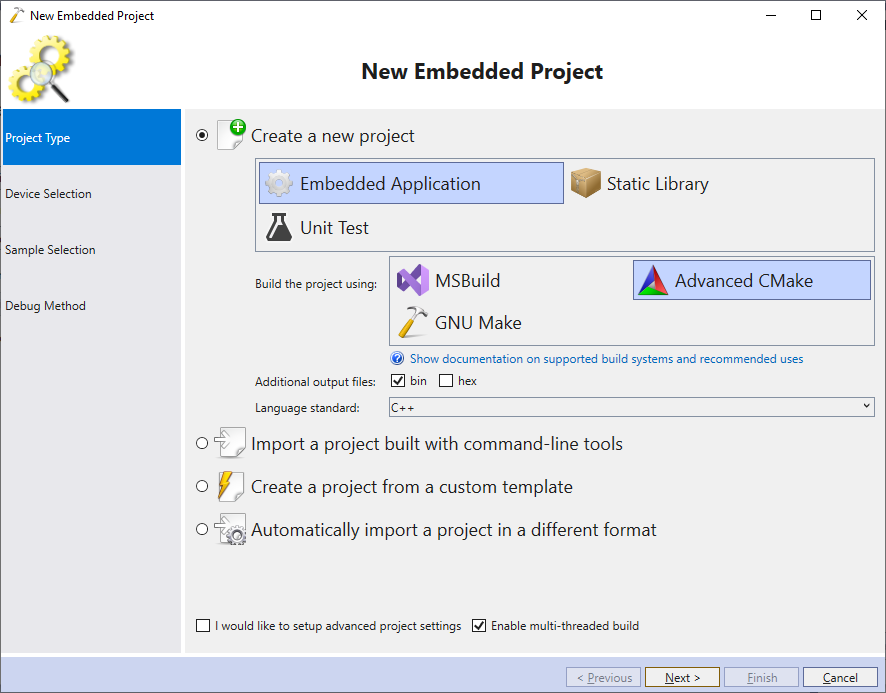
- Proceed with creating a CMake-based embedded application:
- Select the ARM toolchain and the device you would like to target:
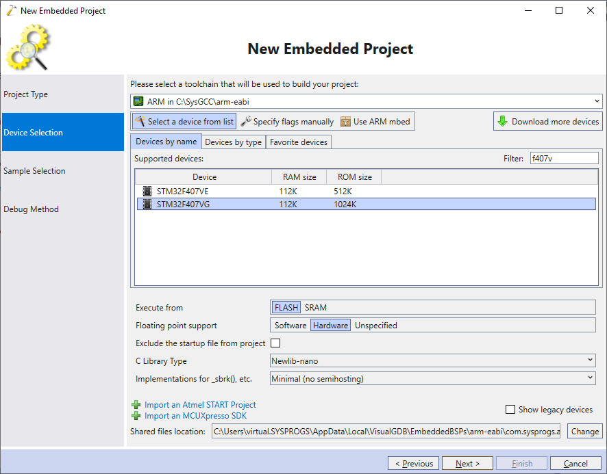
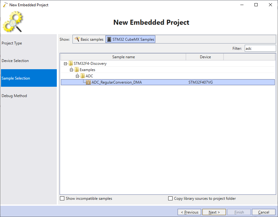
- In this tutorial we will use the STM32F4Discovery board that has numerous examples in the STM32 SDKs. Hence, pick the ADC_RegularConversion_DMA sample and click Next to proceed:
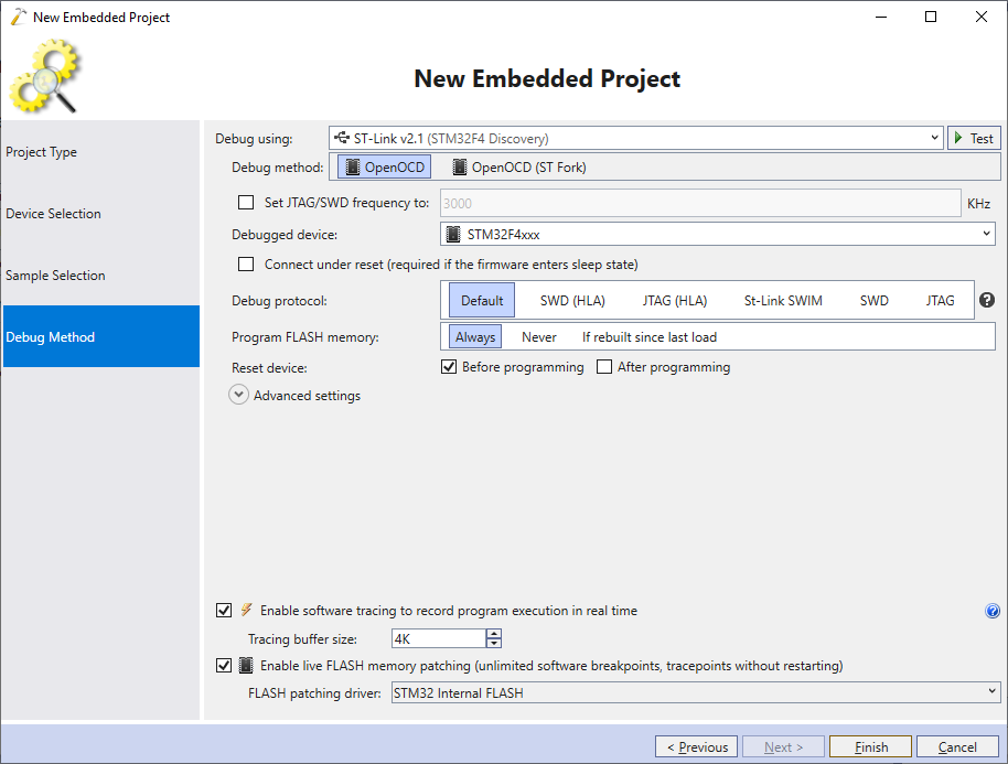
- Plug your board into the USB port and make sure VisualGDB recognizes it and fills the debug settings automatically. Then, click Finish to create the project:
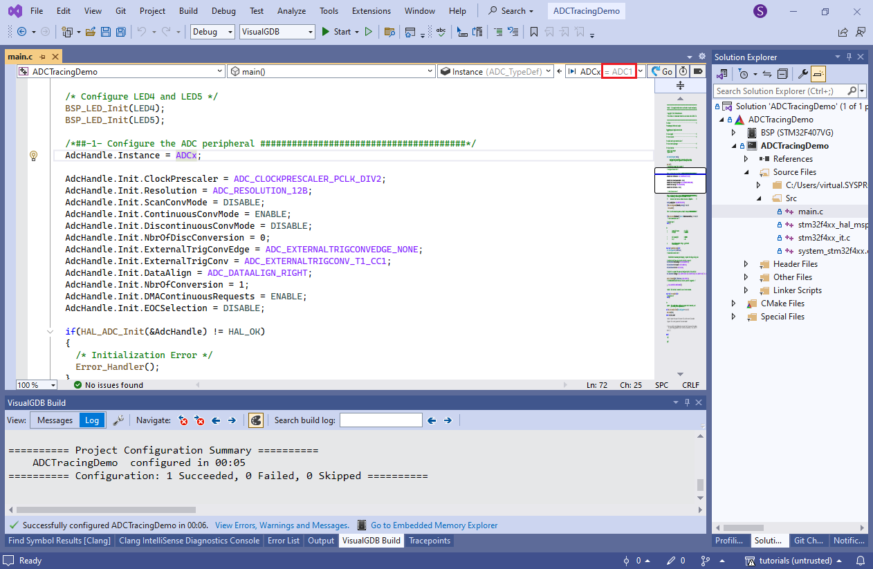
- Once the project is created, check the ADC channel used by it. The STM32 example project for STM32F4Discovery uses ADC1 channel 8:
- The example project keeps writing the captured ADC samples into the same memory location, which is not very practical. Instead, we will define a 512-sample buffer, and will configure DMA to write it in a circular fashion. Declare the following global variable:
__IO uint16_t g_ConvertedData[512];
Then, change the HAL_ADC_Start_DMA() call in main() to look like this:
if (HAL_ADC_Start_DMA(&AdcHandle,
    (uint32_t*)g_ConvertedData, sizeof(g_ConvertedData) / sizeof(g_ConvertedData[0])) != HAL_OK)
{
    Error_Handler();
}
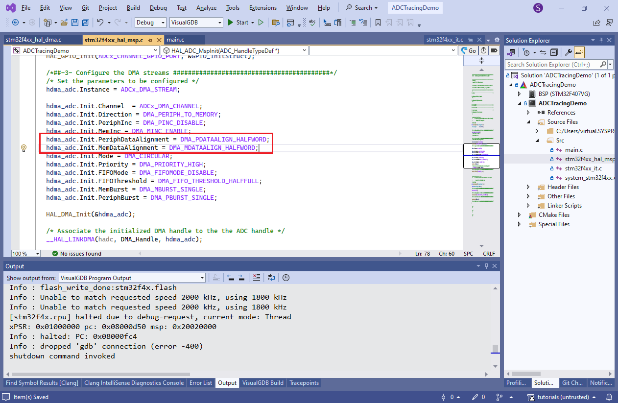
Finally, switch the peripheral and memory data alignment in stm32f4xx_hal_msp.c file to half-word, matching the 16-bit sample size:
- Now add a function that would process the captured data. Each time half of the DMA buffer gets filled, it will compute the mean value of the data in it together with the deviation, and will toggle the LED5 if the deviation exceeds a certain threshold:
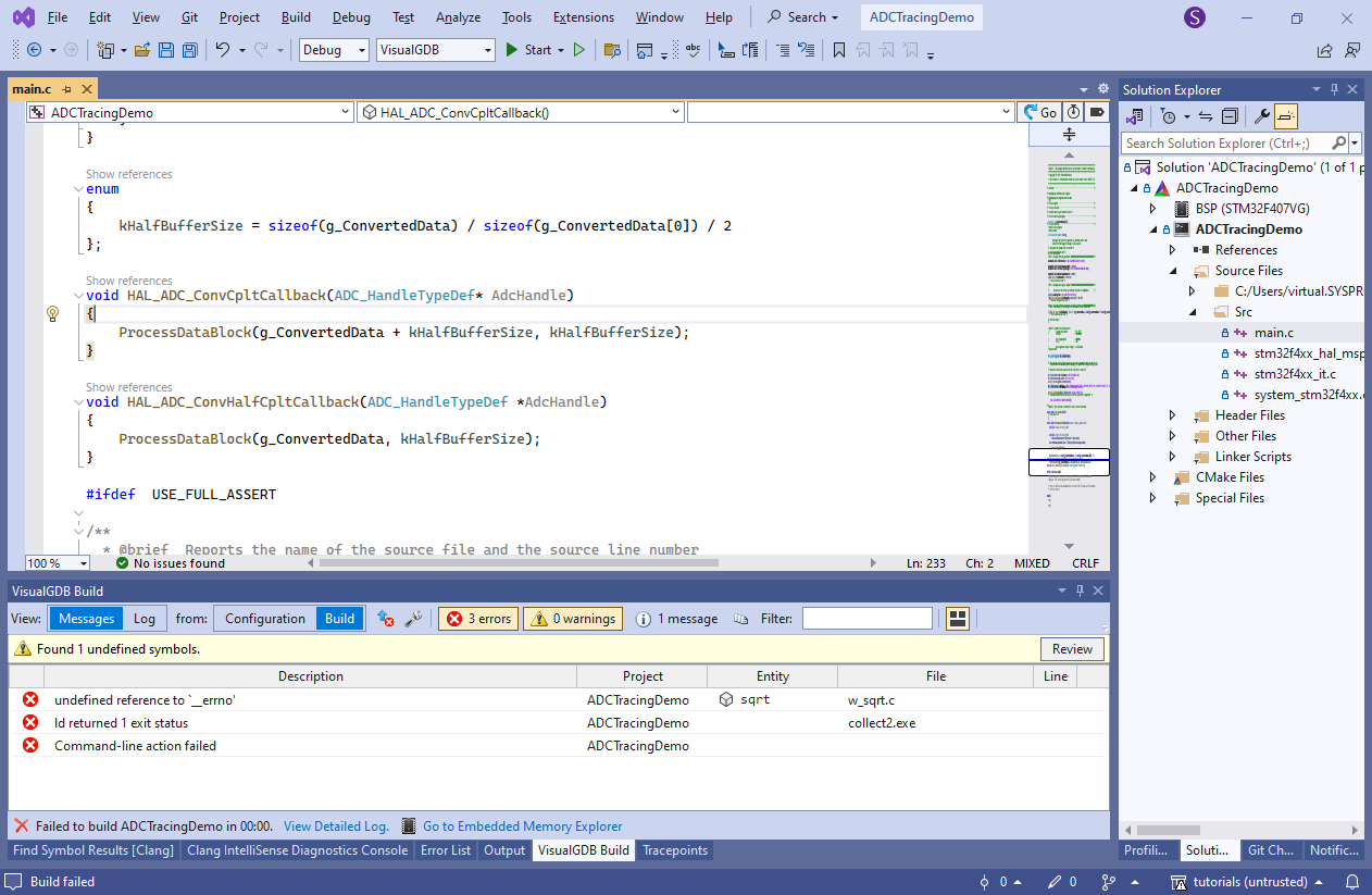
static void ProcessDataBlock(volatile uint16_t *pData, int count)
{
    int sum = 0;
    for (int i = 0; i < count; i++)
        sum += pData[i];
    int mean = sum / count;
    int deviationSquareSum = 0;

    for (int i = 0; i < count; i++)
    {
        int deviation = pData[i] - mean;
        deviationSquareSum += (deviation * deviation);
    }

    int rootMeanSquareDeviation = (int)sqrt(deviationSquareSum);
    if (rootMeanSquareDeviation > 150)
    {
        BSP_LED_Toggle(LED5);
    }
}

enum {
    kHalfBufferSize = sizeof(g_ConvertedData) / sizeof(g_ConvertedData[0]) / 2
};

void HAL_ADC_ConvCpltCallback(ADC_HandleTypeDef* AdcHandle)
{
    ProcessDataBlock(g_ConvertedData + kHalfBufferSize, kHalfBufferSize);
}

void HAL_ADC_ConvHalfCpltCallback(ADC_HandleTypeDef *AdcHandle)
{
    ProcessDataBlock(g_ConvertedData, kHalfBufferSize);
}
- Depending on your toolchain version, you may get an error about missing __errno. If this happens, simply declare it as a global variable (int __errno):
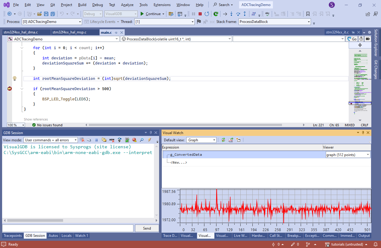
- Press F5 to start debugging and set a breakpoint in ProcessDataBlock(). You can set a regular breakpoint in ProcessDataBlock() and even visualize the contents of the buffer, however once the breakpoint triggers, the device will stop processing further data until it is resumed:
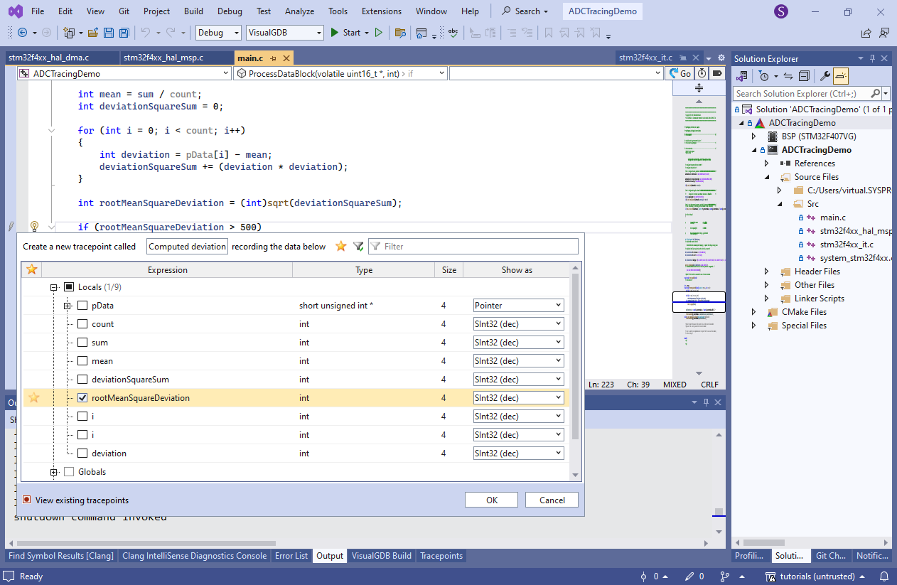
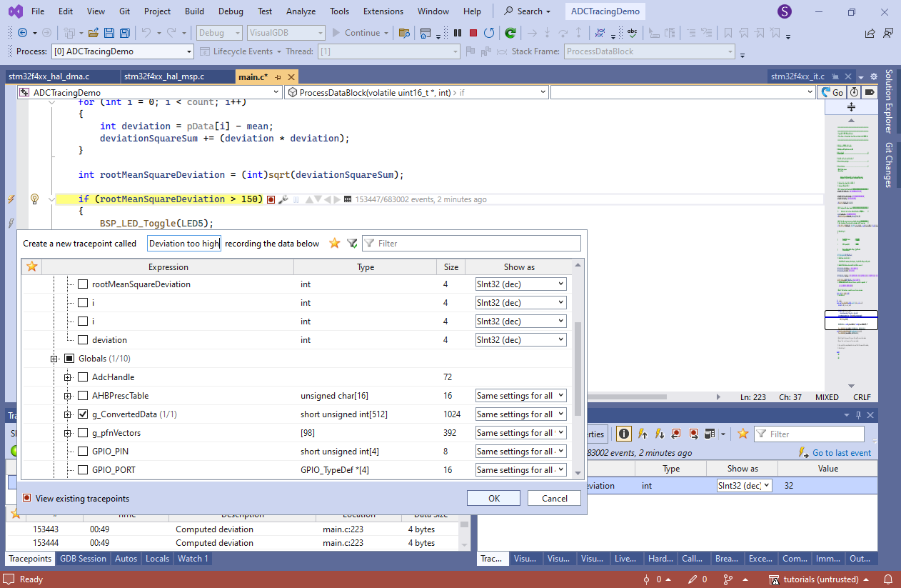
- Software Tracing is designed to avoid exactly that. Instead of stopping at a breakpoint, it quickly captures the selected data in an internal buffer and continues running. Create a tracepoint in the line that checks rootMeanSquareDeviation. Call it “computed deviation” and enable tracing of the computed value:
- Start debugging. The program will start running and the tracepoint will be generating events in real time, as long as the JTAG connection is fast enough to read them out from the RAM:
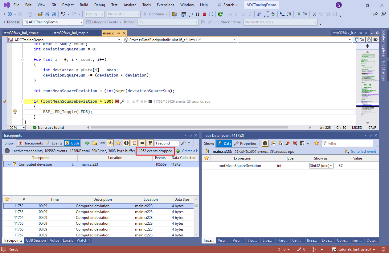
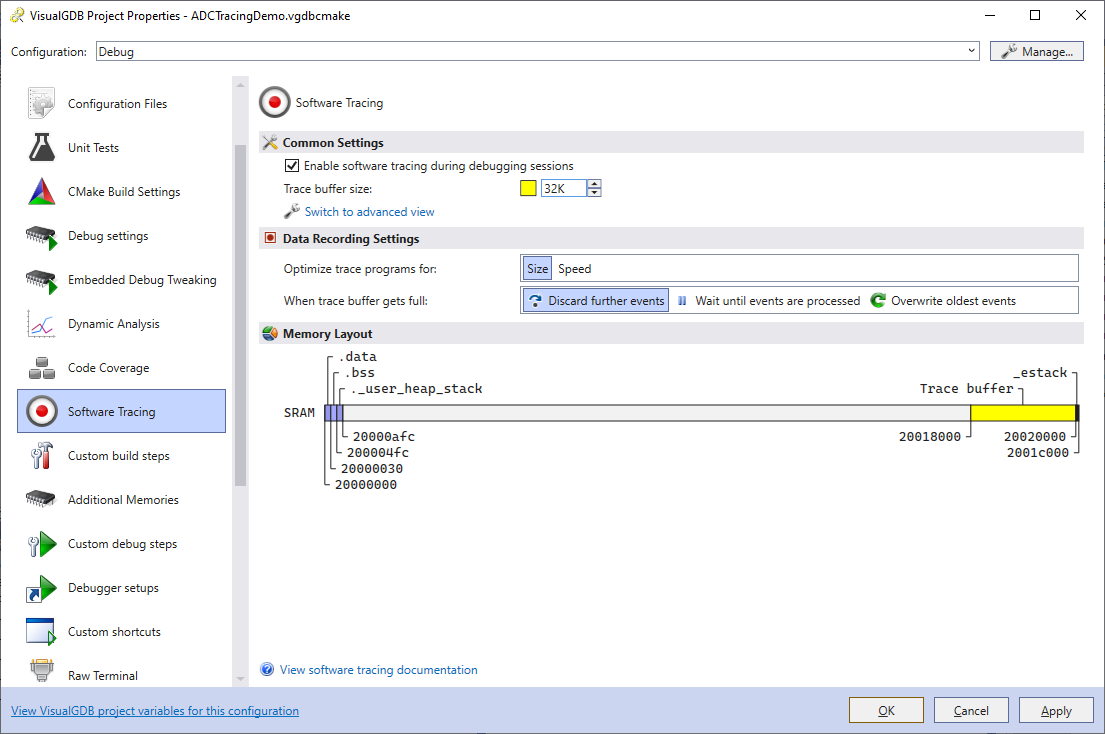
- If you experience too many dropped events, try increasing the trace buffer size via VisualGDB Project Properties -> Software Tracing:
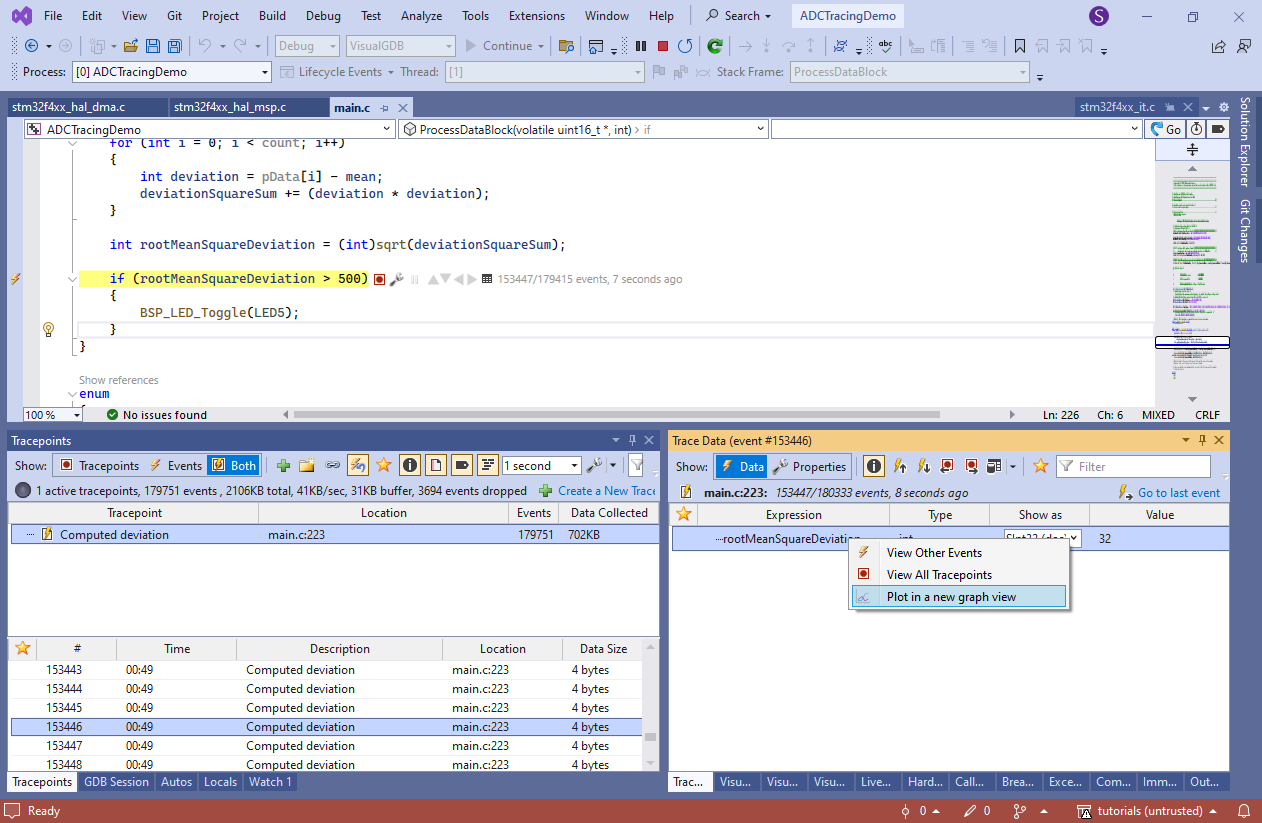
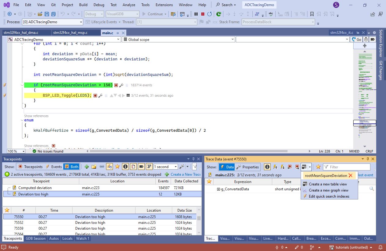
- Open the Debug->Windows->Tracepoints window while the program is running. You will see the list of all events, along with the data captured by them. Select any of the events, locate the rootMeanSquareDeviation in the Trace Data window, right-click on it and select “Plot in a new graph view”:
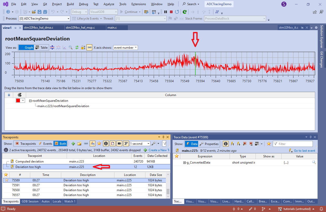
- VisualGDB will show the graph of all computed deviation values:
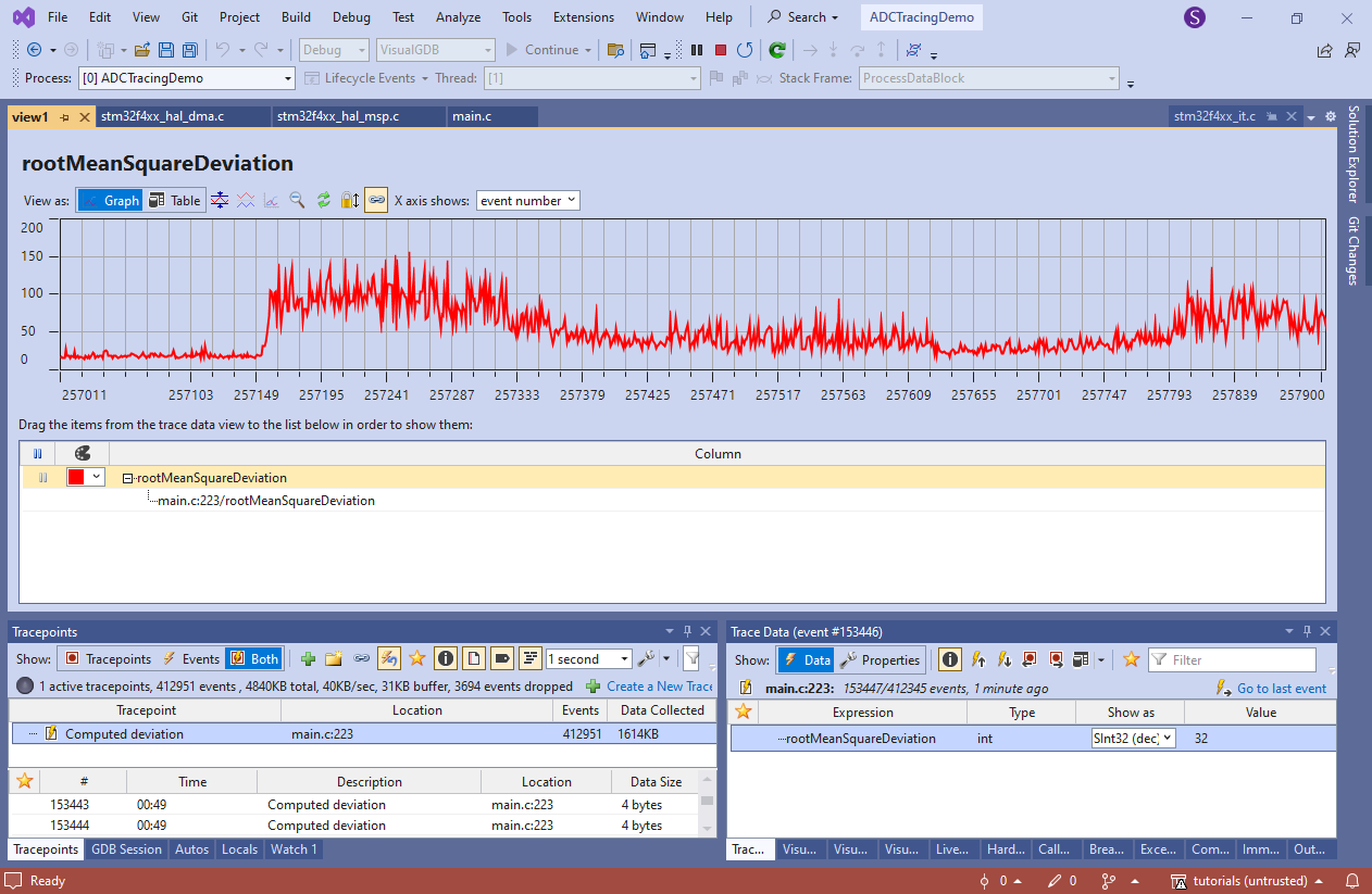 If the trace buffer was large enough to not drop any events, the graph will show every single value ever processed by the firmware.
 - Add another tracepoint on the line that toggles the LED and configure it to trace the entire g_ConvertedData:
- Connect the ADC to a noisy signal (in this tutorial we will just quickly rotate a potentiometer) and let the tracepoint generate some events. Then, go back to the graph view showing deviation values:
- Select the “deviation too high” tracepoint in the tracepoint view and pick any events there. It will highlight the nearest deviation value (captured from another tracepoint) on the graph:
 You can also navigate it the other way. Double-click on any point in the graph to see the nearby “Deviation too high” events in the event list.
 - You can use the Trace Data view to see the exact values in the g_ConvertedData buffer that lead to the excessive deviation. You can also view them in the Memory view via the “details” button, or dump to a file from there:
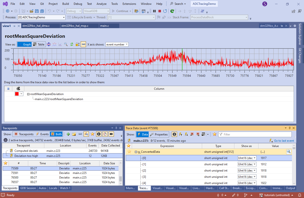
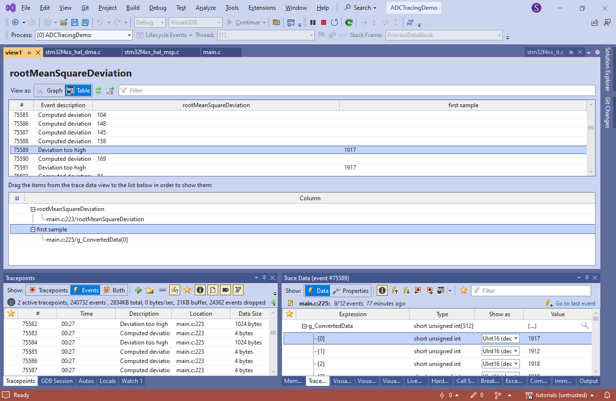
- Switch the graph view into a table and drag g_ConvertedData->[0] to the bottom area. VisualGDB will now show events from both tracepoints in the table. See how deviation values of 104, 148 and 145 don’t trigger the “too high” event, and values of 158 and 169 do (recording the exact input data):
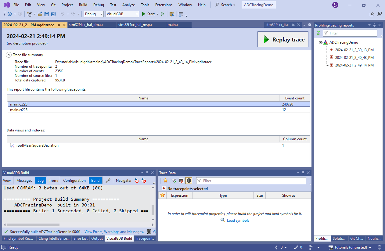
- Once you finish the debug session, VisualGDB will save all traced data in a trace report that can be replayed later at any time:
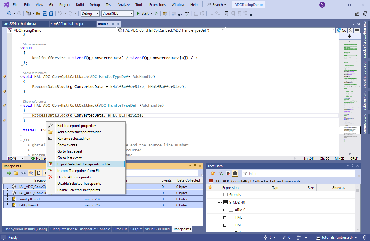
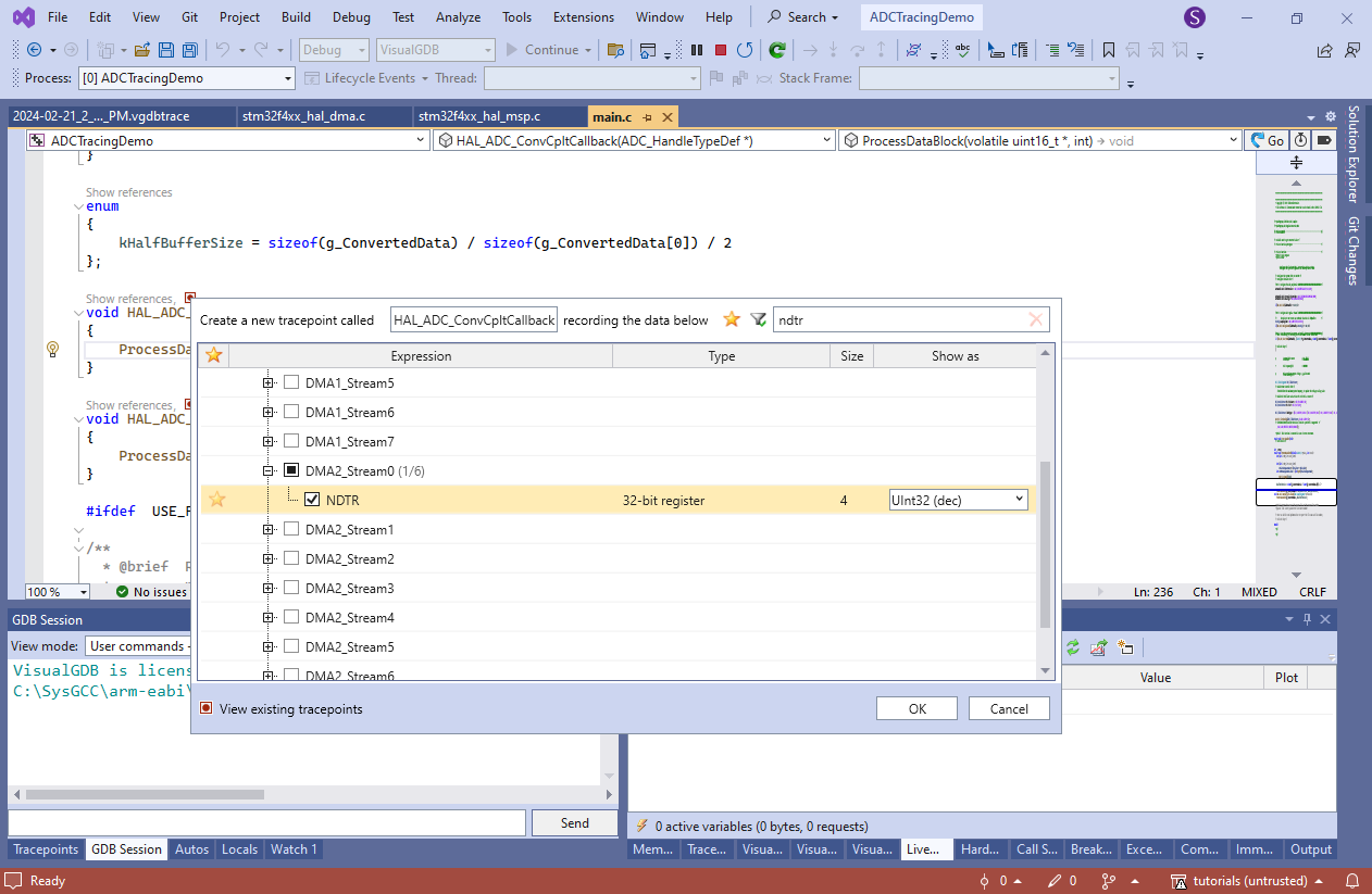
- Finally, we will show how to use software tracing to verify that the software can process the data faster than the DMA produces it. Create tracepoints at the beginning and end of HAL_ADC_ConvCpltCallback() and HAL_ADC_ConvHalfCpltCallback(), capturing the value of DMA2_Stream0->NDTR:
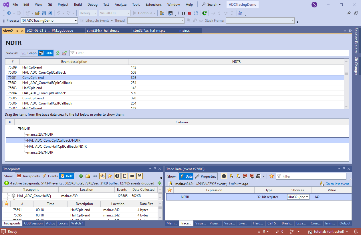
- Once the tracepoints generate enough events, create a new table view:

- Drag the NDTR values from all 4 tracepoints into the bottom area of the view. Normally, the completion event would get triggered when NDTR is reset to 512 after reaching 0, and the half-completion event would correspond to NDTR being at 256. The trace shows that it takes 3 ADC cycles for HAL_ADC_ConvCpltCallback() to get called by the interrupt handler and 111 cycles to process the data, leaving 145 cycles until the next half-completion interrupt:
- Once you finished the measurements, you can save the tracepoint configuration into an XML file, and reload it later when you want to do the same measurements again: