Using the LCD screen on the Sipeed MAIX board
This tutorial shows how to use the Kendryte K210 RTOS SDK to display text and images on the LCD display that comes with the Sipeed MAIX Dock suit.
Before you begin, follow our basic K210 tutorial to setup the JTAG wiring and verify that you can build and debug a basic project.
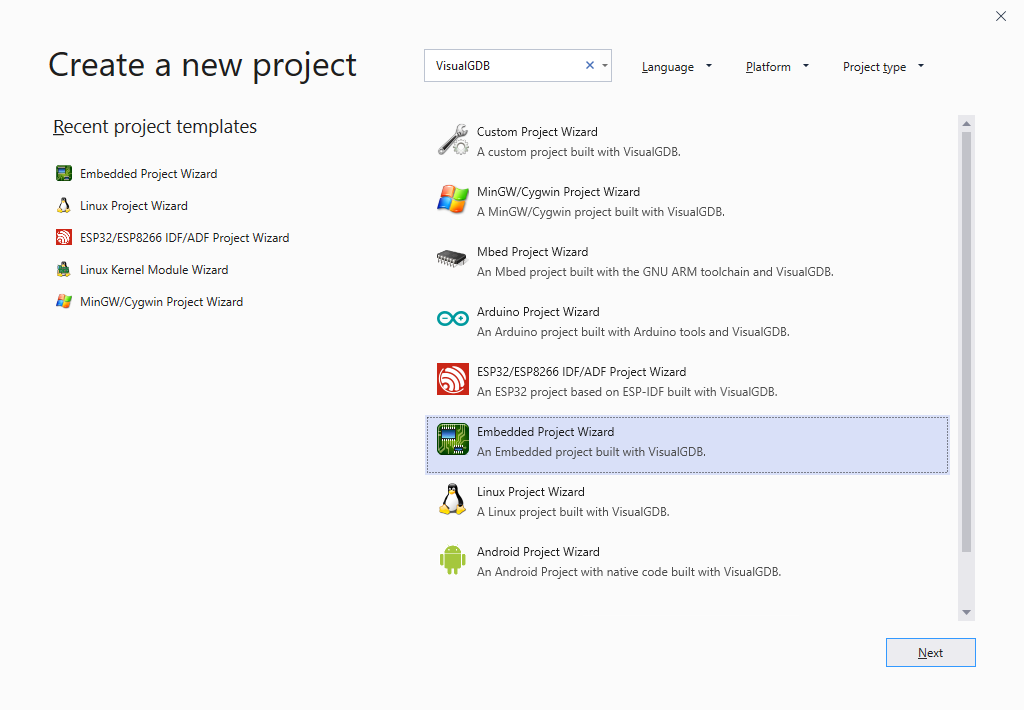
- Start Visual Studio and launch the VisualGDB Embedded Project Wizard:
- Enter the name and location for your project:

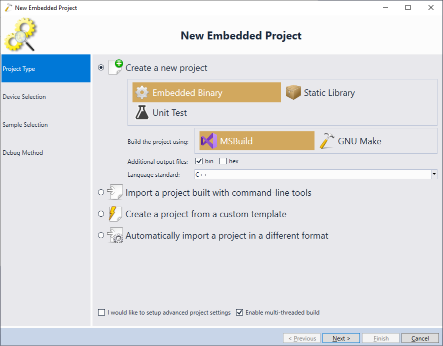
- Press “Create” go launch the VisualGDB-specific part of the wizard. On the “Project Type” page select “Create a new project -> Embedded binary -> MSBuild”:
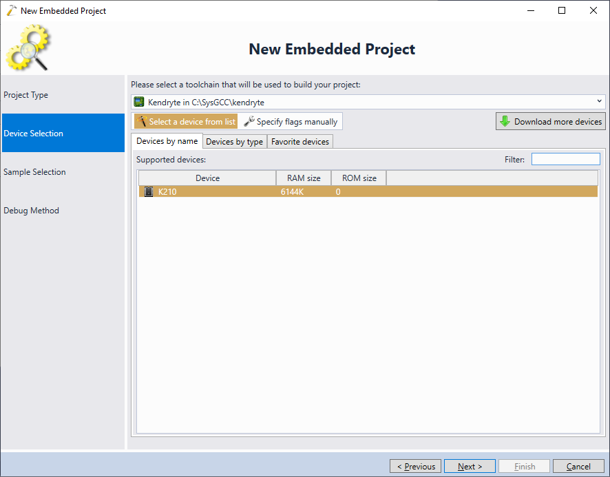
- On the next page select the K210 device:
- On the sample selection page choose K210 SDK Samples and pick a specific LCD sample in the RTOS folder. The RTOS SDK comes with 3 different LCD samples meant for different boards. The Sipeed MAIX board corresponds to the lcd_lichee_pi sample:

- Connect your JTAG debugger to the K210 chip and plug both the MAIX board and the JTAG debugger into the USB port. VisualGDB should automatically detect the debug interface:
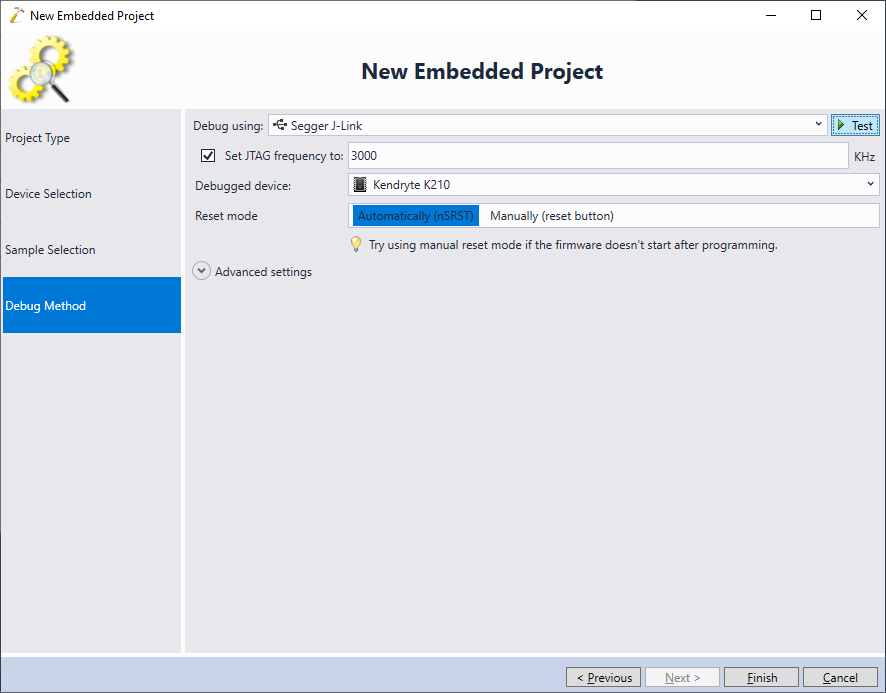 Click “Test” to verify the settings. Once the test succeeds, press “Finish” to create the project.
 - Before you can build a project with the Kendryte K210 RTOS SDK, you would need to tweak a few parameters. First of all, select all files under Source Files -> Device-specific files -> SDK (ensure you scroll all the way to the end of the SDK file list) and open Visual Studio Properties for those files. Set the optimization level for them to Medium (-O2):
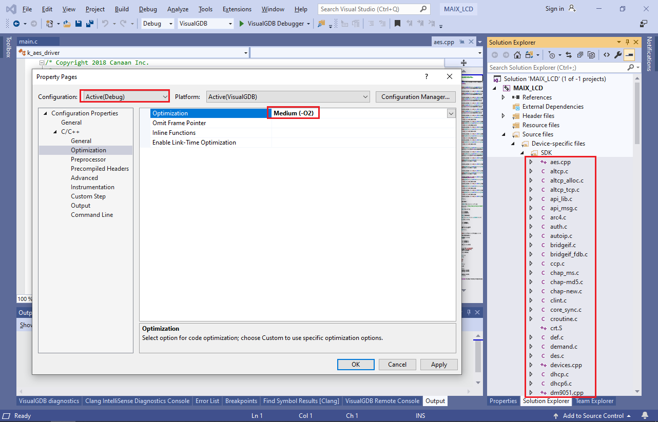 Note that this will not affect the optimization level of the rest of your project’s code, letting you debug it as usual.
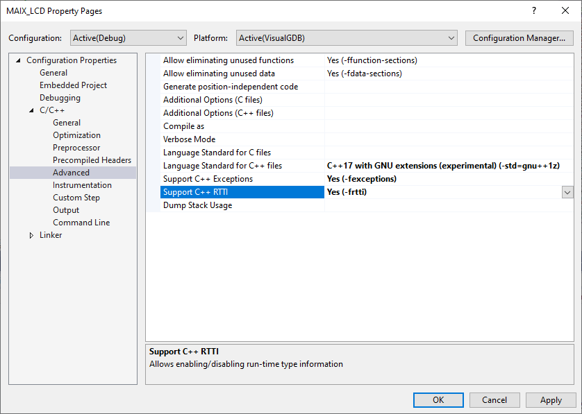
 - Open VS Project Properties for the entire project and enable C++ Exceptions and RTTI as shown below:
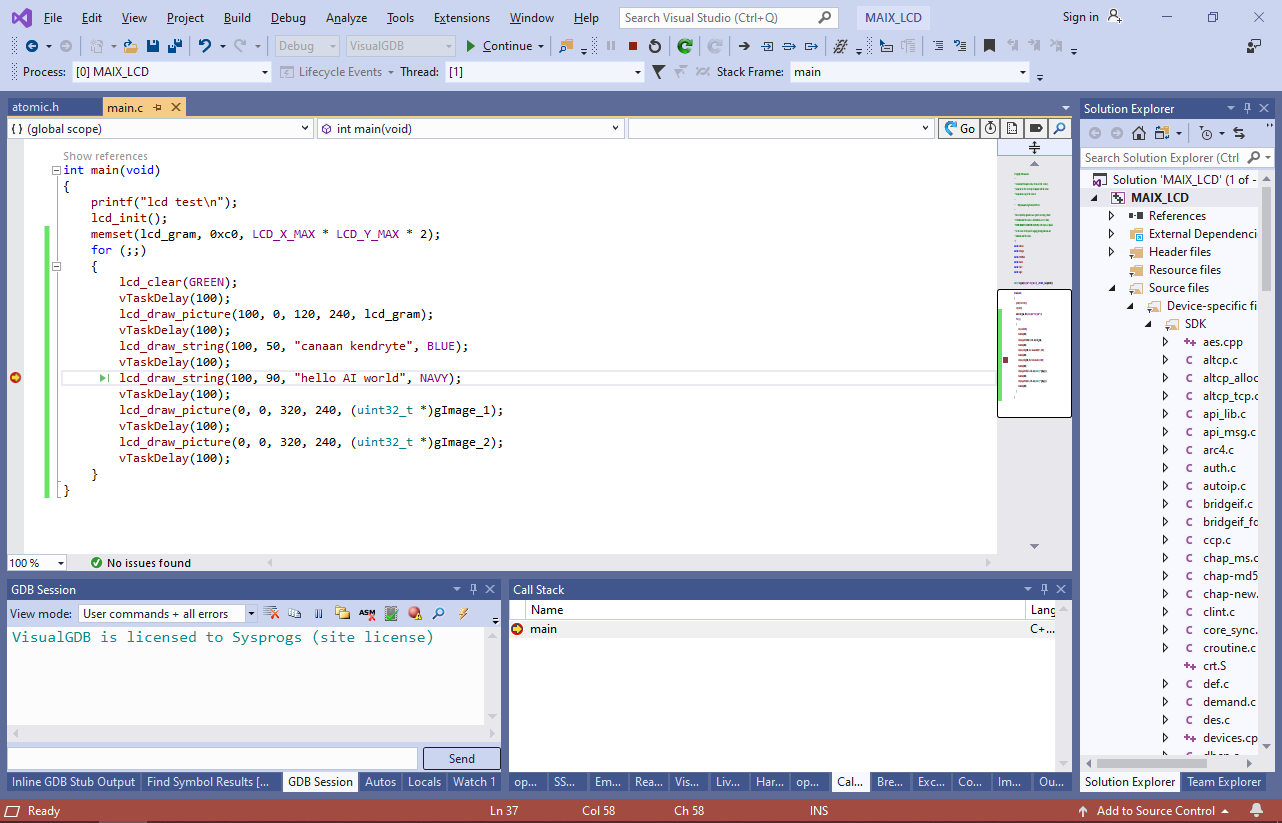
- Replace the code inside the main() function with the following:
int main(void)
{
    printf("lcd test\n");
    lcd_init();
    memset(lcd_gram, 0xc0, LCD_X_MAX * LCD_Y_MAX * 2);
    for (;;)
    {
        lcd_clear(GREEN);
        vTaskDelay(100);
        lcd_draw_picture(100, 0, 120, 240, lcd_gram);
        vTaskDelay(100);
        lcd_draw_string(100, 50, "canaan kendryte", BLUE);
        vTaskDelay(100);
        lcd_draw_string(100, 90, "hello AI world", NAVY);
        vTaskDelay(100);
        lcd_draw_picture(0, 0, 320, 240, (uint32_t *)gImage_1);
        vTaskDelay(100);
        lcd_draw_picture(0, 0, 320, 240, (uint32_t *)gImage_2);
        vTaskDelay(100);
    }
}
Then set a breakpoint inside the loop and press F5 to begin debugging the project. VisualGDB will automatically load the built project into the K210 RAM:
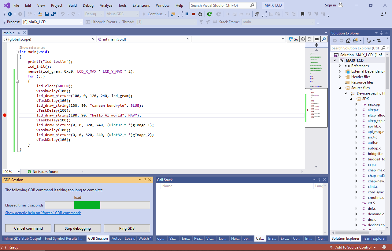
- If the project doesn’t start after being loaded, stop it via Debug->Break All and run the “load” command again via the GDB Session window:
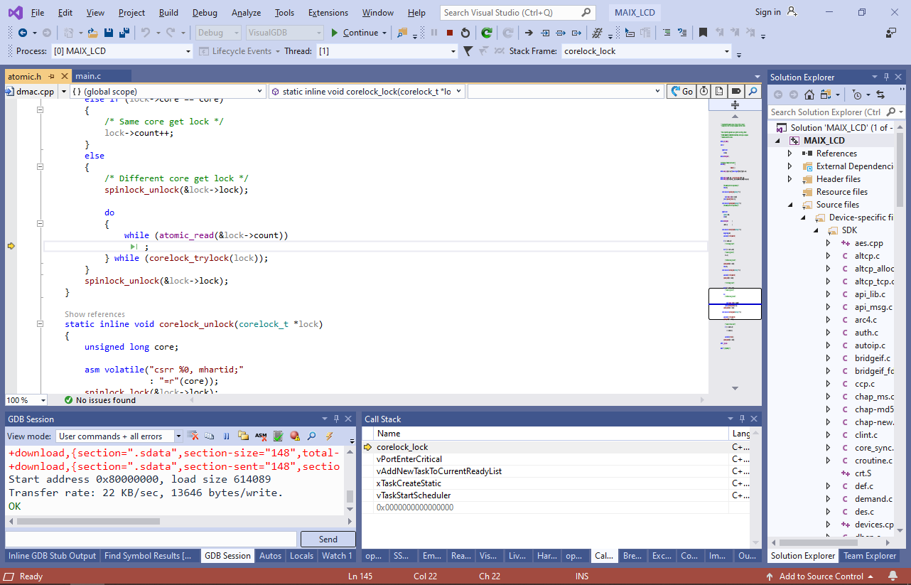
- Now you will be able to step through the code of the project:
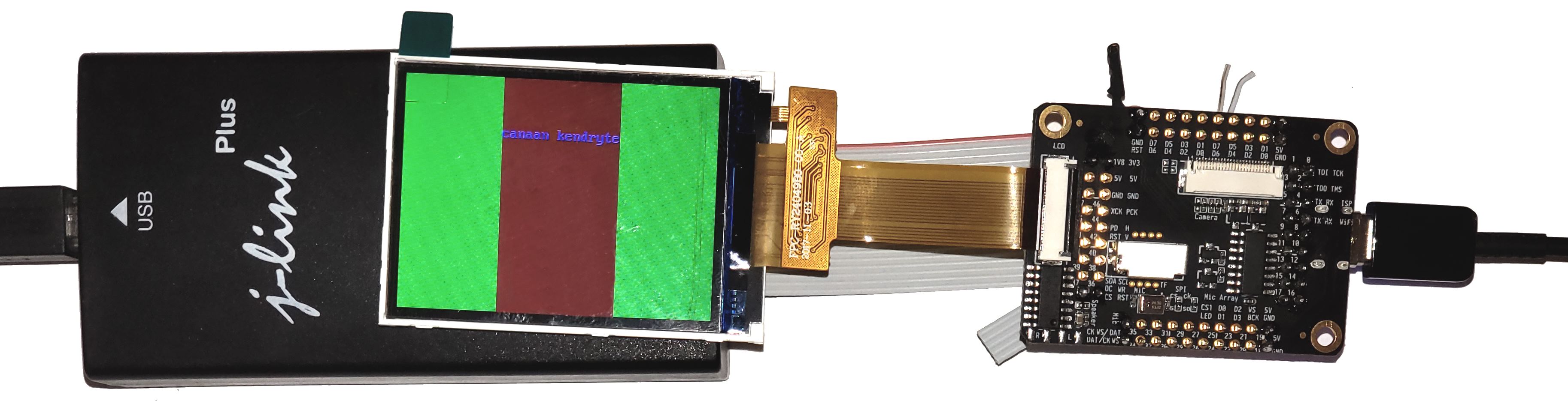
- Note how the LCD screen connected to the board gets updated each time an LCD-related function is called:
Note that the Kendryte port of OpenOCD is not as reliable as the ARM-based OpenOCD, hence debugging may not always work as expected. See our basic Kendryte K210 tutorial for tips on improving debugging reliability.