Turning Raspberry Pi Pico into an SWD Debug Probe with Picprobe
This tutorial shows how to use the Raspberry Pi Pico board as an SWD probe that can debug other targets. We will show how to setup the wiring, configure OpenOCD and build the involved firmware from scratch if you would like to modify it.
Using Raspberry Pi Pico as an SWD debuggers requires Picoprobe – the official open-source firmware implementing the SWD functionality. Picoprobe can be used together with a dedicated OpenOCD driver that has been merged into our OpenOCD fork. Picoprobe can be used to debug another Raspberry Pi, or any other target that uses the SWD interface (e.g. STM32 or NXP i.MXRT). Note that as of April 2021, JTAG-based devices, such as ESP32, could not be debugged with Picoprobe, since its firmware is missing the logic for handling JTAG signals and only works with SWD.
In order to use your Raspberry Pi Pico as an SWD probe, you need to connect the following signals to the debugged target:
| Raspberry Pi Pico signal | SWD Signal Name | Pin Number on JTAG20 Connector |
| GP2 | SWCLK | 9 |
| GP3 | SWDIO | 7 |
| GND | GND | 2, 4, 6 or 8 |
In this tutorial we will use Raspberry Pi Pico to debug the i.MXRT1050 target, but you can also use it to debug any other SWD-based device. The final wiring involving the standard JTAG20 connector is shown below: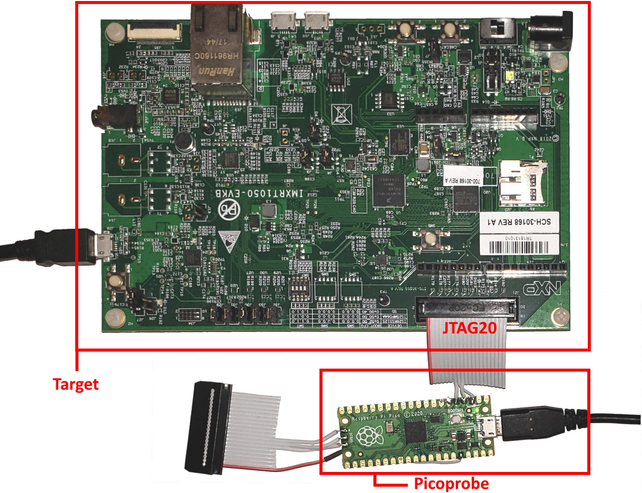
With all the wiring in place, you can follow the steps below to get the debugging working.
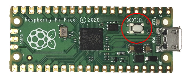
- First of all, you would need to start the Raspberry Pi Pico bootloader. Hold the BOOTSEL button and power cycle the board:
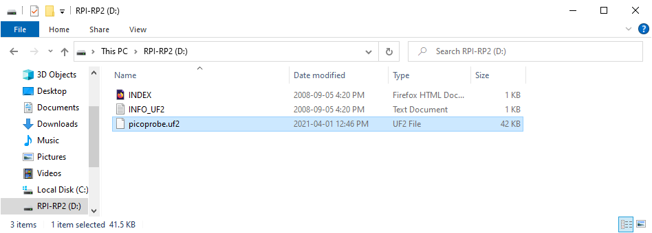
- The board will appear as a USB disk. Copy the picoprobe.uf2 file into it. You can find it inside the firmware subdirectory of our OpenOCD package. If you are using VisualGDB, it would be located under %LOCALAPPDATA%\VisualGDB\EmbeddedDebugPackages\com.sysprogs.arm.openocd:
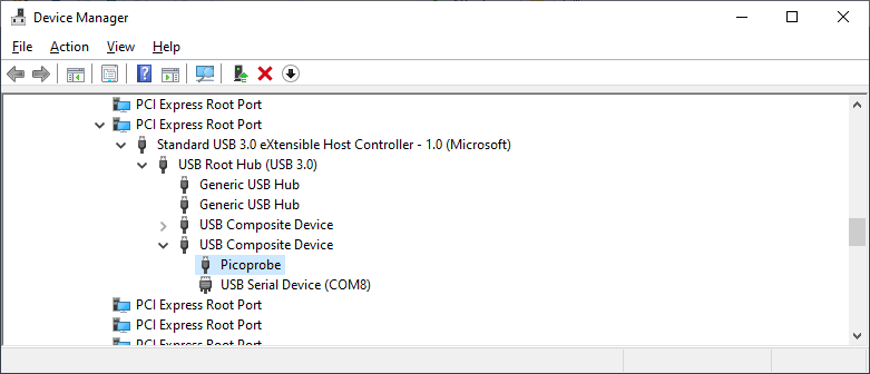
- Raspberry Pi will restart and appear in the Device Manager as a special Picoprobe device paired with a virtual COM port:
 You can use the COM port by connecting GP4 to the TX signal (data from Picoprobe to target) and GP5 to the RX signal (data from the target to Picoprobe). Make sure the target uses 0/+3.3V levels for the COM port signals: connecting Picoprobe to the ±12V levels used by RS-232 will likely damage the Picoprobe.
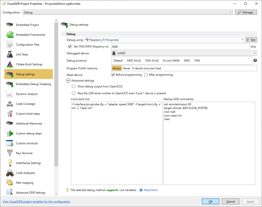
 - Now we will show how to use OpenOCD together with Picoprobe. Create a project for your target device (e.g. see this tutorial for i.MXRT-specific steps), then go to the Debug Settings. If the Picoprobe firmware is running, VisualGDB will automatically recognize it and select the interface/picoprobe.cfg script:
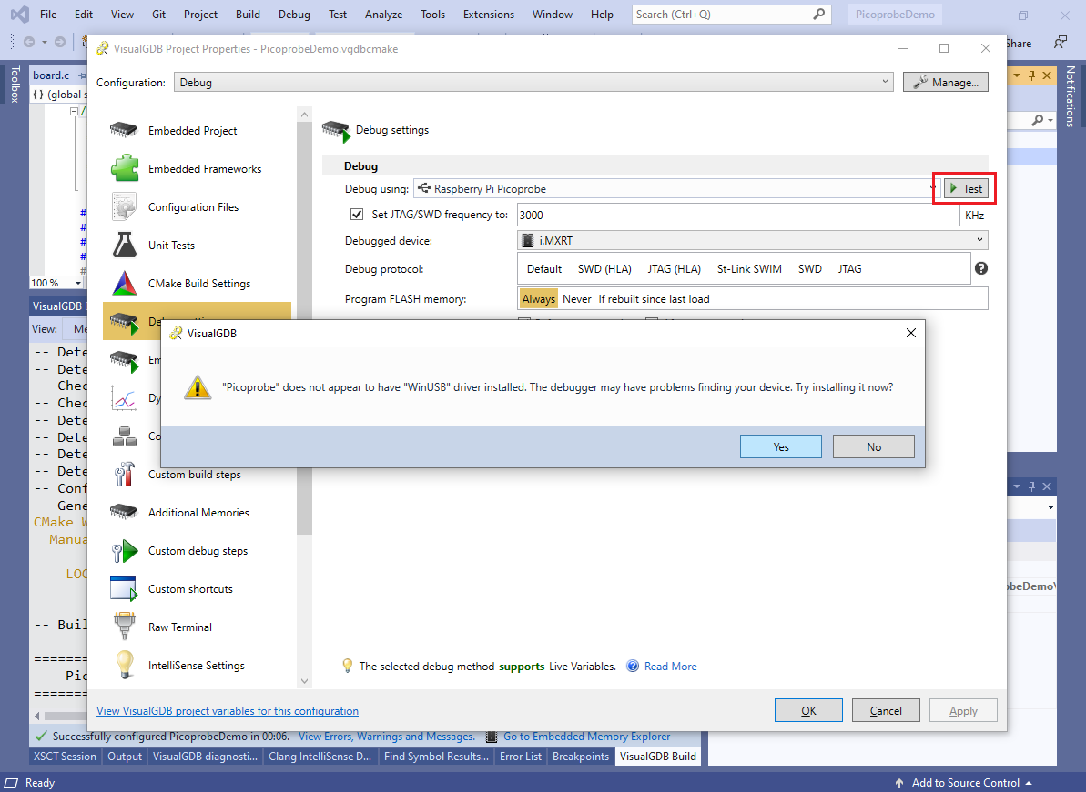
- Press the “Test” button to verify the connection. Click “yes” when VisualGDB suggests installing the WinUSB driver:
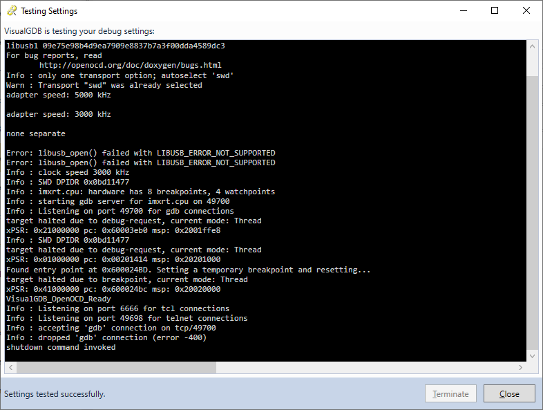
- After the driver has been installed, the connection test will succeed:
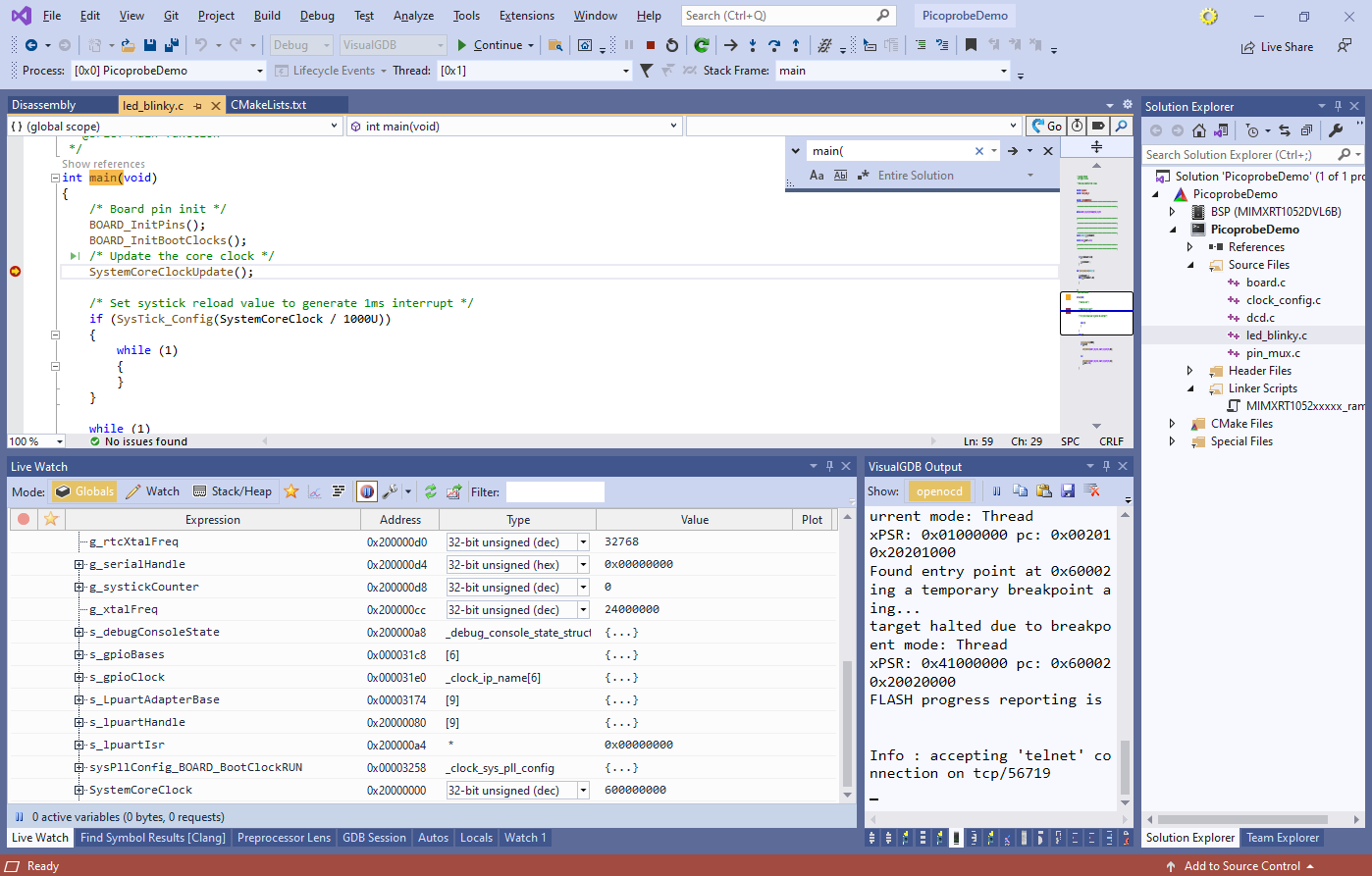
- Now you will be able to debug your target with Picoprobe. Stepping, breakpoints, expressions and Live Watch will work the same way as if you were using a different SWD probe:
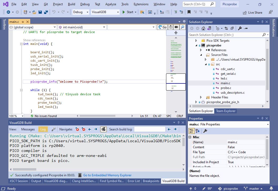
- If you would like to modify the Picoprobe firmware, you can simply clone it from the Picoprobe repository and import it into VisualGDB using the Raspberry Pi Pico Project Wizard:
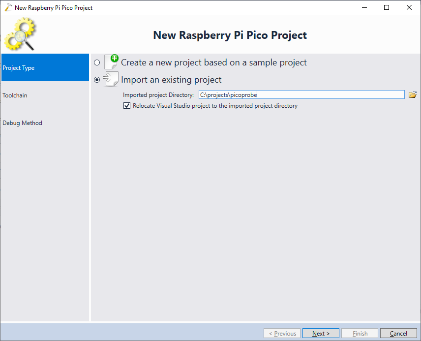
- The imported project will be built using the regular Raspberry Pi Pico SDK and will produce the .uf2 file that can be uploaded into the device: