Debugging the Sipeed Maixduino board over JTAG with VisualGDB
This tutorial shows how to create a basic Arduino-based application for the Sipeed Maixduino board and debug it with JTAG. We clone the “selfie” sample from the Maixduino platform, that takes pictures using the included camera and shows them on the LCD screen, program it into the FLASH memory using the COM port, and then show how to debug the board with JTAG.
In order to debug the board over JTAG, make sure you solder the following pins of the on-board K210 module to a JTAG20 cable (you can skip this for now, as we will first show how to build and upload the program using the on-board COM port):
| Pin Name | Pin Number | JTAG Signal | JTAG20 Pin |
| IO0/JTAG_TCK | 1 | TCK | 9 |
| IO1/JTAG_TDI | 2 | TDI | 5 |
| IO2/JTAG_TMS | 3 | TMS | 7 |
| IO3/JTAG_TDO | 4 | TDO | 13 |
| RST | 55 | SRST | 15 |
| 3V3 | (see power header on the board) | VDD | 1 |
| GND | (see power header on the board) | GND | 4 |
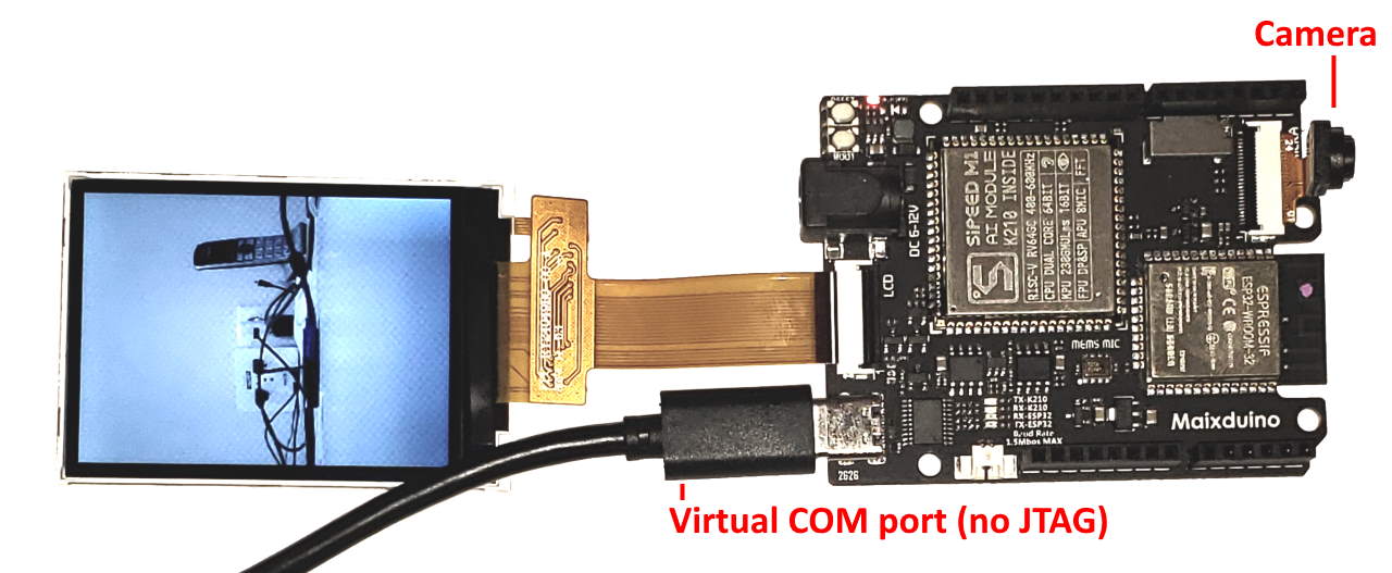
Use the schematic below to double-check the wiring: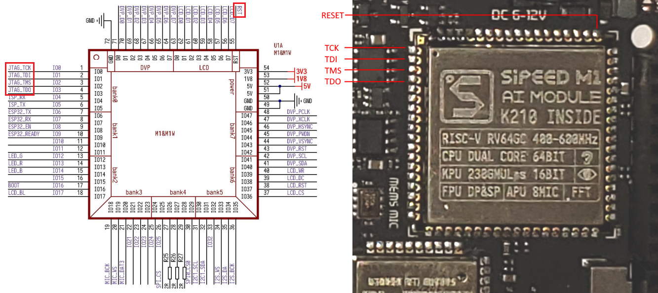 The final JTAG setup should look as shown below:
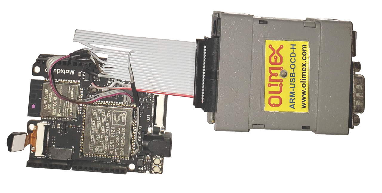 Now we will show how to create an Arduino-based VisualGDB project for Maixduino and upload it to the board. If you do not want to debug the board, you can skip the JTAG wiring setup and simply use the on-board COM port to upload the program to the FLASH memory.
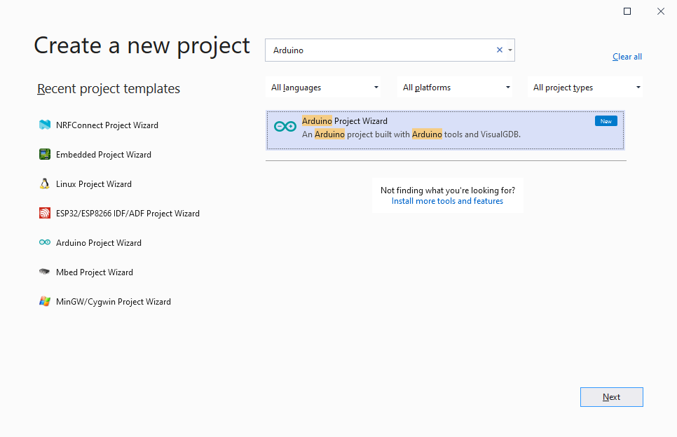
- Start Visual Studio and open the VisualGDB’s Arduino Project Wizard:
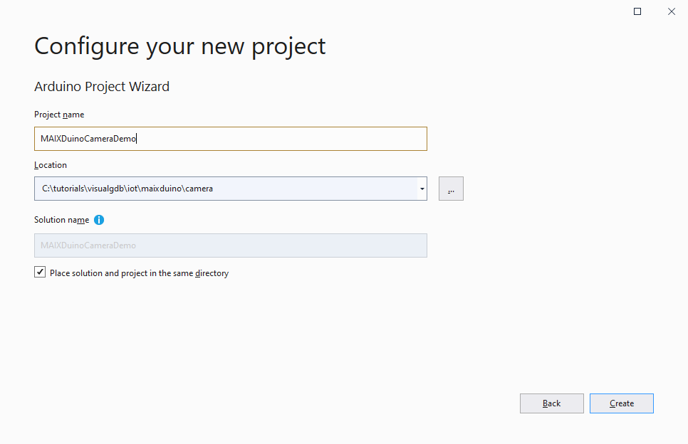
- Enter the name and location for your project:
- On the first page of the wizard select “Clone one of the sample sketches”:

- On the next page of the wizard select the Sipeed Maixduino Board. If it does not appear, make sure you are using VisualGDB 5.5 or later and the Maixduino checkbox below the target list is checked:
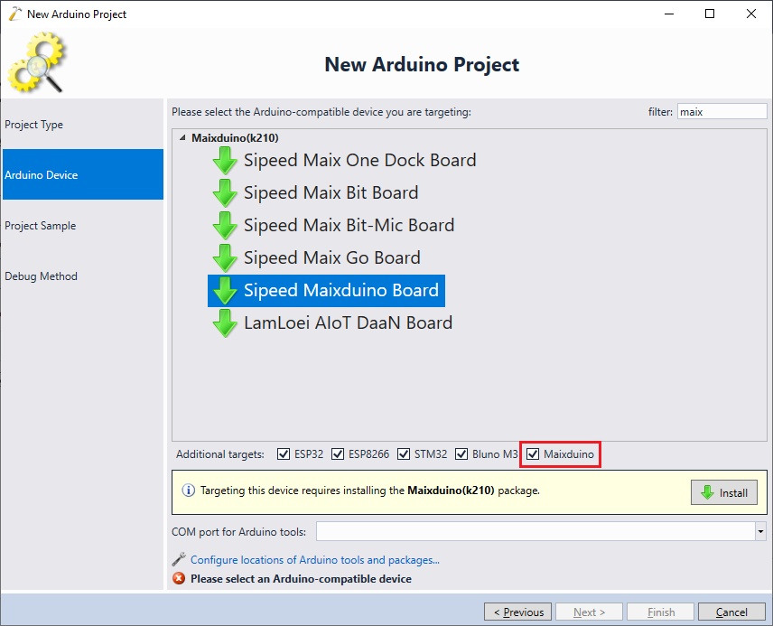
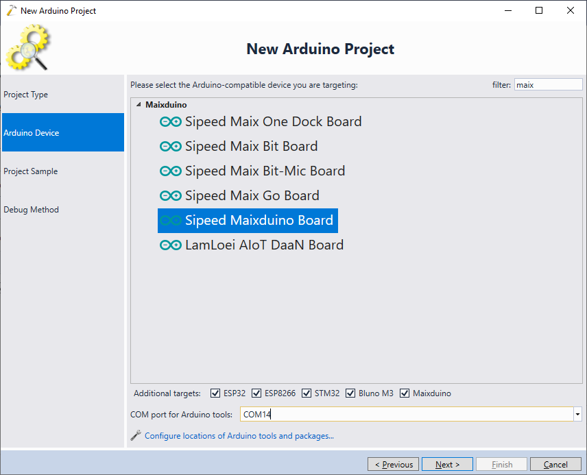
- If this is the first time you create a project for Maixduino, click “Install” to automatically download the necessary Arduino packages. Once all the packages are ready, you will be able to select the board and proceed to the next page. As we will first use the on-board COM port to program the FLASH memory, make sure you select the correct port before proceeding to the next page:
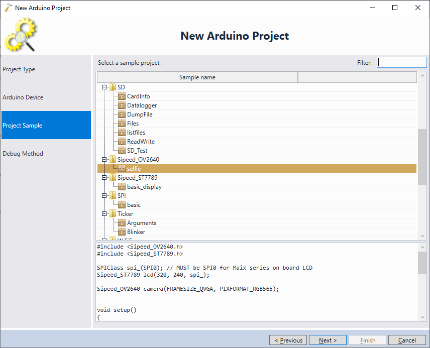
- On the Project Sample page, pick the selfie sample and click “Next”:
- Finally, you can set the debug settings for the project. If you don’t have the JTAG wiring setup yet, simply choose “built-in GDB simulator”. It won’t do any meaningful simulation for the K210 target, but will allow completing the wizard:
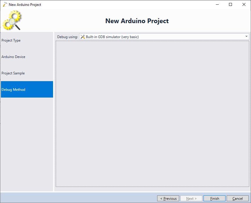 We will show the debug settings for JTAG-based debugging later in the tutorial.
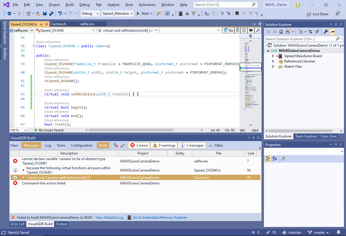
 - Press “Finish” to create the sample project, then try building it with Ctrl-Shift-B. As of June 2020, the build will fail due to a missing implementation for Camera::setRotation(uint8_t):

- You can fix the build error by navigating to definition of Sipeed_OV2640 and adding an empty implementation of setRotation() to it:
virtual void setRotation(uint8_t rotation) { }
 Note that as of June 2020, the Maixduino Arduino platform implementation does not properly generate dependency files, so changing any of the sources will rebuild the entire project.
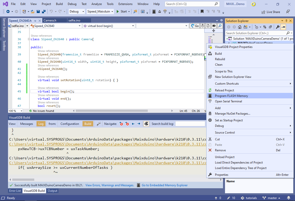
 - Once the project is built, right-click on it in Solution Explorer and select “Program FLASH memory”:
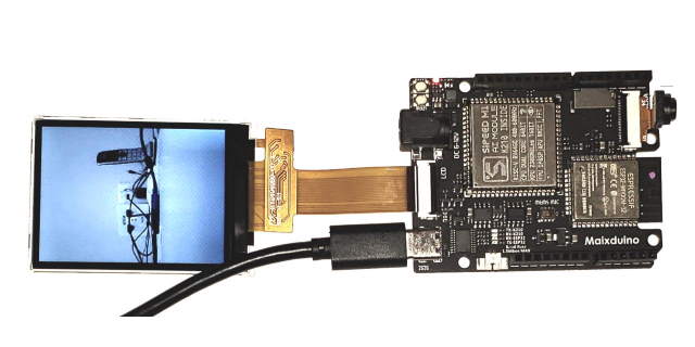
- VisualGDB will invoke the Maixduino FLASH script to automatically program the FLASH memory via the COM port. You can change the COM port number via the first page of VisualGDB Project Properties. Once the FLASH is programmed, the on-board LCD screen will show the live feed from the camera:
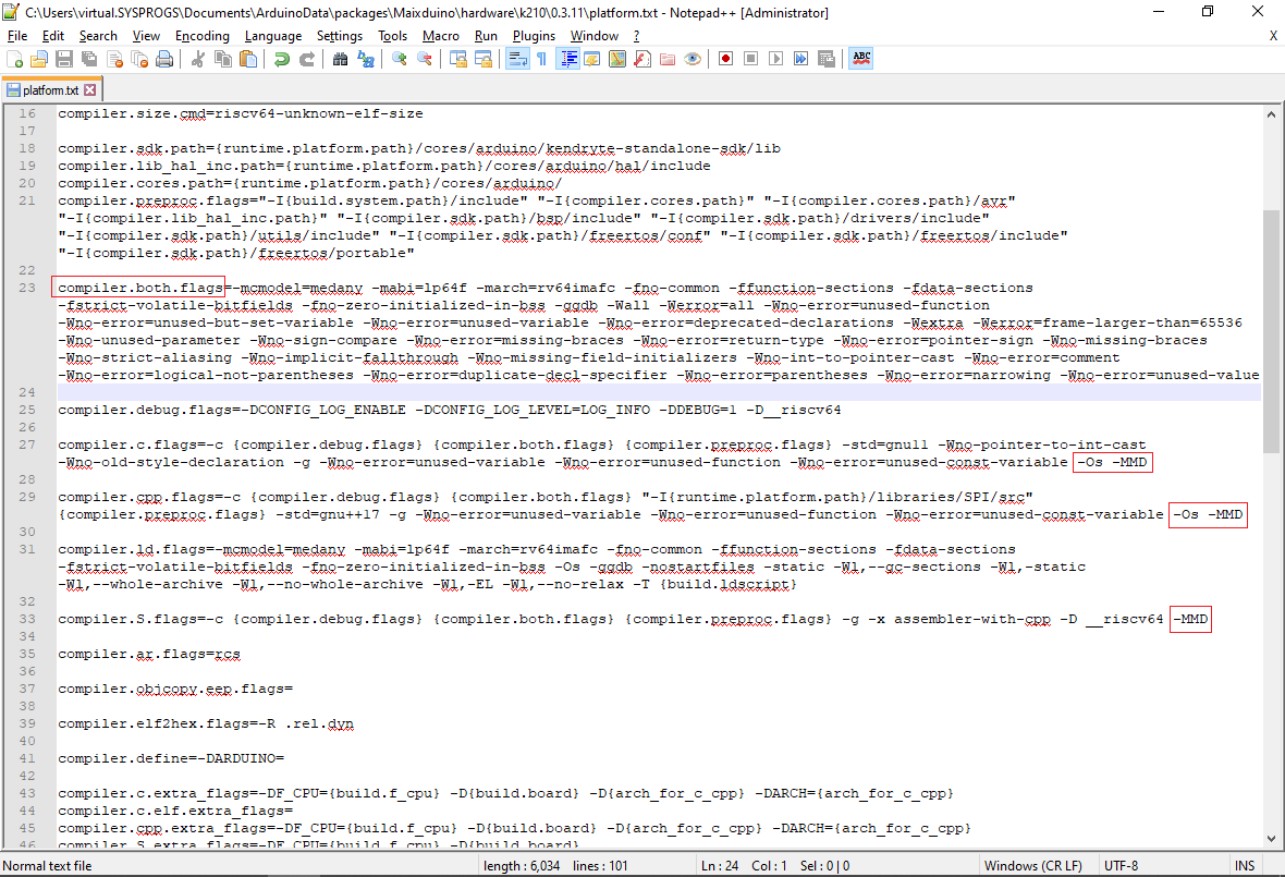
- Before you go further, we recommend patching the <Documents>\ArduinoData\packages\Maixduino\hardware\k210\0.3.11\platform.txt file as shown below (you can find out the exact path by opening any file from the Sipeed Maixduino Board folder in Solution Explorer and checking its full path in Visual Studio):
- Remove “-Os” from compiler.both.flags and add it to compiler.c.flags and compiler.cpp.flags.
- Add “-Os” to compiler.c.flags and compiler.cpp.flags.
- Add “-MMD” to compiler.c.flags, compiler.cpp.flags and compiler.S.flags
This will enable dependency file generation, greatly reducing the build time, and will allow VisualGDB to disable optimization for debug builds if enabled via VisualGDB Project Properties:
- Now we will show how to debug the Maixduino board with JTAG. Make sure you followed the JTAG wiring setup instructions from the beginning of the page, connect your JTAG debugger to the board and open VisualGDB Project Properties. Select the probe in the “Debug using” field an click “Test”:
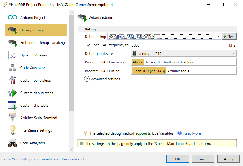 If everything is connected correctly, the test will succeed:
 We have tested the Maixduino board with both Olimex ARM-USB-OCD-H and Segger J-Link debuggers (both using OpenOCD).
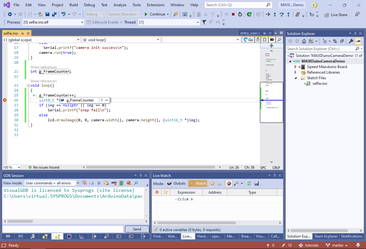
 - Try adding a simple frame counter variable to loop(), set a breakpoint there and begin debugging. VisualGDB will load the program into the Maixduino RAM and will start debugging:
 Note that the debugging experience using the K210 OpenOCD is less reliable compared to ARM (and other RISC-V) devices (see the end of this tutorial for details). Although the regular breakpoints and stepping work, we have found the following debugging limitations during our tests:
- The debug session sometimes doesn’t start properly. Restarting it a few times fixes the problem.
- Adding/removing breakpoints while the target is running often crashes the target.
- Resetting the target programmatically may not always work.
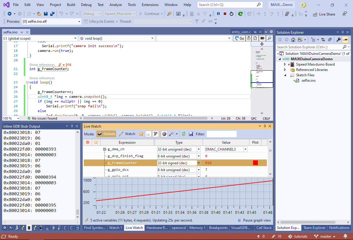
- You can also use VisualGDB’s Live Watch window to monitor the values of different variables while the target is running. This will not interfere with the debug session: